
User's Manual


Appendix B Verification and Calibration
98 Series N5700 User’s Guide
4 Program the power supply to program the output current to its
maximum programmable value (Imax) and the output voltage to
its full-scale value and enable the output. Let the oscilloscope run
for a few seconds to generate enough measurement points. On
the Agilent Infiniium scope, the maximum peak-to-peak voltage
measurement is indicated at the bottom of the screen on the right
side. Divide this value by 10 to get the CV peak-to-peak noise
measurement. The result should not exceed the peak-to-peak
limits in the test record form for the appropriate model under CV
Ripple and Noise, peak-to-peak.
(If the measurement contains any question marks, clear the
measurement and try again. This means that some of the data
received by the scope was questionable.)
5 Disconnect the oscilloscope and connect an ac rms voltmeter in
its place. Do not disconnect the 50 Ω termination. Divide the
reading of the rms voltmeter by 10. The result should not exceed
the rms limits in the test record card for the appropriate model
under CV Ripple and Noise - rms.
Transient Recovery Time
Test category = performance
This measures the time for the output voltage to recover to within the
specified value following a 10% to 90% change in the load current.
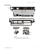
1 Turn off the power supply and connect the output as in figure A
with the oscilloscope across the +S and -S terminals.
2 Turn on the power supply and program the output current to its
maximum programmable value (Imax) and the output voltage to
its full-scale value. Do not program voltages greater than 200
VDC when testing the 300 and 600 volt models.
3 Set the electronic load to operate in constant current mode.
Program its load current to 10% of the power supply’s full-scale
current value.
4 Set the electronic load's transient generator frequency to 100 Hz
and its duty cycle to 50%.
5 Program the load's transient current level to 90% of the power
supply's full-scale current value. Turn the transient generator on.
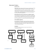
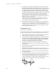
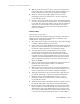
6 Adjust the oscilloscope for a waveform similar to that shown in
the following figure.
7 The output voltage should return to within the specified voltage
in the specified time following the 10% to 90% load change. Check
both loading and unloading transients by triggering on the
positive and negative slope. Record the voltage at time “t” in the
performance test record card under Transient Response.
tttt
t
v
Loading
Transient
Unloading
Transient
v
t