
User's Manual


Appendix B Verification and Calibration
96 Series N5700 User’s Guide
Constant Voltage Tests
NOTE
Refer to the appropriate test record form for the instrument settings of the
model you are checking.
Voltage Programming and Readback Accuracy
Test category = performance, calibration
This test verifies that the voltage programming and measurement
functions are within specifications.
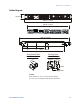
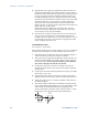
1 Turn off the power supply and connect a DVM directly across the
+S and -S terminals as shown in figure A. Do not connect a load.
2 Turn on the power supply and program the output voltage to zero
and the output current to its maximum programmable value
(Imax) with the load off. The CV annunciator should be on and
the output current reading should be approximately zero.
3 Record the output voltage readings on the digital voltmeter
(DVM) and the front panel display. The readings should be within
the limits specified in the test record card for the appropriate
model under Voltage Programming and Readback, Minimum
Voltage Vout.
4 Program the output voltage to its full-scale rating.
5 Record the output voltage readings on the DVM and the front
panel display. The readings should be within the limits specified
in the test record card for the appropriate model under Voltage
Programming and Readback, High Voltage Vout.
CV Load Effect
Test category = performance
This test measures the change in output voltage resulting from a
change in output current from full load to no load.
1 Turn off the power supply and connect a DVM and an electronic
load as shown in figure A.
2 Turn on the power supply and program the output current to its
maximum programmable value (Imax) and the output voltage to
its full-scale value.
3 Set the electronic load for the output’s full-scale current. The CV
annunciator on the front panel must be on. If it is not, adjust the
load so that the output current drops slightly.
4 Record the output voltage reading from the DVM.
5 Open the load and record the voltage reading from the DVM
again. The difference between the DVM readings in steps 4 and 5
is the load effect, which should not exceed the value listed in the
test record card for the appropriate model under CV Load Effect.