
User's Manual

1 Quick Reference
14 Series N5700 User’s Guide
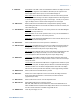
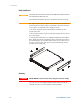
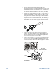
J1 Analog Programming Connector
The factory-shipped default configuration is Local operation, which
does not require connection to J1.
Pin 1: Enable + Connect Pin 1 to Pin 14 to enable the output. Disconnect to disable the output.
Pin 2, 3: Chassis Common Signal return for Pin 15 and Pin 16. Connected to chassis.
Pin 4–7: Not Used No connection
Pin 8: Local/Analog Input for selecting between front panel or analog programming of the output.
Pin 9: Voltage Program Input for voltage or resistance programming of the output voltage.
Pin 10: Current Program Input for voltage or resistance programming of the output current.
Pin 11: Voltage Monitor Output for monitoring the output voltage.
Pin 12: Common Signal return for Pin 8, Pin11, Pin 13, and Pin 24. Connected internally to –S.
Pin 13: CV/CC Output for constant voltage/constant current mode indication.
Pin 14: Enable – Connect Pin 14 to Pin 1 to enable the output. Disconnect to disable the output.
Pin 15: Shut Off Input for Shut-Off control of the output. Referenced to Chassis Common.
Pin 16: Power Supply OK Output to indicate the power supply status. Referenced to Chassis Common.
Pin 17–20: Not Used No connection
Pin 21: Local/Analog State Output for indication of local or analog programming mode.
Pin 22: Voltage Prog. Return Signal return for Pin 9. Connected internally to –S.
Pin 23: Current Prog. Return Signal return for Pin 10. Connected internally to –S.
Pin 24: Current Monitor Output for monitoring the output current.
Pin 25: Parallel Output for current balancing in parallel operation.
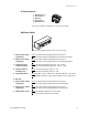
14151617
18
19
20
21
22
232425
12
3
45
6
7
8
10
11
12
13
9
Current Monitor
Current Prog. Return
Voltage Prog. Return
Local / Analog State
Chassis Common
Enable +
Voltage Monitor
Common (-S)
CV / CC
Current Program
Voltage Program
Local / Analog
Parallel Enable --
Shut Off
Power Supply OK
Chassis Common