Service Guide Publication Number 33120-90017 (order as 33120-90104 manual set) Edition 6, March 2002 © Copyright Agilent Technologies, Inc. 1994-2002 For Safety information, Warranties, and Regulatory information, see the last page in this manual.
Note: Unless otherwise indicated, this manual applies to all Serial Numbers. The Agilent Technologies 33120A is a high-performance 15 MHz synthesized function generator with built-in arbitrary waveform capability. Its combination of bench-top and system features makes this function generator a versatile solution for your testing requirements now and in the future.
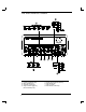
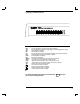
The Front Panel at a Glance 1 2 3 4 2 Function / Modulation keys Menu operation keys Waveform modify keys Single / Internal Trigger key (Burst and Sweep only) 5 6 7 8 Recall / Store instrument state key Enter Number key Shift / Local key Enter Number “units” keys
Front-Panel Number Entry You can enter numbers from the front-panel using one of three methods. Use the knob and the arrow keys to modify the displayed number. Use the arrow keys to edit individual digits. Increments the flashing digit. Decrements the flashing digit. Moves the flashing digit to the right. Moves the flashing digit to the left. Use the “Enter Number” mode to enter a number with the appropriate units.
The Front-Panel Menu at a Glance The menu is organized in a top-down tree structure with three levels.
Display Annunciators Adrs Rmt Trig AM FM Ext FSK Burst Swp ERROR Offset Shift Num Arb Function generator is addressed to listen or talk over a remote interface. Function generator is in remote mode (remote interface). Function generator is waiting for a single trigger or external trigger (Burst, Sweep). AM modulation is enabled. FM modulation is enabled. Function generator is set for an external modulation source (AM, FSK, Burst). FSK (frequency-shift keying) modulation is enabled.
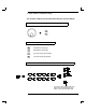
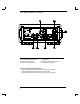
The Rear Panel at a Glance 1 2 3 4 Chassis ground Power-line fuse-holder assembly Power-line voltage setting AM modulation input terminal 5 External Trigger / FSK / Burst modulation input terminal 6 GPIB (IEEE-488) interface connector 7 RS-232 interface connector Use the front-panel Input / Output Menu to: Select the GPIB or RS-232 interface (see chapter 4 in User’s Guide). Set the GPIB bus address (see chapter 4 in User’s Guide).
In This Book Specifications Chapter 1 lists the function generator’s specifications and describes how to interpret these specifications. Quick Start Chapter 2 prepares the function generator for use and helps you get familiar with a few of its front-panel features. Front-Panel Menu Operation Chapter 3 introduces you to the front-panel menu and describes some of the function generator’s menu features.
8
Contents Chapter 1 Specifications Chapter 2 Quick Start To prepare the function generator for use 21 If the function generator does not turn on 22 To adjust the carrying handle 24 To set the output frequency 25 To set the output amplitude 26 To set a dc offset voltage 27 To set the duty cycle 28 To output a stored arbitrary waveform 29 To output a dc voltage 30 To store the instrument state 31 To rack mount the function generator 33 Contents Chapter 3 Front-Panel Menu Operation Front-panel menu reference
Contents Chapter 4 Calibration Procedures (continued) Contents Calibration Security Code 64 Calibration Count 66 Calibration Message 66 General Calibration/Adjustment Procedure 67 Aborting a Calibration in Progress 69 Frequency and Burst Rate Adjustment 69 Function Gain and Linearity Adjustment 70 AC Amplitude Adjustment (High-Z) 70 Modulation Adjustment 72 AC Amplitude Adjustment (50W) 73 DC Output Adjustment 76 Duty Cycle Adjustment 77 AC Amplitude Flatness Adjustment 77 Output Amplifier Adjustment (Op
Contents Chapter 6 Service Operating Checklist 103 Types of Service Available 104 Repackaging for Shipment 105 Cleaning 105 Electrostatic Discharge (ESD) Precautions 106 Surface Mount Repair 106 To Replace the Power-Line Fuse 107 To Replace the Output Protection Fuse (F801) 107 Troubleshooting Hints 108 Self-Test Procedures 110 Chapter 7 Replaceable Parts Replaceable Parts 113 Contents Chapter 8 Schematics 33120A Block Diagram 129 Mechanical Disassembly 130 Floating Logic Schematic 131 Digital Waveform D
12 Contents
1 1 Specifications
Chapter 1 Specifications Agilent 33120A Function Generator SIGNAL CHARACTERISTICS WAVEFORMS Standard Waveforms: Arbitrary Waveforms: Waveform Length: Amplitude Resolution: Sample Rate: Non-Volatile Memory: Sine, Square, Triangle, Ramp, Noise, DC volts, Sine(x)/x, Negative Ramp, Exponential Rise, Exponential Fall, Cardiac Squarewave Rise/Fall Time: Overshoot: Asymmetry: Duty Cycle: 8 to 16,000 points 12 bits (including sign) 40 MSa / sec Four 16,000-point waveforms Triangle, Ramp, Arb Rise/Fall Time:
Chapter 1 Specifications Agilent 33120A Function Generator 1 MODULATION CHARACTERISTICS SYSTEM CHARACTERISTICS AM Modulation Carrier -3 dB Freq: Modulation: Frequency: Configuration Times (2) Function Change: (3) Frequency Change: (3) Amplitude Change: Offset Change: Select User Arb: Modulation Parameter Change: Depth: Source: FM Modulation Modulation: Frequency: 10 MHz (typical) Any internal waveform plus Arb 10 mHz to 20 kHz ( 0.05% to 2.5 kHz, then decreases linearly to 0.
Chapter 1 Specifications Agilent 33120A Function Generator GENERAL SPECIFICATIONS Power Supply: (1) 100V / 120V / 220V / 240V 10% (switch selectable) Power-Line Frequency: 50 Hz to 60 Hz 10% and 400 Hz 10%. Automatically sensed at power-on.
Chapter 1 Specifications Agilent 33120A Function Generator 1 PRODUCT DIMENSIONS TOP All dimensions are shown in millimeters.
18
2 2 Quick Start
Quick Start One of the first things you will want to do with your function generator is to become acquainted with its front panel. We have written the exercises in this chapter to prepare the function generator for use and help you get familiar with some of the front-panel operations. The front panel has two rows of keys to select various functions and operations. Most keys have a shifted function printed in blue above the key. To perform a shifted function, press Shift (the Shift annunciator will turn on).
Chapter 2 Quick Start To prepare the function generator for use To prepare the function generator for use The following steps help you verify that the function generator is ready for use. 2 1 Check the list of supplied items. Verify that you have received the following items with your function generator. If anything is missing, contact your nearest Agilent Technologies Sales Office. One power cord. One RS-232 serial cable. One User’s Guide. á This Service Guide. One folded Quick Reference card.
Chapter 2 Quick Start If the function generator does not turn on If the function generator does not turn on Use the following steps to help solve problems you might experience when turning on the function generator. If you need more help, see chapter 6 for instructions on returning the function generator to Agilent for service. 1 Verify that there is ac power to the function generator. First, verify that the function generator’s Power switch is in the “On” position.
Chapter 2 Quick Start If the function generator does not turn on 1 Remove the power cord. Remove the fuse-holder assembly from the rear panel. 2 Remove the line-voltage selector from the assembly. 2 Fuse: 500 mAT (for all line voltages) Part Number: 2110-0458 3 Rotate the line-voltage selector until the correct voltage appears in the window. 4 Replace the fuse-holder assembly in the rear panel.
Chapter 2 Quick Start To adjust the carrying handle To adjust the carrying handle To adjust the position, grasp the handle by the sides and pull outward. Then, rotate the handle to the desired position.
Chapter 2 Quick Start To set the output frequency To set the output frequency At power-on, the function generator outputs a sine wave at 1 kHz with an amplitude of 100 mV peak-to-peak (into a 50W termination). The following steps show you how to change the frequency to 1.2 MHz. 2 1 Enable the frequency modify mode. Freq The displayed frequency is either the power-on value or the previous frequency selected.
Chapter 2 Quick Start To set the output amplitude To set the output amplitude At power-on, the function generator outputs a sine wave with an amplitude of 100 mV peak-to-peak (into a 50W termination). The following steps show you how to change the amplitude to 50 mVrms. 1 Enable the amplitude modify mode. Ampl The displayed amplitude is either the power-on value or the previous amplitude selected. When you change functions, the same amplitude is used if the present value is valid for the new function.
Chapter 2 Quick Start To set a dc offset voltage To set a dc offset voltage At power-on, the function generator outputs a sine wave with a dc offset voltage of 0 volts (into a 50W termination). The following steps show you how to change the offset to –1.5 mVdc. 1 Enable the offset modify mode. Offset The displayed offset voltage is either the power-on value or the previous offset selected. When you change functions, the same offset is used if the present value is valid for the new function. +0.
Chapter 2 Quick Start To set the duty cycle To set the duty cycle Applies only to square waves. At power-on, the duty cycle for square waves is 50%. You can adjust the duty cycle for a square waveform from 20% to 80%, in increments of 1% (for frequencies above 5 MHz, the range is 40% to 60%). The following steps show you how to change the duty cycle to 45%. 1 Select the square wave function. Notice that the annunciator turns on, indicating that the square wave function is enabled.
Chapter 2 Quick Start To output a stored arbitrary waveform To output a stored arbitrary waveform There are five built-in arbitrary waveforms stored in non-volatile memory for your use. You can output these waveforms directly from non-volatile memory. The following steps show you how to output an “exponential rise” waveform from memory. Shift Arb List 1 Display the list of arbitrary waveforms.
Chapter 2 Quick Start To output a dc voltage To output a dc voltage In addition to generating waveforms, you can also output a dc voltage in the range 5 Vdc (into a 50W termination). The following steps show you how to output +155 mVdc. 1 Press the Offset key and hold it down for more than 2 seconds. To enter the dc voltage mode, press the Offset key or any key in the top row of function keys and hold it down for more than 2 seconds.
Chapter 2 Quick Start To store the instrument state To store the instrument state You can store up to three different instrument states in non-volatile memory. This enables you to recall the entire instrument configuration with just a few key presses from the front panel. The following steps show you how to store and recall a state. 1 Set up the function generator to the desired configuration.
Chapter 2 Quick Start To store the instrument state To verify that the state was stored properly, you can turn the power off before recalling the state. Recall 5 Recall the stored instrument state. To recall the stored state, you must use the same memory location used previously to store the state. Use the up and down arrow keys to change the displayed storage location. RECALL 2 To cancel the restore operation, press Recall again. This message appears on the display for approximately 10 seconds.
Chapter 2 Quick Start To rack mount the function generator To rack mount the function generator You can mount the function generator in a standard 19-inch rack cabinet using one of three optional kits available. Instructions and mounting hardware are included with each rack-mounting kit. Any Agilent System II instrument of the same size can be rack-mounted beside the 33120A Function Generator. Remove the carrying handle, and the front and rear rubber bumpers, before rack-mounting the function generator.
Chapter 2 Quick Start To rack mount the function generator To rack mount a single instrument, order adapter kit 5063-9240. To rack mount two instruments side-by-side, order lock-link kit 5061-9694 and flange kit 5063-9212. To install one or two instruments in a sliding support shelf, order shelf 5063-9255, and slide kit 1494-0015 (for a single instrument, also order filler panel 5002-3999).
3 3 Front-Panel Menu Operation
Front-Panel Menu Operation By now you should be familiar with some of the basic features of the front panel. Chapter 2 shows you how to prepare the function generator for use and describes a few of the front-panel features. If you are not familiar with this information, we recommend that you read chapter 2, “Quick Start,” starting on page 19. Chapter 3 introduces you to the use of the front-panel menu. This chapter does not give a detailed description of every front-panel key or menu operation.
Chapter 3 Front-Panel Menu Operation Front-panel menu reference Front-panel menu reference A: MODulation MENU 1: AM SHAPE Õ 2: AM SOURCE Õ 3: FM SHAPE Õ 4: BURST CNT Õ 5: BURST RATE Õ Õ 6: BURST PHAS Õ 7: BURST SRC Õ 8: FSK FREQ Õ 9: FSK RATE Õ 10: FSK SRC 1: AM SHAPE 2: AM SOURCE 3: FM SHAPE 4: BURST CNT 5: BURST RATE 6: BURST PHAS 7: BURST SRQ 8: FSK FREQ 9: FSK RATE 10: FSK SRC Selects the shape of the AM modulating waveform. Enables or disables the internal AM modulating source.
Chapter 3 Front-Panel Menu Operation Front-panel menu reference D: SYStem MENU Õ 2: POWER ON Õ 3: ERROR Õ 4: TEST Õ 5: COMMA Õ 6:REVISION 1: OUT TERM 1: OUT TERM 2: POWER ON 3: ERROR 4: TEST 5: COMMA 6: REVISION Selects the output termination (50W or high impedance). Enables or disables automatic power-up in power-down state “0”. Retrieves errors from the error queue (up to 20 errors). Performs a complete self-test. Enables or disables a comma separator between digits on the display.
Chapter 3 Front-Panel Menu Operation A front-panel menu tutorial A front-panel menu tutorial This section is a step-by-step tutorial which shows you how to use the front-panel menu. We recommend that you spend a few minutes with this tutorial to get comfortable with the structure and operation of the menu before attempting verification, calibration, or adjustments. The menu is organized in a top-down tree structure with three levels (menus, commands, and parameters).
Chapter 3 Front-Panel Menu Operation A front-panel menu tutorial Messages Displayed During Menu Use TOP OF MENU You pressed ¾ while on the “MENUS” level; this is the top level of the menu and you cannot go any higher. To turn off the menu, press Shift Menu On/Off . To move across the choices on a level, press < or > . To move down a level, press ¿ . MENUS You are on the “MENUS” level. Press < or > to view the choices. COMMANDS You are on the “COMMANDS” level.
Chapter 3 Front-Panel Menu Operation A front-panel menu tutorial The following steps show you how to turn on the menu, move up and down between levels, move across the choices on each level, and turn off the menu. In this example, you will restore the function generator to the power-on default state. This procedure is recommended before performing the verification procedures in chapter 4. Menu Example 1 1 Turn on the menu. Shift You enter the menu on the “MENUS” level.
Chapter 3 Front-Panel Menu Operation A front-panel menu tutorial ¿ 5 Move down a level to the “PARAMETER” choices. The first parameter choice is “DEFAULT” for the POWER ON command (“DEFAULT” is the factory setting and is stored in non-volatile memory). DEFAULT > 6 Move across to the “LAST STATE” choice. 1 There are two parameter choices for POWER ON. LAST STATE Enter 7 Save the change and turn off the menu. The function generator beeps and displays a message to show that the change is now in effect.
Chapter 3 Front-Panel Menu Operation A front-panel menu tutorial Some commands in the menu require that you enter a numeric parameter value. The following steps show you how to enter a number in the menu. For this example, you will change the output amplitude. Menu Example 2 1 Select amplitude adjustment Ampl The function generator displays the current output amplitude. 100.0 mVPP 3 2 Move the flashing cursor over to edit the first digit. < The cursor movement wraps around. 100.
Chapter 3 Front-Panel Menu Operation To select the output termination To select the output termination The function generator has a fixed output impedance of 50 ohms on the OUTPUT terminal. You can specify whether you are terminating the output into a 50W load or an open circuit. Incorrect impedance matching between the source and load will result in an output amplitude or dc offset which does not match the specified value. 1 Turn on the menu.
Chapter 3 Front-Panel Menu Operation To output a modulated waveform To output a modulated waveform A modulated waveform consists of a carrier and a modulating waveform. In AM (amplitude modulation), the amplitude of the carrier is varied by the amplitude of the modulating waveform. For this example, you will output an AM waveform with 80% modulation depth. The carrier will be a 5 kHz sine wave and the modulating waveform will be a 200 Hz sine wave.
Chapter 3 Front-Panel Menu Operation To output a modulated waveform 4 Move down a level verify that “SINE” is selected. ¿ For the modulating waveform, you can select a sine, square, triangle, ramp, noise, or arbitrary waveform. For this example, you will modulate the carrier with a sine waveform. Notice that the AM annunciator flashes, indicating that the displayed parameter is for AM. SINE 5 Save the change and turn off the menu. Enter The modulating waveform is now a sine waveform.
Chapter 3 Front-Panel Menu Operation To unsecure the function generator for calibration To unsecure the function generator for calibration The function generator can use a calibration security code to prevent unauthorized or accidental calibration. This procedure shows you how to unsecure the function generator for calibration. Shift Menu On/Off < 1 Turn on the menu. A: MOD MENU 3 2 Move across to the CAL MENU choice on this level. F: CAL MENU ¿ 3 Move down a level to the SECURED command.
Chapter 3 Front-Panel Menu Operation To unsecure the function generator for calibration 4 Move down to the “parameters” level. ¿ ^000000:CODE 0 3 3 1 2 0 ENTER 5 Unsecure the function generator by entering the security code. ^033120:CODE The security code is set to “HP33120” when the function generator is shipped from the factory. The security code is stored in non-volatile memory and does not change when the power has been off or after a remote interface reset.
4 4 Calibration Procedures
Calibration Procedures This chapter contains procedures for verification of the function generator’s performance and adjustment (calibration). The chapter is divided into the following sections: Agilent Calibration Services . . . . . . . . . . . . . . 51 Calibration Interval . . . . . . . . . . . . . . . . . . . 51 Time Required for Calibration . . . . . . . . . . . . . 51 Automating Calibration Procedures . . . . . . . . . . 52 Recommended Test Equipment . . . . . . . . . . . . .
Chapter 4 Calibration Procedures Agilent Calibration Services Closed-Case Electronic Calibration The function generator features closed-case electronic calibration since no internal mechanical adjustments are required for normal calibration. The function generator calculates correction factors based upon the input reference value you set.
Chapter 4 Calibration Procedures Automating Calibration Procedures Automating Calibration Procedures You can automate the complete verification and adjustment procedures outlined in this chapter if you have access to programmable test equipment. You can program the instrument configurations specified for each test over the remote interface. You can then enter readback verification data into a test program and compare the results to the appropriate test limit values.
Chapter 4 Calibration Procedures Test Considerations Test Considerations To ensure proper instrument operation, verify that you have selected the correct power line voltage prior to attempting any test procedure in this chapter. See page 22 in chapter 2 for more information. For optimum performance, all test procedures should comply with the following recommendations: Verify the function generator is set to the default power on state (power on default). A procedure is given on page 41.
Chapter 4 Calibration Procedures Performance Verification Tests Performance Verification Tests The performance verification tests use the function generator’s specifications listed in chapter 1, “Specifications,” starting on page 13. You can perform four different levels of performance verification tests: Self-Test A series of internal verification tests that give a high confidence that the function generator is operational.
Chapter 4 Calibration Procedures Performance Verification Tests Quick Performance Check The quick performance check is a combination of internal self-test and an abbreviated performance test (specified by the letter Q in the performance verification tests). This test provides a simple method to achieve high confidence in the function generator’s ability to functionally operate and meet specifications.
Chapter 4 Calibration Procedures Frequency Verification Frequency Verification This test verifies the frequency accuracy of the two sources in the function generator. All output frequencies are derived from a single generated frequency, and only one frequency point is checked. The second test verifies the burst rate frequency. Set the function generator for each output indicated in the table below. Use a frequency meter to measure the output frequency.
Chapter 4 Calibration Procedures DC Function Offset Verification DC Function Offset Verification This test verifies the DC offset and DC output specifications. Set the function generator for each output indicated in the table below. Use a DMM to measure the function generator dcV output. Compare the measured results to the test limits shown in the table. This is a HIGH Z output termination test. Agilent 33120A Function Q OUT TERM 1 Measurement Ampl Nominal Error DC Volts HIGH Z 10.0 Vdc 10.
Chapter 4 Calibration Procedures AC Amplitude Verification Agilent 33120A Function Q Q Q Q OUT TERM 1 Measurement Ampl Freq Nominal Error Sine wave HIGH Z 7.0 Vrms 1.00 kHz 7.0 Vrms 0.070 Vrms Sine wave HIGH Z 5.7 Vrms 1.00 kHz 5.7 Vrms 0.057 Vrms Sine wave HIGH Z 5.5 Vrms 1.00 kHz 5.5 Vrms 0.055 Vrms Sine wave HIGH Z 4.4 Vrms 1.00 kHz 4.4 Vrms 0.044 Vrms Sine wave HIGH Z 3.5 Vrms 1.00 kHz 3.5 Vrms 0.035 Vrms Sine wave HIGH Z 2.8 Vrms 1.00 kHz 2.
Chapter 4 Calibration Procedures AC Amplitude Verification Install the 50W feedthrough load between the DMM and the function generator output. Set the function generator for each output indicated in the table on the next page. Use a DMM to measure the ACrms output voltage of the function generator. Compare the measured results to the test limits shown in the table. This is a 50W output termination test.
Chapter 4 Calibration Procedures Amplitude Flatness Verification Amplitude Flatness Verification This test verifies the output amplitude flatness specification at selected frequencies. If you use a TVC (recommended) or a wide band ACrms voltmeter (with a 50W feed through load), perform this procedure as described. If you are using a measurement device that requires a transfer measurement (for example, a power meter), make the transfer in the reference measurement at 100 kHz.
Chapter 4 Calibration Procedures AM Modulation Depth Verification AM Modulation Depth Verification This test verifies the modulation depth specification. Select each function generator output in the table below. Use a DMM to measure the function generator ACrms output voltage. Compare the measured results to the test limits shown in the table. This is a HIGH Z output termination test. Agilent 33120A Measurement AM Modulation 1 Q OUT TERM Freq Shape Freq Depth Nominal Error Sine wave HIGH Z 1.
Chapter 4 Calibration Procedures Optional Performance Verification Tests Optional Performance Verification Tests These tests are not intended to be performed with every calibration. They are provided as an aid for verifying additional instrument specifications. Square Wave Duty Cycle Verification This test verifies the duty cycle specification of the squarewave output. Select each function generator output in the table below. Use an integrating DMM to measure the Vdc output of the function generator.
Chapter 4 Calibration Procedures Optional Performance Verification Tests Distortion Verification This test checks the Harmonic Distortion at selected frequencies and harmonics. This test requires the use of a spectrum analyzer with dynamic range, frequency range, and resolution bandwidth adequate for the measurement. Select each function generator output in the table below. Use a spectrum analyzer connected to the function generator output.
Chapter 4 Calibration Procedures Calibration Security Code Calibration Security Code This feature allows you to enter a security code (electronic key) to prevent accidental or unauthorized calibrations of the function generator. When you first receive your function generator, it is secured. Before you can adjust calibration constants you must unsecure the function generator by entering the correct security code. A procedure to unsecure the function generator is given on page 47.
Chapter 4 Calibration Procedures Calibration Security Code To Unsecure the Function Generator Without the Security Code To unsecure the function generator without the correct security code, follow the steps below. A procedure to unsecure the function generator is given on page 47. Also see “Electrostatic Discharge (ESD) Precautions” in chapter 6 before beginning this procedure. WARNING SHOCK HAZARD. Only service-trained personnel who are aware of the hazards involved should remove the instrument covers.
Chapter 4 Calibration Procedures Calibration Count Calibration Count The calibration count feature provides an independent “serialization” of your calibrations. You can determine the number of times that your function generator has been calibrated. By monitoring the calibration count, you can determine whether an unauthorized calibration has been performed. Since the value increments by one for each calibration, a complete calibration increases the value by approximately 85 counts.
Chapter 4 Calibration Procedures General Calibration/Adjustment Procedure General Calibration/Adjustment Procedure The adjustment procedures described in chapter 4 use the CAL MENU to generate and set internal calibration constants. The general menu procedure is the same for all calibration setups. The following example demonstrates making the Frequency and Burst Rate adjustments. Shift 1 Turn on the menu. A: MOD MENU Menu On/Off < 2 Move across to the CAL MENU choice on this level.
Chapter 4 Calibration Procedures General Calibration/Adjustment Procedure < ^ > ¿ 7 Move the flashing cursor over the digit to be edited. 1 8 Change the value in the display to match the measured frequency. 1.000,0040KHz Enter 9 Calculate and save the new value. CALIBRATING 10 Perform the next adjustment procedure. The setup number and function generator output is automatically set for the next adjustment procedure.
Chapter 4 Calibration Procedures Aborting a Calibration in Progress Aborting a Calibration in Progress Sometimes it may be necessary to abort a calibration after the procedure has already been initiated. You can abort a calibration at any time by pressing any front-panel key (except Shift-Cancel ). When performing a calibration from the remote interface, you can abort a calibration by issuing a remote interface device clear message or by pressing the front-panel LOCAL key.
Chapter 4 Calibration Procedures Function Gain and Linearity Adjustment Function Gain and Linearity Adjustment The function generator stores six calibration constants related to function gain and linearity. The constants are calculated from the adjustment value entered. If the calibration procedure is aborted before all setup steps have been completed, no calibration constants are stored. 1 Use a DMM to measure the function generator ACrms output voltage for each setup in the following table.
Chapter 4 Calibration Procedures AC Amplitude Adjustment (High-Z) Nominal Output SETUP FREQUENCY AMPLITUDE Adjustment for: 8 1 kHz 5.5 V rms 2 dB Output Attenuator 9 1 kHz 4.4 V rms 4 dB Output Attenuator 10 1 kHz 3.5 V rms 6 dB Output Attenuator 11 1 kHz 2.8 V rms 8 dB Output Attenuator 12 1 kHz 2.2 V rms 10 dB Output Attenuator 13 1 kHz 1.7 V rms 12 dB Output Attenuator 14 1 kHz 1.4 V rms 14 dB Output Attenuator 15 1 kHz 1.1 V rms 16 dB Output Attenuator 16 1 kHz 0.
Chapter 4 Calibration Procedures Modulation Adjustment Modulation Adjustment The function generator stores three calibration constants related to amplitude modulation depth. The constants are calculated from the adjustment value entered. If the calibration procedure is aborted before all setup steps have been completed, no calibration constants are stored. 1 Use a DMM to measure the function generator ACrms output voltage for each setup in the following table.
Chapter 4 Calibration Procedures AC Amplitude Adjustment (50W) AC Amplitude Adjustment (50W) 1 The function generator stores 16 calibration constants related to 50W output. The constants are calculated from the adjustment value entered. The calibration constants are stored following completion of setup 49 and the calibration procedure may be aborted after that point. No calibration constants are stored if the procedures are aborted at any other setup.
Chapter 4 Calibration Procedures AC Amplitude Adjustment (50W) 4 Use the DMM to measure the function generator ACrms output voltage for each setup in the table on the next page. These adjustments use the 50W load and cable measured in step 2 and connected as shown below.
Chapter 4 Calibration Procedures AC Amplitude Adjustment (50W) Nominal Output SETUP FREQUENCY AMPLITUDE Adjustment for: 34 1 kHz 3.5 Vrms 0 dB Output Attenuator 35 1 kHz 2.8 Vrms 2 dB Output Attenuator 36 1 kHz 2.23 Vrms 4 dB Output Attenuator 37 1 kHz 1.77 Vrms 6 dB Output Attenuator 38 1 kHz 1.41 Vrms 8 dB Output Attenuator 39 1 kHz 1.12 Vrms 10 dB Output Attenuator 40 1 kHz .887 Vrms 12 dB Output Attenuator 41 1 kHz .704 Vrms 14 dB Output Attenuator 42 1 kHz .
Chapter 4 Calibration Procedures DC Output Adjustment DC Output Adjustment The function generator stores nine calibration constants related to DC volts output. The constants are calculated from the adjustment value entered. The calibration constants are stored following completion of setup 59. No calibration constants are stored if the procedures are aborted at any other setup. 1 Use a DMM to measure the function generator dcV output voltage for each setup in the following table.
Chapter 4 Calibration Procedures Duty Cycle Adjustment Duty Cycle Adjustment The function generator stores two calibration constants related to squarewave offset and two calibration constants related to squarewave duty cycle. The constants are calculated from the adjustment value entered. The calibration constants are stored following completion of setup 63. No calibration constants are stored if the procedures are aborted at any other setup.
Chapter 4 Calibration Procedures AC Amplitude Flatness Adjustment This procedure can be performed with one of three types of measurement device; a broadband ACrms voltmeter, a power meter, or a thermal voltage converter. The procedure differs slightly depending upon the type of measurement device used. These adjustments us a 50W output termination. 1 Use a DMM to measure the ACrms output voltage of the function generator and enter the measurement value for the setup in the table below.
Chapter 4 Calibration Procedures AC Amplitude Flatness Adjustment 3 For each setup in the table below, use the CALIBRATE command to change the displayed amplitude to match the measured amplitude. Nominal Output SETUP FREQUENCY AMPLITUDE Adjustment for: 65 100 kHz 3.0 V rms 100 kHz amplitude flatness 66 500 kHz 3.0 V rms 500 kHz amplitude flatness 67 1 MHz 3.0 V rms 1 MHz amplitude flatness 68 3 MHz 3.0 V rms 3 MHz amplitude flatness 69 5 MHz 3.
Chapter 4 Calibration Procedures Output Amplifier Adjustment (Optional) Output Amplifier Adjustment (Optional) This adjustment procedure should only be performed following repairs to the Output Amplifier circuitry. The adjustment improves the high frequency performance of the Output Amplifier. 1 Remove the function generator power and cover as described on page 130. 2 Use a DMM to measure the ACrms voltage across J701 as shown below. Cable Shield is Circuit Ground 3 Turn on the function generator.
Chapter 4 Calibration Procedures Error Messages Error Messages The following tables are abbreviated lists of function generator’s error messages. They are intended to include errors which are likely to be encountered during the procedures described in this chapter. For a more complete list of error messages and descriptions, see chapter 5 in the Agilent 33120A User’s Guide.
Chapter 4 Calibration Procedures Error Messages Calibration Error Messages Error Error Message 701 702 703 704 705 706 707 708 Cal security disabled by jumper Cal secured Invalid secure code Secure code too long Cal aborted Cal value out of range Cal signal measurement out of range Flatness cal failed 709 760 850 851 852 853 854 855 Cannot calibrate frequency while externally locked (Option 001) RAM checksum failure Cal setup invalid Negative offset gain cal required (CAL:SETup 50) Flatness DAC gain c
5 5 Theory of Operation
Theory of Operation This chapter is organized to provide descriptions of the circuitry contained on the schematics shown in chapter 8. A block diagram overview is provided followed by more detailed descriptions of the circuitry contained in the schematics chapter. Block Diagram Overview . . . . . . . . . . . . . . . . 85 Output Attenuator . . . . . . . . . . . . . . . . . . . 86 Output Amplifier . . . . . . . . . . . . . . . . . . . . 87 AM Modulation . . . . . . . . . . . . . . . . . . . . .
Chapter 5 Theory of Operation Block Diagram Overview Block Diagram Overview This discussion pertains to the block diagram shown on page 129. The function function generator’s circuitry is divided into two major blocks: the floating section and the earth (ground) reference section. All signal generation, control, and display functions are contained in the floating section. This section also contains the function generator’s main CPU.
Chapter 5 Theory of Operation Output Attenuator Output Attenuator Block 8 on block diagram page 129; Schematic on page 138. The Output Attenuator provides 0 to 30 dB of signal attenuation between the output amplifier section and the output BNC connector. Output signal levels are controlled by combining coarse amplitude control from the output attenuator section and pre-attenuator section with fine amplitude control from the Waveform DAC AMP_CTL signal.
Chapter 5 Theory of Operation Output Amplifier Output Amplifier Block 7 on block diagram page 129; Schematic on page 137. The output amplifier drives the function generator’s signal output through the output attenuator section. The output amplifier exhibits an approximate 35 MHz bandwidth and 1000 V/ms slew rate. AC signals originating from the DAC+ and DAC- signal paths are combined at the input of the amplifier.
Chapter 5 Theory of Operation Output Amplifier The block diagram shows four basic stages: dc amplifier, input differential amplifier, gain, and power output. The amplifier’s input differential amplifier stage and gain stage are symmetrical. The +AMP_IN and -AMP_IN inputs are both amplified through complementary amplifiers whose outputs are summed together at the input of the power output stage. Transistors Q701, Q702, Q704 and Q707 form the complementary input differential amplifiers.
Chapter 5 Theory of Operation AM Modulation AM Modulation Blocks 3 and 6 on block diagram page 129; Schematics on pages 136 and 133. Amplitude modulation is performed by analog multiplier U603 combining the AM_IN and +FUNCTION and -FUNCTION signals. Modulation depths from 0% to 120% are set by varying the signal at AM_IN. When the amplitude modulation function is selected, the output of U603 is switched into the +AMP_IN signal path by K602.
Chapter 5 Theory of Operation Pre-attenuator Pre-attenuator Block 6 on block diagram page 129; Schematic on page 136. All signals, except square waves, pass through the preattenuator. The preattenuator multiplexes eight resistive 2 dB attenuators to provide attenuation from 0 dB to 14 dB in 2 dB steps. The 0 dB, 2 dB, and 4 dB attenuation steps are used for level settings between the 6 dB steps selected in the output attenuator section.
Chapter 5 Theory of Operation Square Wave and Sync Transistors Q601 and Q602 buffer the output of the sine wave anti-alias filter to the input of comparator U620. Square wave duty cycles are controlled by the SQ_SYM input on the inverting input of the comparator. The squarewave outputs of U620 are amplified by variable gain amplifiers Q603 and Q604. The amplifier gain output level is controlled by the variable current source Q605 and U307D in response to the System DAC dc signal SW_AMP.
Chapter 5 Theory of Operation Filters Filters Block 5 on block diagram page 129; Schematic on page 135. The output of the Waveform DAC passes through one of two anti-alias filters. A 17 MHz 9th order elliptical filter is used for the sine wave and square wave output functions. A 10 MHz 7th order Bessel filter is used for filtering all other output functions, including all arbitrary waveshapes. The diagrams below show the typical frequency response of these filters.
Chapter 5 Theory of Operation Waveform DAC/Amplitude Leveling/Waveform RAM Waveform DAC/Amplitude Leveling/Waveform RAM Block 4 on block diagram page 129; Schematic on page 134. The Waveform DAC, U407, converts 12-bit digital data from waveform RAM’s U404 and U405 into positive and negative analog voltages. A simplified diagram of the Waveform DAC circuitry is shown below. 5 The preattenuator, filters, and associated circuits in the output signal path provide an approximate 25W load for the Waveform DAC.
Chapter 5 Theory of Operation Waveform DAC/Amplitude Leveling/Waveform RAM The Waveform DAC voltage reference is driven by U410B. This reference controls the magnitude of the nominal 0 to -40 mA DAC output current. The reference level is varied to produce 0 to -2 dB fine amplitude level control via dc signal AMP_CTL and 2 dB of dynamic amplitude flatness correction for static and swept frequency operation via flatness correction dac U409.
Chapter 5 Theory of Operation Direct Digital Synthesis (DDS ASIC) Direct Digital Synthesis (DDS ASIC) Block 2 on block diagram page 129; Schematic on page 132. The DDS ASIC, U206, controls the WA (waveform address) and MA (modulation address) busses. The waveform address is used by the waveform RAMs U404 and U405. The modulation data bus is used by the modulation RAM U205. The DDS ASIC is comprised of several internal registers and addressing state machines.
Chapter 5 Theory of Operation System DACs System DACs Block 3 on block diagram page 129; Schematic on page 133. All output amplitudes are derived from the internal voltage reference of System DAC U303. The system dac track/hold amplifier outputs are used to provide controllable bias voltages to various analog circuits including AM modulation depth, square wave amplitude, square wave duty cycle, output dc offset, and output amplitude level.
Chapter 5 Theory of Operation Floating Logic Floating Logic Block 1 on block diagram page 129; Schematic on page 131. The floating logic controls the operation of the entire function function generator. All output functions and bus command interpretation is performed by the main CPU, U102. The front panel and earth referenced logic operate as slaves to U102. The main CPU portion of the floating logic section is clocked from a 12 MHz ceramic resonator, Y101.
Chapter 5 Theory of Operation Earth-Referenced Logic The main CPU, U102, communicates with the earth referenced logic through an optically isolated asynchronous serial data link. U101 isolates the incoming data (OG_RXD*) from the earth referenced logic. Similarly, U901 isolates the data from U102 (OG_TXD) to the earth reference logic. Data is sent in an 11-bit frame at a rate of 187.5 k bits/second. When the RS-232 interface is selected, data is sent across the serial link at 93.75 k bits/second.
Chapter 5 Theory of Operation Power Supplies The ac mains are connected by a fused power entry module, P1. This module incorporates the functions of mains connection, on/off switching, fusing, and line voltage selection (100/120/220 (230)/240). The line voltage selection function of module P1 selects which primary winding of power transformer T1 is energized. The transformer secondary windings are connected to the main pc board through connector J1001. The floating +5 Vdc and -5.
Chapter 5 Theory of Operation Display and Keyboard Display and Keyboard Block 11 on block diagram page 129; Schematic on page 141. The front panel circuits consist of vacuum fluorescent display control, display high voltage drivers, and keyboard scanning. Communication between the front panel and floating logic circuits is accomplished through a 4-wire bi-directional serial interface. The main CPU, U102, can cause a hardware reset to processor U1101 by signal IGFPRES.
6 6 Service
Service This chapter discusses the procedures involved for returning a failed function generator to Agilent for service or repair. Subjects covered include the following: Operating Checklist . . . . . . . . . . . . . . . . . . . 103 Types of Service Available . . . . . . . . . . . . . . . 104 Repackaging for Shipment . . . . . . . . . . . . . . . 105 Cleaning . . . . . . . . . . . . . . . . . . . . . . . . . 105 Electrostatic Discharge (ESD) Precautions . . . . . . 106 Surface Mount Repair .
Chapter 6 Service Operating Checklist Operating Checklist Before returning your function generator to Agilent for service or repair, check the following items: Is the function generator inoperative? Verify that the ac power cord is connected to the function generator. Verify that the front-panel Power switch is depressed. Verify that the power-line fuse is good (see page 22). The function generator is shipped from the factory with a 500 mAT fuse installed. This is the correct fuse for all line voltages.
Chapter 6 Service Types of Service Available Types of Service Available If your function generator fails during the warranty period (within three years of original purchase), Agilent will replace or repair it free of charge. After your warranty expires, Agilent will repair or replace it at a competitive price. The standard repair process is “whole unit exchange”. The replacement units are fully refurbished and are shipped with new calibration certificates.
Chapter 6 Service Repackaging for Shipment Repackaging for Shipment If the unit is to be shipped to Agilent for service or repair, be sure to: Attach a tag to the unit identifying the owner and indicating the required service or repair. Include the instrument model number and your full serial number. Place the unit in its original container with appropriate packaging material. Secure the container with strong tape or metal bands.
Chapter 6 Service Electrostatic Discharge (ESD) Precautions Electrostatic Discharge (ESD) Precautions Almost all electrical components can be damaged by electrostatic discharge (ESD) during handling. Component damage can occur at electrostatic discharge voltages as low as 50 volts. The following guidelines will help prevent ESD damage when servicing the function generator or any electronic device. Disassemble instruments only in a static-free work area.
Chapter 6 Service To Replace the Power-Line Fuse To Replace the Power-Line Fuse The power-line fuse is located within the function generator’s fuse-holder assembly on the rear panel (see page 22). The function generator is shipped from the factory with a 500 mAT slow-blow fuse installed (part number 2110-0458). This is the correct fuse for all line voltages. To Replace the Output Protection Fuse (F801) The Output Protection Fuse is located inside the function generator.
Chapter 6 Service Troubleshooting Hints Troubleshooting Hints This section provides a brief checklist of common failures. Before troubleshooting or repairing the function generator, make sure the failure is in the instrument rather than any external connections. Also make sure that the instrument is accurately calibrated. The function generator’s circuits allow troubleshooting and repair with basic equipment such as a 612-digit multimeter and a 100 MHz oscilloscope.
Chapter 6 Service Troubleshooting Hints Power Supply Problems WARNING SHOCK HAZARD. Only service-trained personnel who are aware of the hazards involved should remove the instrument covers. The procedures in this section require that you connect the power cord to the instrument with the covers removed. To avoid electrical shock and personal injury, be careful not to touch the power-line connections. Check that the input to the supply voltage regulator is at least 1 volt greater than its output.
Chapter 6 Service Self-Test Procedures Self-Test Procedures Power-On Self-Test Each time the function generator is powered on, a small set of self-tests are performed. These tests check that the minimum set of logic and measurement hardware are functioning properly. The power-on self-test performs checks 601, 625, and 626. Complete Self-Test Hold the shift key while turning on the power to perform a complete self-test. The tests are performed in the order shown below.
Chapter 6 Service Self-Test Procedures 605 Serial configuration readback failed This test re-sends the last 3 byte serial configuration data to all the serial path (SERDAT, SERBCK, SERCLK). The data is then clocked back into U103 and compared against the original 3 bytes sent. A failure occurs if the data do not match. This tests checks the serial data path through U301, U302, and U305. This tests does not check the serial path to the system DAC U303.
112
7 7 Replaceable Parts
Replaceable Parts This chapter contains information to help you order replacement parts for your 33120A Function Generator. The parts lists are divided into the following groups: 33120-66521 Main PC Assembly (A1) 33120-66502 Front-Panel Display and Keyboard PC Assembly (A2) 33120A Mainframe Manufacturer’s List Parts are listed in alphanumeric order according to their schematic reference designators.
Chapter 7 Replaceable Parts 33120-66521 – Main PC Assembly 33120-66521 – Main PC Assembly Reference Designator Agilent Part Number C101-C102 C103-C105 C107 C108 C109-C110 C111-C113 C114-C117 C201-C202 C203 C204 0160-6497 0160-5945 0160-5945 0160-6497 0160-5945 0160-6497 0160-5945 0160-6497 0160-5945 0160-6497 C205 C206-C207 C208-C210 C211-C213 C301-C306 C308-C309 C310-C312 C313-C318 C319 C320 0160-5945 0160-6497 0160-5945 0160-6497 0160-6497 0160-6497 0160-5945 0160-6497 0160-5945 0160-6497 C401-C402
Chapter 7 Replaceable Parts 33120-66521 – Main PC Assembly Reference Designator Agilent Part Number C535-C536 C539-C540 C541-C542 C543-C544 C545-C546 C547-C548 C551-C552 C553-C554 C601-C607 C608 0160-5952 0160-7721 0160-5965 0160-5967 0160-7733 0160-5953 0160-5961 0160-5965 0160-6497 0160-5954 2 2 2 C623 C624 C630 C631 C632-C633 C702 C703-C704 C705 C706-C707 C709 0180-3975 0160-5945 0160-5945 0160-5955 0160-5957 0160-5953 0160-5975 0160-5942 0180-3975 0160-5975 5 C710 C711 C712 C713 C714-C719 C720
Chapter 7 Replaceable Parts 33120-66521 – Main PC Assembly Reference Designator Agilent Part Number C1017-1019 C1020-1021 C1051-C1052 C1053 C1054 C1055 0160-5947 0160-5945 0160-6497 0180-4086 0180-4116 0160-6497 CR301 CR302-CR303 CR401 CR601 CR701-CR702 CR703-CR704 CR709-CR710 CR801-CR802 CR803-CR804 CR901-CR904 1906-0291 1902-1541 1902-1541 1906-0291 1902-1512 1902-1610 1902-1610 1901-1386 1902-1807 1906-0291 8 3 CR1001 CR1002-1003 CR1004-1005 CR1006-1009 CR1010 CR1051 CR1052 1906-0407 1906-0291 1
Chapter 7 Replaceable Parts 33120-66521 – Main PC Assembly Reference Designator Agilent Part Number JM1001-1004 JM1051 0699-1503 0699-1503 7 RESISTOR .05 +-100% TKF RESISTOR .
Chapter 7 Replaceable Parts 33120-66521 – Main PC Assembly Reference Designator Agilent Part Number R301 R302 R303-R304 R305 R307-R308 R309 R310 R311 R313-R314 0699-1403 0699-3211 0699-1318 0699-1391 0699-3431 0699-1937 0699-1384 0699-1344 0699-1434 R316 R317 R318-R320 R321 R322 R323 R324 R401 R402 R404 0699-1391 0699-1374 0699-3431 0699-1318 0699-3211 0699-1400 0699-1432 0699-1344 0699-3698 0699-3041 R405-R406 R407-R408 R409 R410 R411 R412 R413 R414 R415 R418 0699-2889 0699-2832 0699-1381 0699-2489
Chapter 7 Replaceable Parts 33120-66521 – Main PC Assembly Reference Designator Agilent Part Number R629 R630 R631 R632-R633 R634 R635 R636-R637 R638-R639 R640 R641 0699-2712 0699-1415 0699-1432 0699-1384 0699-1415 0699-1432 0699-1384 0699-1344 0699-1432 0699-2631 R642 R643 R644 R645 R646 R647-R648 R649 R650 R651 R652 0699-1432 0699-2196 0699-1415 0699-1432 0699-1352 0699-1332 0699-1392 0699-1330 0699-1392 0699-1318 R653 R654 R655 R656 R657 R658 R659 R660 R661 R662 0699-2103 0699-1432 0699-2631 0699
Chapter 7 Replaceable Parts 33120-66521 – Main PC Assembly Reference Designator Agilent Part Number R724 R725 R726-R727 R728 R729-R730 R731-R732 R734-R735 R738 R739 R740 0699-1437 0699-1415 0699-2064 0699-1415 0699-1827 0699-2890 0699-2890 0699-1378 0699-1387 0699-1426 R741 R744-R747 R748-R749 R750-R751 R752-R755 R756 R758 R760-R764 R766-R772 R774-R775 0699-1437 0699-2488 0699-1437 0699-1387 0699-2488 0699-3019 0699-3019 0699-3019 0699-3019 0699-3022 R801 R802-R803 R804-R806 R807-R808 R809 R810-R811
Chapter 7 Replaceable Parts 33120-66521 – Main PC Assembly Reference Designator Agilent Part Number Mfr. Code Mfr. Part Number R908 R909 R910 R1001 R1002 R1003 R1004 R1008-R1009 R1010 R1011 0699-1318 0699-3408 0699-1391 0699-1380 0699-1424 0699-1380 0699-1424 0699-1391 0699-1421 0699-1433 RESISTOR 1K +-1% .125 W TKF TC=0+-100 RESISTOR 1K +-5% 1 W TKF TC=0+-200 RESISTOR 10K +-1% .125 W TKF TC=0+-100 RESISTOR 3.16K +-1% .125 W TKF TC=0+-100 RESISTOR 237 +-1% .125 W TKF TC=0+-100 RESISTOR 3.16K +-1% .
Chapter 7 Replaceable Parts 33120-66521 – Main PC Assembly Reference Designator Agilent Part Number U301-U302 U303 U304 U305 U306-U307 U314 U315 U401 U402-U403 U404-U405 1821-0964 1826-2793 1821-0434 1820-5790 1826-1622 1826-1622 1820-5943 1820-6524 1820-8461 1818-4983 U407 U409 U410 U411 U412 U413 U601-U602 U603 U604 U620 1826-3517 1826-1619 1826-1622 1820-4377 1820-5732 1813-0861 1821-0434 1826-2797 1820-8830 1826-1950 U621 U702 U901 U902 U903 U904 U906 U907 U908 U1001 1821-0622 1826-1991 1990-155
Chapter 7 Replaceable Parts 33120-66502 – Display and Keyboard PC Assembly 33120-66502 – Display and Keyboard PC Assembly Reference Designator Agilent Part Number C1101 C1102-1103 C1104 C1105 C1201-1203 C1301-1302 C1303-1304 C1305-1310 0160-5945 0180-3751 0160-6497 0160-5947 0160-6497 0160-5947 0160-5945 0160-6497 3 10 3 CAP-FXD 0.01 uF 50 V CAP-FXD 1 uF 35 V TA CAP-FXD 0.1 uF 25 V CAP-FXD 1000 pF 50 V CAP-FXD 0.1 uF 25 V CAP-FXD 1000 pF 50 V CAP-FXD 0.01 uF 50 V CAP-FXD 0.
Chapter 7 Replaceable Parts 33120A Mainframe 33120A Mainframe Reference Designator Agilent Part Number Qty Mfr. Code Mfr. Part Number A1 A2 B1 CBL1-CBL2 CBL4 CD1 CVR1 F1 FRM1 33120-66521 33120-66502 3160-0847 33120-61601 RS232-61601 33250-13603 33120-84131 2110-0458 33120-80111 1 1 1 2 1 1 1 1 1 MAIN PC ASSEMBLY DISPLAY AND KEYBOARD PC ASSEMBLY FAN-TBAX 12V 5.
Chapter 7 Replaceable Parts Manufacturer’s List Manufacturer’s List Mfr Code 00779 01295 02113 04222 04713 05971 07263 07933 08807 09021 11236 11239 11502 11855 13103 18324 20859 24355 24444 24226 25403 27014 27264 28480 32997 34335 34649 51406 71744 75915 76381 93907 2L446 2M627 S0545 S4217 Manufacturer’s Name Manufacturer’s Address Zip Code Amp Inc Texas Instruments Inc Coilcraft Inc AVX Corp Motorola Inc LYN-TRON Inc Fairchild Semiconductor Corp Raytheon Co Semiconductor Div Hq MidwestCo Enterprises
8 Schematics 8
Schematics 33120A Block Diagram . . . . . . . . . . . . . . . . . 129 Mechanical Disasembly . . . . . . . . . . . . . . . . . 130 Floating Logic Schematic . . . . . . . . . . . . . . . . 131 Digital Waveform Data Synthesis Schematic . . . . . 132 System DAC Schematic . . . . . . . . . . . . . . . . . 133 Waveform DAC Schematic . . . . . . . . . . . . . . . 134 Filters Schematic . . . . . . . . . . . . . . . . . . . . 135 Sync, Square Wave, and Attenuator Schematic . . . .
Ô Binder Edge (RH Page) Foldout Cut Size = 9 x 19 inches Fold Here Fold Here Block Diagram 129 Ô Binder Edge (RH Page) Foldout Cut Size = 9 x 19 inches Fold Here Fold Here
Õ Binder Edge (LH Page) Foldout Cut Size = 9 x 19 inches Fold Here Fold Here Pull Off Handle Pull Off Bumpers Loosen Captive Screws Slide Off Outer Case Remove Bottom Screw Pull To Remove Pry Outward From This Side Press Down To Unlatch Cable Pull Up To Disconnect Remove Screw Front Panel Will Pull Off Mechanical Disassembly 130 Fold Here Fold Here Õ Binder Edge (LH Page) Foldout Cut Size = 9 x 19 inches
Ô Binder Edge (RH Page) Foldout Cut Size = 9 x 19 inches Fold Here Fold Here 33120-66521 (sheet 1 of 10) Floating Logic Schematic 131 Ô Binder Edge (RH Page) Foldout Cut Size = 9 x 19 inches Fold Here Fold Here
Fold Here Fold Here Õ Binder Edge (LH Page) Foldout Cut Size = 9 x 19 inches 33120-66521 (sheet 2 of 10) Digital Waveform Data Synthesis Schematic 132 Fold Here Fold Here Õ Binder Edge (LH Page) Foldout Cut Size = 9 x 19 inches
Ô Binder Edge (RH Page) Foldout Cut Size = 9 x 19 inches Fold Here Fold Here 33120-66521 (sheet 3 of 10) System DAC Schematic 133 Ô Binder Edge (RH Page) Foldout Cut Size = 9 x 19 inches Fold Here Fold Here
Fold Here Fold Here Õ Binder Edge (LH Page) Foldout Cut Size = 9 x 19 inches 33120-66521 (sheet 4 of 10) Waveform DAC Schematic 134 Fold Here Fold Here Õ Binder Edge (LH Page) Foldout Cut Size = 9 x 19 inches
Ô Binder Edge (RH Page) Foldout Cut Size = 9 x 19 inches Fold Here Fold Here 33120-66521 (sheet 5 of 10) Filters Schematic 135 Ô Binder Edge (RH Page) Foldout Cut Size = 9 x 19 inches Fold Here Fold Here
Fold Here Fold Here Õ Binder Edge (LH Page) Foldout Cut Size = 9 x 19 inches 33120-66521 (sheet 6 of 10) Sync, Square Wave, and Attenuator Schematic 136 Fold Here Fold Here Õ Binder Edge (LH Page) Foldout Cut Size = 9 x 19 inches
Ô Binder Edge (RH Page) Foldout Cut Size = 9 x 19 inches Fold Here Fold Here 33120-66521 (sheet 7 of 10) Output Amplifier Schematic 137 Ô Binder Edge (RH Page) Foldout Cut Size = 9 x 19 inches Fold Here Fold Here
Fold Here Fold Here Õ Binder Edge (LH Page) Foldout Cut Size = 9 x 19 inches 33120-66521 (sheet 8 of 10) Output Attenuator Schematic 138 Fold Here Fold Here Õ Binder Edge (LH Page) Foldout Cut Size = 9 x 19 inches
Ô Binder Edge (RH Page) Foldout Cut Size = 9 x 19 inches Fold Here Fold Here 33120-66521 (sheet 9 of 10) Earth Reference Logic Schematic 139 Ô Binder Edge (RH Page) Foldout Cut Size = 9 x 19 inches Fold Here Fold Here
Fold Here Fold Here Õ Binder Edge (LH Page) Foldout Cut Size = 9 x 19 inches 33120-66521 (sheet 10 of 10) Power Supplies Schematic 140 Fold Here Fold Here Õ Binder Edge (LH Page) Foldout Cut Size = 9 x 19 inches
Ô Binder Edge (RH Page) Foldout Cut Size = 9 x 19 inches Fold Here Fold Here 33120-66502 (sheet 1 of 1) Display and Keyboard Schematic 141 Ô Binder Edge (RH Page) Foldout Cut Size = 9 x 19 inches Fold Here Fold Here
Fold Here Fold Here Õ Binder Edge (LH Page) Foldout Cut Size = 9 x 19 inches TOP SIDE 33120-66521 REV A 33120-66521 Component Locator Diagram 142 Fold Here Fold Here Õ Binder Edge (LH Page) Foldout Cut Size = 9 x 19 inches
TOP SIDE 33120-66502 REV C 33120-66502 Component Locator Diagram 143
Copyright Agilent Technologies, Inc. 1994-2002 No part of this manual may be reproduced in any form or by any means (including electronic storage and retrieval or translation into a foreign language) without prior agreement and written consent from Agilent Technologies as governed by the United States and international copyright laws.