
User's Manual
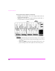


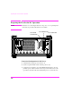


Table Of Contents
- 1 1 Getting Started With The Test Set
- 2 2 Measurements Considerations
- 3 3 Testing FM Radios
- FM Off The Air Monitoring/Determining Unknown Tran...
- FM Output Power, Deviation, and Frequency/Frequenc...
- FM Deviation and Symmetry Measurement
- FM Microphone Sensitivity and Modulation Limiting ...
- FM CTCSS Encoder Frequency and Deviation Measureme...
- FM CDCSS Coding and Deviation Measurements
- FM DTMF Encodes and Deviation Measurement
- FM Audio Distortion Measurement
- FM Harmonics and Spurious Output Measurement
- FM Audio Output Power Measurement
- FM SINAD, Receiver Center Frequency, and Modulatio...
- FM Variation Of Sensitivity With Signal Frequency ...
- FM 20 dB Quieting Sensitivity Measurement
- FM Critical and Maximum Squelch Sensitivity Measur...
- FM CTCSS Sensitivity and Bandwidth Measurement
- FM CDCSS Sensitivity Measurement
- FM Audio Frequency Response Measurement
- FM Audio Distortion Measurement
- FM Spurious Response Attenuation Measurement
- 4 4 Testing AM Radios
- AM Off The Air Monitoring/Determining Unknown Tran...
- AM Output Power, Deviation, and Frequency/Frequenc...
- AM Microphone Sensitivity and Modulation Limiting ...
- AM Audio Distortion Measurement
- AM Harmonics and Spurious Output Measurement
- AM Envelope Display Measurement
- AM Audio Output Power Measurement
- AM Sensitivity Measurement
- AM AGC Measurement
- AM Squelch Sensitivity Measurement
- AM Audio Frequency Response Measurement
- AM Audio Distortion Measurement
- AM Spurious Response Attenuation Measurement
- 5 5 Testing SSB Radios
- 6 6 Spectrum Analyzer Measurements
- Measuring Transmitter High/Low Power Signals
- Field Strength Measurements
- Analyzing External Transmitter Inter-modulation Di...
- Basic Measurements with the Tracking Generator
- Antenna Return Loss (VSWR) Measurement & Tuning
- 1/4 Wave Coaxial Filter Tuning (Swept)
- Cable Fault Locations
- Passive Cavity Insertion and Return Loss Measureme...
- Repeater System Effective Sensitivity Measurement
- 7 7 Oscilloscope Measurements
- 8 8 Configuring for Measurements
- 9 9 References
- 10 10 HP 8920A Specifications
- RF Frequency
- Output
- Spectral Purity
- FM
- AM
- TDMA Signal Generator
- Frequency
- Output Level
- RF Power Measurement
- RF Frequency Measurement
- FM Measurement
- AM Measurement
- SSB Measurement
- TDMA Analyzer
- Frequency Measurement
- AC Voltage Measurement
- DC Voltage Measurement
- Distortion Measurement
- SINAD Measurement
- Audio Filters
- Frequency
- Tracking Generator
- Adjacent Channel Power
- TCXO (Standard)
- OCXO (Option 001)
- 11 11 HP 8920B Specifications
- RF Frequency
- Output
- Spectral Purity
- FM
- AM
- TDMA Signal Generator
- Frequency
- Output Level
- RF Power Measurement
- RF Frequency Measurement
- FM Measurement
- AM Measurement
- SSB Measurement
- TDMA Analyzer
- Frequency Measurement
- AC Voltage Measurement
- DC Voltage Measurement
- Distortion Measurement
- SINAD Measurement
- Audio Filters
- Frequency
- Tracking Generator
- Adjacent Channel Power
- TCXO (Standard)
- OCXO (Option 001)

Preparing the Test Set for DC Operation
245
CABLING
RESTRICTIONS
When cabling the DC connector, remember that varying wire gauge,
type, and length will yield different resistive losses. Proper operation
of the Test Set requires that a minimum of 11 Vdc at 12 Adc be
present at the DC input connector. A typical DC connection should
consist of a cable made from 16 gauge stranded wire (20 feet in
length maximum) with a power source of 13.8 Vdc @ 15A.
4. Turn the POWER ON (in). After approximately 15 seconds, verify that the
CRT screen displays “All self tests passed” and that the “RX TEST” screen
is displayed.
If correct, the instrument is ready for operation.
NOTE: If DC power-up appears incorrect, turn OFF the POWER switch. Verify that
DC fuse is not blown. Replace if required.
Replacing a fuse with a different type, size, or rating than supplied with the
instrument can cause a fire hazard and/or electrical shock.