
User's Manual
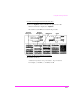


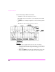
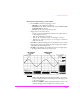
Table Of Contents
- 1 1 Getting Started With The Test Set
- 2 2 Measurements Considerations
- 3 3 Testing FM Radios
- FM Off The Air Monitoring/Determining Unknown Tran...
- FM Output Power, Deviation, and Frequency/Frequenc...
- FM Deviation and Symmetry Measurement
- FM Microphone Sensitivity and Modulation Limiting ...
- FM CTCSS Encoder Frequency and Deviation Measureme...
- FM CDCSS Coding and Deviation Measurements
- FM DTMF Encodes and Deviation Measurement
- FM Audio Distortion Measurement
- FM Harmonics and Spurious Output Measurement
- FM Audio Output Power Measurement
- FM SINAD, Receiver Center Frequency, and Modulatio...
- FM Variation Of Sensitivity With Signal Frequency ...
- FM 20 dB Quieting Sensitivity Measurement
- FM Critical and Maximum Squelch Sensitivity Measur...
- FM CTCSS Sensitivity and Bandwidth Measurement
- FM CDCSS Sensitivity Measurement
- FM Audio Frequency Response Measurement
- FM Audio Distortion Measurement
- FM Spurious Response Attenuation Measurement
- 4 4 Testing AM Radios
- AM Off The Air Monitoring/Determining Unknown Tran...
- AM Output Power, Deviation, and Frequency/Frequenc...
- AM Microphone Sensitivity and Modulation Limiting ...
- AM Audio Distortion Measurement
- AM Harmonics and Spurious Output Measurement
- AM Envelope Display Measurement
- AM Audio Output Power Measurement
- AM Sensitivity Measurement
- AM AGC Measurement
- AM Squelch Sensitivity Measurement
- AM Audio Frequency Response Measurement
- AM Audio Distortion Measurement
- AM Spurious Response Attenuation Measurement
- 5 5 Testing SSB Radios
- 6 6 Spectrum Analyzer Measurements
- Measuring Transmitter High/Low Power Signals
- Field Strength Measurements
- Analyzing External Transmitter Inter-modulation Di...
- Basic Measurements with the Tracking Generator
- Antenna Return Loss (VSWR) Measurement & Tuning
- 1/4 Wave Coaxial Filter Tuning (Swept)
- Cable Fault Locations
- Passive Cavity Insertion and Return Loss Measureme...
- Repeater System Effective Sensitivity Measurement
- 7 7 Oscilloscope Measurements
- 8 8 Configuring for Measurements
- 9 9 References
- 10 10 HP 8920A Specifications
- RF Frequency
- Output
- Spectral Purity
- FM
- AM
- TDMA Signal Generator
- Frequency
- Output Level
- RF Power Measurement
- RF Frequency Measurement
- FM Measurement
- AM Measurement
- SSB Measurement
- TDMA Analyzer
- Frequency Measurement
- AC Voltage Measurement
- DC Voltage Measurement
- Distortion Measurement
- SINAD Measurement
- Audio Filters
- Frequency
- Tracking Generator
- Adjacent Channel Power
- TCXO (Standard)
- OCXO (Option 001)
- 11 11 HP 8920B Specifications
- RF Frequency
- Output
- Spectral Purity
- FM
- AM
- TDMA Signal Generator
- Frequency
- Output Level
- RF Power Measurement
- RF Frequency Measurement
- FM Measurement
- AM Measurement
- SSB Measurement
- TDMA Analyzer
- Frequency Measurement
- AC Voltage Measurement
- DC Voltage Measurement
- Distortion Measurement
- SINAD Measurement
- Audio Filters
- Frequency
- Tracking Generator
- Adjacent Channel Power
- TCXO (Standard)
- OCXO (Option 001)

Using the Oscilloscope
237
to the RF IN/OUT or ANT IN connectors.
• Audio In for a signal connected to the AUDIO IN connector.
• Radio Int for a signal connected to the optional rear panel Radio Inter-
face connector.
• Ext Mod for a signal connected to the rear panel MODULATION IN-
PUT connector.
• Mic Mod for a signal connected to the MIC/ACC connector “MIC” pin.
• FM Mod for the FM modulated audio from the RF Gen section.
• AM Mod for the AM modulated audio from the RF Gen section.
• Audio Out for the signal present at the AUDIO OUT connector
5. Select from the Scope To field’s list of choices where in the AF Analyzer’s
circuitry the signal is routed to the Oscilloscope.
NOTE: All choices except Input are capacitive coupled. Use Input if the signal being
measured is ≤1Hz.
• Input to route the audio to the Oscilloscope without being processed.
• Filters to route the audio to the Oscilloscope after passing through Fil-
ters #1 and #2.
• De-emp to route the audio to the Oscilloscope after passing through Fil-
ters #1 and #2, and the De-Emphasis circuitry.
• Notch to route the audio to the Oscilloscope after passing through Fil-
ters #1 and #2, the De-Emphasis circuitry, and Notch circuitry.
6. Select the SCOPE screen.
7. Select the CONTROLS field.
8. Continue the measurement by selecting a control screen from the list of
choices and referring to the following:
• see "Measurements Using the Main Control Fields:" on page 238.
• see "Measurement Using the Trigger Control Fields:" on page 239.
• see "Measurements Using the Marker Control Fields:" on page
240.