
User's Manual
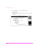
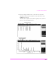
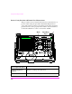

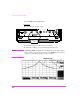
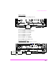
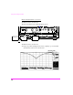

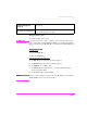
Table Of Contents
- 1 1 Getting Started With The Test Set
- 2 2 Measurements Considerations
- 3 3 Testing FM Radios
- FM Off The Air Monitoring/Determining Unknown Tran...
- FM Output Power, Deviation, and Frequency/Frequenc...
- FM Deviation and Symmetry Measurement
- FM Microphone Sensitivity and Modulation Limiting ...
- FM CTCSS Encoder Frequency and Deviation Measureme...
- FM CDCSS Coding and Deviation Measurements
- FM DTMF Encodes and Deviation Measurement
- FM Audio Distortion Measurement
- FM Harmonics and Spurious Output Measurement
- FM Audio Output Power Measurement
- FM SINAD, Receiver Center Frequency, and Modulatio...
- FM Variation Of Sensitivity With Signal Frequency ...
- FM 20 dB Quieting Sensitivity Measurement
- FM Critical and Maximum Squelch Sensitivity Measur...
- FM CTCSS Sensitivity and Bandwidth Measurement
- FM CDCSS Sensitivity Measurement
- FM Audio Frequency Response Measurement
- FM Audio Distortion Measurement
- FM Spurious Response Attenuation Measurement
- 4 4 Testing AM Radios
- AM Off The Air Monitoring/Determining Unknown Tran...
- AM Output Power, Deviation, and Frequency/Frequenc...
- AM Microphone Sensitivity and Modulation Limiting ...
- AM Audio Distortion Measurement
- AM Harmonics and Spurious Output Measurement
- AM Envelope Display Measurement
- AM Audio Output Power Measurement
- AM Sensitivity Measurement
- AM AGC Measurement
- AM Squelch Sensitivity Measurement
- AM Audio Frequency Response Measurement
- AM Audio Distortion Measurement
- AM Spurious Response Attenuation Measurement
- 5 5 Testing SSB Radios
- 6 6 Spectrum Analyzer Measurements
- Measuring Transmitter High/Low Power Signals
- Field Strength Measurements
- Analyzing External Transmitter Inter-modulation Di...
- Basic Measurements with the Tracking Generator
- Antenna Return Loss (VSWR) Measurement & Tuning
- 1/4 Wave Coaxial Filter Tuning (Swept)
- Cable Fault Locations
- Passive Cavity Insertion and Return Loss Measureme...
- Repeater System Effective Sensitivity Measurement
- 7 7 Oscilloscope Measurements
- 8 8 Configuring for Measurements
- 9 9 References
- 10 10 HP 8920A Specifications
- RF Frequency
- Output
- Spectral Purity
- FM
- AM
- TDMA Signal Generator
- Frequency
- Output Level
- RF Power Measurement
- RF Frequency Measurement
- FM Measurement
- AM Measurement
- SSB Measurement
- TDMA Analyzer
- Frequency Measurement
- AC Voltage Measurement
- DC Voltage Measurement
- Distortion Measurement
- SINAD Measurement
- Audio Filters
- Frequency
- Tracking Generator
- Adjacent Channel Power
- TCXO (Standard)
- OCXO (Option 001)
- 11 11 HP 8920B Specifications
- RF Frequency
- Output
- Spectral Purity
- FM
- AM
- TDMA Signal Generator
- Frequency
- Output Level
- RF Power Measurement
- RF Frequency Measurement
- FM Measurement
- AM Measurement
- SSB Measurement
- TDMA Analyzer
- Frequency Measurement
- AC Voltage Measurement
- DC Voltage Measurement
- Distortion Measurement
- SINAD Measurement
- Audio Filters
- Frequency
- Tracking Generator
- Adjacent Channel Power
- TCXO (Standard)
- OCXO (Option 001)
Using the Tracking Generator
224
17. Select Main from the Choices field.
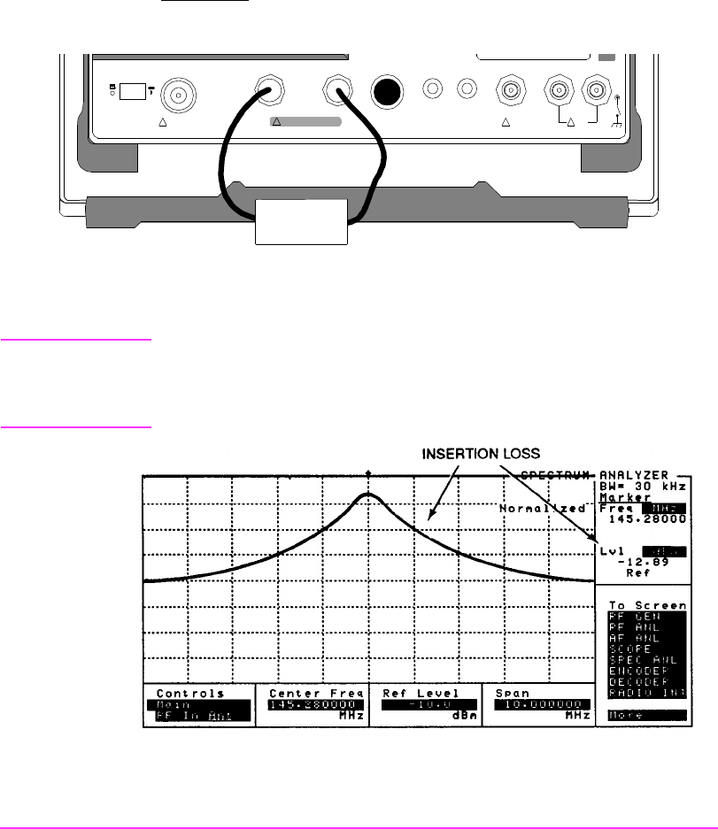
Pass Cavity:
18. Connect the pass cavity as shown.
19. Adjust the tuning rod to the desired pass frequency.
20. Adjust the coupling loops for desired band-pass/insertion loss.
NOTE: If Sensitivity dB/div is changed from 10 dB/div the coaxial cables must be
shorten, and the previous steps performed on the Auxiliary screen must be
repeated to re-normalize the display for the new setting.
AUDIO IN
LOHI
!
MAX
42 v Pk
!
MAX
12 v P k
AUDIO OUTSQUELCHVO LUMEMIC/ACC
MAX POWER 200 mW
!
ANT INDUPLEX OUTRF IN/OUT
!
MA X POWER 60 W
CONTINUOUS
POWER
OFF ON
Pass Cav-
ity