
User's Manual
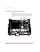
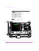
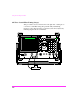
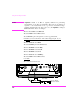
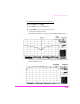
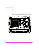
Table Of Contents
- 1 1 Getting Started With The Test Set
- 2 2 Measurements Considerations
- 3 3 Testing FM Radios
- FM Off The Air Monitoring/Determining Unknown Tran...
- FM Output Power, Deviation, and Frequency/Frequenc...
- FM Deviation and Symmetry Measurement
- FM Microphone Sensitivity and Modulation Limiting ...
- FM CTCSS Encoder Frequency and Deviation Measureme...
- FM CDCSS Coding and Deviation Measurements
- FM DTMF Encodes and Deviation Measurement
- FM Audio Distortion Measurement
- FM Harmonics and Spurious Output Measurement
- FM Audio Output Power Measurement
- FM SINAD, Receiver Center Frequency, and Modulatio...
- FM Variation Of Sensitivity With Signal Frequency ...
- FM 20 dB Quieting Sensitivity Measurement
- FM Critical and Maximum Squelch Sensitivity Measur...
- FM CTCSS Sensitivity and Bandwidth Measurement
- FM CDCSS Sensitivity Measurement
- FM Audio Frequency Response Measurement
- FM Audio Distortion Measurement
- FM Spurious Response Attenuation Measurement
- 4 4 Testing AM Radios
- AM Off The Air Monitoring/Determining Unknown Tran...
- AM Output Power, Deviation, and Frequency/Frequenc...
- AM Microphone Sensitivity and Modulation Limiting ...
- AM Audio Distortion Measurement
- AM Harmonics and Spurious Output Measurement
- AM Envelope Display Measurement
- AM Audio Output Power Measurement
- AM Sensitivity Measurement
- AM AGC Measurement
- AM Squelch Sensitivity Measurement
- AM Audio Frequency Response Measurement
- AM Audio Distortion Measurement
- AM Spurious Response Attenuation Measurement
- 5 5 Testing SSB Radios
- 6 6 Spectrum Analyzer Measurements
- Measuring Transmitter High/Low Power Signals
- Field Strength Measurements
- Analyzing External Transmitter Inter-modulation Di...
- Basic Measurements with the Tracking Generator
- Antenna Return Loss (VSWR) Measurement & Tuning
- 1/4 Wave Coaxial Filter Tuning (Swept)
- Cable Fault Locations
- Passive Cavity Insertion and Return Loss Measureme...
- Repeater System Effective Sensitivity Measurement
- 7 7 Oscilloscope Measurements
- 8 8 Configuring for Measurements
- 9 9 References
- 10 10 HP 8920A Specifications
- RF Frequency
- Output
- Spectral Purity
- FM
- AM
- TDMA Signal Generator
- Frequency
- Output Level
- RF Power Measurement
- RF Frequency Measurement
- FM Measurement
- AM Measurement
- SSB Measurement
- TDMA Analyzer
- Frequency Measurement
- AC Voltage Measurement
- DC Voltage Measurement
- Distortion Measurement
- SINAD Measurement
- Audio Filters
- Frequency
- Tracking Generator
- Adjacent Channel Power
- TCXO (Standard)
- OCXO (Option 001)
- 11 11 HP 8920B Specifications
- RF Frequency
- Output
- Spectral Purity
- FM
- AM
- TDMA Signal Generator
- Frequency
- Output Level
- RF Power Measurement
- RF Frequency Measurement
- FM Measurement
- AM Measurement
- SSB Measurement
- TDMA Analyzer
- Frequency Measurement
- AC Voltage Measurement
- DC Voltage Measurement
- Distortion Measurement
- SINAD Measurement
- Audio Filters
- Frequency
- Tracking Generator
- Adjacent Channel Power
- TCXO (Standard)
- OCXO (Option 001)
Using the Tracking Generator
218
Cable Fault Locations
This procedure is used to locate breaks in coaxial cables using the
Spectrum Analyzer/Tracking Generator option and System Support
Software Test Card, HP 11807A option 100. Suspected faults are
displayed as data (indicating the fault length) or plotted on the screen.
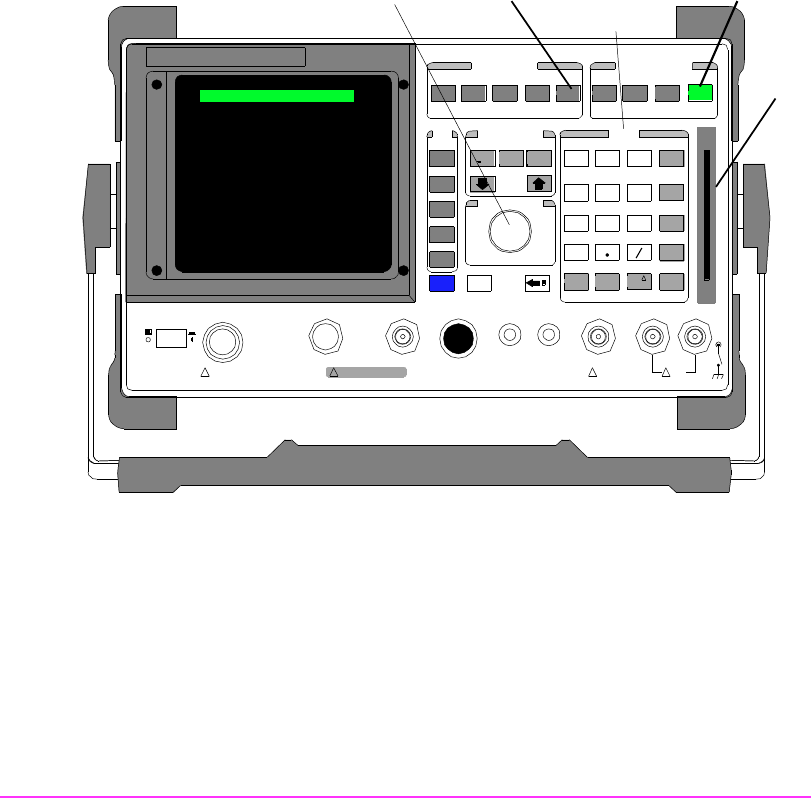
DUPLEXTXRX PREV TESTS
CONFIGHELPMSSG HOLD P RINT
SCREEN CONTROL
LOCAL
ADRS
RECALL
SAVE
MEAS
RESET
PRESET
INSTRUMENT STATE
DATA FUNCTIONS
IN CR
: 10
REF SET
INCR
SET
METER
INCR X10
AVG
LO LIMIT HI LIMIT
CURSOR CONTROL
PUSH TO SELECT
CANCEL
SHIFT
k1
k1’
k2
k2’
k3
k3’
k4
ASSIGN
k5
RELEASE
USER DATA
789
456
123
0
+
_
ENTER
GHz
dBm
dB
MHz
V
%
kHz
mV
s
Hz
µV
ms
%
dBµV
Ω
ppm
W
NO
ON/OF F
YES
MEM ORY
CAR D
AUDIO IN
LOHI
!
MAX
42 v P k
!
MAX
12 v Pk
AUDIO OUTSQUELCHVO LUMEMIC/ACC
MAX PO WER 200 m W
!
ANT IN
DUPLEX OUTRF IN/OUT
!
MAX POWER 60 W
CONTINUOUS
POWE R
OFF ON
1
2
3
Keys
Data Entry
SPECTRUM ANALYZER
Knob