
User's Manual
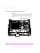
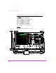
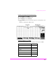
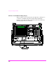
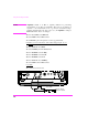
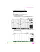
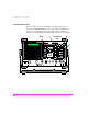
Table Of Contents
- 1 1 Getting Started With The Test Set
- 2 2 Measurements Considerations
- 3 3 Testing FM Radios
- FM Off The Air Monitoring/Determining Unknown Tran...
- FM Output Power, Deviation, and Frequency/Frequenc...
- FM Deviation and Symmetry Measurement
- FM Microphone Sensitivity and Modulation Limiting ...
- FM CTCSS Encoder Frequency and Deviation Measureme...
- FM CDCSS Coding and Deviation Measurements
- FM DTMF Encodes and Deviation Measurement
- FM Audio Distortion Measurement
- FM Harmonics and Spurious Output Measurement
- FM Audio Output Power Measurement
- FM SINAD, Receiver Center Frequency, and Modulatio...
- FM Variation Of Sensitivity With Signal Frequency ...
- FM 20 dB Quieting Sensitivity Measurement
- FM Critical and Maximum Squelch Sensitivity Measur...
- FM CTCSS Sensitivity and Bandwidth Measurement
- FM CDCSS Sensitivity Measurement
- FM Audio Frequency Response Measurement
- FM Audio Distortion Measurement
- FM Spurious Response Attenuation Measurement
- 4 4 Testing AM Radios
- AM Off The Air Monitoring/Determining Unknown Tran...
- AM Output Power, Deviation, and Frequency/Frequenc...
- AM Microphone Sensitivity and Modulation Limiting ...
- AM Audio Distortion Measurement
- AM Harmonics and Spurious Output Measurement
- AM Envelope Display Measurement
- AM Audio Output Power Measurement
- AM Sensitivity Measurement
- AM AGC Measurement
- AM Squelch Sensitivity Measurement
- AM Audio Frequency Response Measurement
- AM Audio Distortion Measurement
- AM Spurious Response Attenuation Measurement
- 5 5 Testing SSB Radios
- 6 6 Spectrum Analyzer Measurements
- Measuring Transmitter High/Low Power Signals
- Field Strength Measurements
- Analyzing External Transmitter Inter-modulation Di...
- Basic Measurements with the Tracking Generator
- Antenna Return Loss (VSWR) Measurement & Tuning
- 1/4 Wave Coaxial Filter Tuning (Swept)
- Cable Fault Locations
- Passive Cavity Insertion and Return Loss Measureme...
- Repeater System Effective Sensitivity Measurement
- 7 7 Oscilloscope Measurements
- 8 8 Configuring for Measurements
- 9 9 References
- 10 10 HP 8920A Specifications
- RF Frequency
- Output
- Spectral Purity
- FM
- AM
- TDMA Signal Generator
- Frequency
- Output Level
- RF Power Measurement
- RF Frequency Measurement
- FM Measurement
- AM Measurement
- SSB Measurement
- TDMA Analyzer
- Frequency Measurement
- AC Voltage Measurement
- DC Voltage Measurement
- Distortion Measurement
- SINAD Measurement
- Audio Filters
- Frequency
- Tracking Generator
- Adjacent Channel Power
- TCXO (Standard)
- OCXO (Option 001)
- 11 11 HP 8920B Specifications
- RF Frequency
- Output
- Spectral Purity
- FM
- AM
- TDMA Signal Generator
- Frequency
- Output Level
- RF Power Measurement
- RF Frequency Measurement
- FM Measurement
- AM Measurement
- SSB Measurement
- TDMA Analyzer
- Frequency Measurement
- AC Voltage Measurement
- DC Voltage Measurement
- Distortion Measurement
- SINAD Measurement
- Audio Filters
- Frequency
- Tracking Generator
- Adjacent Channel Power
- TCXO (Standard)
- OCXO (Option 001)
Using the Tracking Generator
210
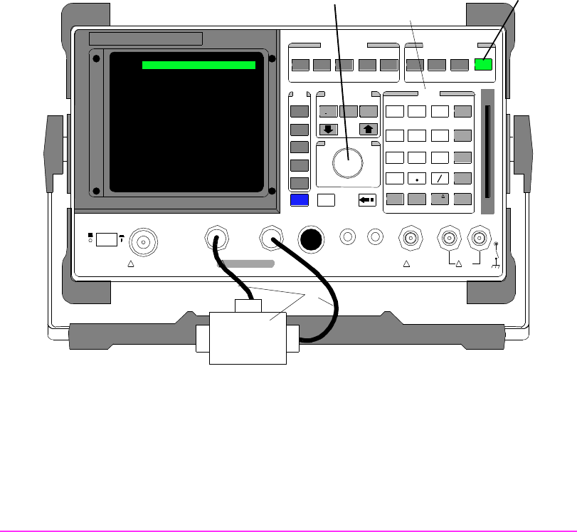
Antenna Return Loss (VSWR) Measurement & Tuning
Description
This procedure is used to measure the return loss of an antenna through
a directional bridge and the Spectrum Analyzer/Tracking Generator
option. Return loss is measured and can be converted into VSWR using
a table.
DUPLEXTXRX PREV TESTS
CO NFIGHELPMSSG HOLD PRINT
SCREEN CONTROL
LOCAL
ADRS
REC ALL
SAVE
MEAS
RES ET
PRESET
INSTRUMENT STATE
DATA FUNCTIONS
INCR
: 10
REF SET
INCR
SET
METER
INCR X10
AVG
LO LIMIT HI LIMIT
CURSOR CONTROL
PUSH TO SELECT
CA NCEL
SHIF T
k1
k1’
k2
k2’
k3
k3’
k4
ASSIGN
k5
RELEASE
USER DATA
789
456
123
0
+
_
ENTER
GHz
dBm
dB
MHz
V
%
kH z
mV
s
Hz
µV
ms
%
dBµV
Ω
ppm
W
NO
ON/OFF
YES
MEMOR Y
CAR D
AUDIO IN
LOHI
!
MAX
42 v Pk
!
MAX
12 v P k
AUDIO OUTSQUELCHVO LUMEMIC/ACC
MAX POWER 200 mW
!
ANT INDUPLEX OUTRF IN/OUT
!
MA X POWER 60 W
CONTINUOUS
POWER
OFF ON
2
Knob
SPECTRUM ANALYZER
Data Entry
Keys
1
Return Loss Bridge or Directional Coupler
Reflected
Source