
User's Manual
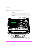
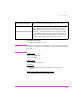
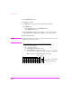
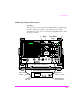
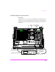
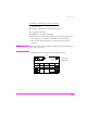
Table Of Contents
- 1 1 Getting Started With The Test Set
- 2 2 Measurements Considerations
- 3 3 Testing FM Radios
- FM Off The Air Monitoring/Determining Unknown Tran...
- FM Output Power, Deviation, and Frequency/Frequenc...
- FM Deviation and Symmetry Measurement
- FM Microphone Sensitivity and Modulation Limiting ...
- FM CTCSS Encoder Frequency and Deviation Measureme...
- FM CDCSS Coding and Deviation Measurements
- FM DTMF Encodes and Deviation Measurement
- FM Audio Distortion Measurement
- FM Harmonics and Spurious Output Measurement
- FM Audio Output Power Measurement
- FM SINAD, Receiver Center Frequency, and Modulatio...
- FM Variation Of Sensitivity With Signal Frequency ...
- FM 20 dB Quieting Sensitivity Measurement
- FM Critical and Maximum Squelch Sensitivity Measur...
- FM CTCSS Sensitivity and Bandwidth Measurement
- FM CDCSS Sensitivity Measurement
- FM Audio Frequency Response Measurement
- FM Audio Distortion Measurement
- FM Spurious Response Attenuation Measurement
- 4 4 Testing AM Radios
- AM Off The Air Monitoring/Determining Unknown Tran...
- AM Output Power, Deviation, and Frequency/Frequenc...
- AM Microphone Sensitivity and Modulation Limiting ...
- AM Audio Distortion Measurement
- AM Harmonics and Spurious Output Measurement
- AM Envelope Display Measurement
- AM Audio Output Power Measurement
- AM Sensitivity Measurement
- AM AGC Measurement
- AM Squelch Sensitivity Measurement
- AM Audio Frequency Response Measurement
- AM Audio Distortion Measurement
- AM Spurious Response Attenuation Measurement
- 5 5 Testing SSB Radios
- 6 6 Spectrum Analyzer Measurements
- Measuring Transmitter High/Low Power Signals
- Field Strength Measurements
- Analyzing External Transmitter Inter-modulation Di...
- Basic Measurements with the Tracking Generator
- Antenna Return Loss (VSWR) Measurement & Tuning
- 1/4 Wave Coaxial Filter Tuning (Swept)
- Cable Fault Locations
- Passive Cavity Insertion and Return Loss Measureme...
- Repeater System Effective Sensitivity Measurement
- 7 7 Oscilloscope Measurements
- 8 8 Configuring for Measurements
- 9 9 References
- 10 10 HP 8920A Specifications
- RF Frequency
- Output
- Spectral Purity
- FM
- AM
- TDMA Signal Generator
- Frequency
- Output Level
- RF Power Measurement
- RF Frequency Measurement
- FM Measurement
- AM Measurement
- SSB Measurement
- TDMA Analyzer
- Frequency Measurement
- AC Voltage Measurement
- DC Voltage Measurement
- Distortion Measurement
- SINAD Measurement
- Audio Filters
- Frequency
- Tracking Generator
- Adjacent Channel Power
- TCXO (Standard)
- OCXO (Option 001)
- 11 11 HP 8920B Specifications
- RF Frequency
- Output
- Spectral Purity
- FM
- AM
- TDMA Signal Generator
- Frequency
- Output Level
- RF Power Measurement
- RF Frequency Measurement
- FM Measurement
- AM Measurement
- SSB Measurement
- TDMA Analyzer
- Frequency Measurement
- AC Voltage Measurement
- DC Voltage Measurement
- Distortion Measurement
- SINAD Measurement
- Audio Filters
- Frequency
- Tracking Generator
- Adjacent Channel Power
- TCXO (Standard)
- OCXO (Option 001)

AM Transmitters
134
Measurement Procedure:
1. Connect the Transmitter as shown.
CAUTION: The RF present at the Test Set RF IN/OUT connector must not exceed 60W
continuous (or 100 Watts for 10 sec/minute) or permanent instrument damage
may result.
On the Test Set:
2. Press the PRESET key.
3. Press the TX key.
On the Radio:
4. Key the Transmitter.
On the Test Set using the knob and data entry keys:
5. Set AF Anl In to AM Demod.
6. Adjust AFGen1 Lvl until AM Depth is 80%.
On the Radio:
7. Un-key the Transmitter.
Tune Mode
To Screen
TX TEST
AM Depth
Auto/Manual
TX Frequency
TX Power
Tune Freq
27.065000
MHz
IF Filter
230 kHz
Input Port
RF In/Ant
AF Anl In
SSB Demod
Filter 1
<20Hz HPF
Filter 2
>99kHz LPF
De-Emphasis
750 us/Off
Detector
Pk+-Max
Ext TX Key
On/Off
TX Pwr Zero
Zero
AFGen1 Lvl
830
mV
AF Freq
RF GEN
RF ANL
AF ANL
SCOPE
SPEC ANL
ENCODER
DECODER
RADIO INT
More
AFGen1 Freq
1.0000
kHz
kHz
%
W
MHz
27.064762
4.58 1.00001
78.3
AM Depth