
User's Manual

249
Chapter 5, Advanced Operations
Status Reporting
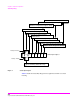
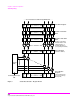
Status Reporting Structure Operation.
In general the status reporting structure described on the previous pages is used as
follows:
• Determine which conditions, as defined by their bit positions in the Condition Register,
should cause the Summary Message to be set TRUE if they occur.
For example, Condition Register Bit 3 = Overpower Protection Tripped
• Determine the polarity of the bit-state transition which will indicate the condition has
occurred.
For example,
logic 0 = Overpower Protection not tripped
logic 1 = Overpower Protection tripped
occurrence indicated by a 0 to 1 transition
use positive transition (PTR) filter for bit 3
• Set the Transition Filters to the correct polarity to pass the bit-state transition to the
Event Register.
For example,
Set Positive Transition Filter bit 3 to 1, all other bits to 0.
Set Negative Transition Filter bit 3 to 0, all other bits to 0.
• Set the correct bits in the Enable Register to generate the Summary Message if the
condition has been latched into the Event Register.
For example,
Set bit 3 of the Enable Register to a logic 1, all other bits to 0.
• Repeat these steps for any register containing the Summary Message bit.