Agilent Technologies 8920A RF Communications Test Set Programmer’s Guide Firmware Version A.18.
© Copyright Agilent Technologies 1997, 2000 Notice No part of this manual may be reproduced in any form or by any means (including electronic storage and retrieval or translation into a foreign language) without prior agreement and written consent from Agilent Technologies Inc. as governed by United States and international copyright laws. The material contained in this document is subject to change without notice.
Safety Summary The following general safety precautions must be observed during all phases of operation of this instrument. Failure to comply with these precautions or with specific warnings elsewhere in this manual violates safety standards of design, manufacture, and intended use of the instrument. Agilent Technologies Inc. assumes no liability for the customer’s failure to comply with these requirements. GENERAL This product is a Safety Class 1 instrument (provided with a protective earth terminal).
GROUND THE INSTRUMENT To minimize shock hazard, the instrument chassis and cover must be connected to an electrical protective earth ground. The instrument must be connected to the ac power mains through a grounded power cable, with the ground wire firmly connected to an electrical ground (safety ground) at the power outlet. Any interruption of the protective (grounding) conductor or disconnection of the protective earth terminal will cause a potential shock hazard that could result in personal injury.
Safety Symbols Caution, refer to accompanying documents Warning, risk of electric shock Earth (ground) terminal Alternating current Frame or chassis terminal Standby (supply). Units with this symbol are not completely disconnected from ac mains when this switch is off. To completely disconnect the unit from ac mains, either disconnect the power cord, or have a qualified electrician install an external switch. Product Markings CE - the CE mark is a registered trademark of the European Community.
Agilent Technologies Warranty Statement for Commercial Products Agilent Technologies 8920A RF Communications Test Set Duration of Warranty: 1 year 1. Agilent Technologies warrants Agilent Technologies hardware, accessories and supplies against defects in materials and workmanship for the period specified above. If Agilent Technologies receives notice of such defects during the warranty period, Agilent Technologies will, at its option, either repair or replace products which prove to be defective.
8. Agilent Technologies will be liable for damage to tangible property per incident up to the greater of $300,000 or the actual amount paid for the product that is the subject of the claim, and for damages for bodily injury or death, to the extent that all such damages are determined by a court of competent jurisdiction to have been directly caused by a defective Agilent Technologies product. 9.
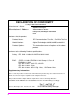
DECLARATION OF CONFORMITY according to ISO/IEC Guide 22 and EN 45014 Manufacturer’s Name: Manufacturer’s Address: Agilent Technologies 24001 E. Mission Avenue Liberty Lake, Washington 99019-9599 USA declares that the product Product Name: RF Communications Test Set / Cell Site Test Set Model Number: Agilent Technologies 8920A, 8920B , and 8921A Product Options: This declaration covers all options of the above product.
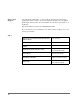
Table 1 Regional Sales Offices United States of America: Agilent Technologies Test and Measurement Call Center P.O. Box 4026 Englewood, CO 80155-4026 Canada: Agilent Technologies Canada Inc. 5150 Spectrum Way Mississauga, Ontario L4W 5G1 (tel) 1 800 452 4844 (tel) 1 877 894 4414 Europe: Agilent Technologies European Marketing Organization P.O. Box 999 1180 AZ Amstelveen The Netherlands (tel) (3120) 547 9999 Japan: Agilent Technologies Japan Ltd.
Service and Support Any adjustment, maintenance, or repair of this product must be performed by qualified personnel. Contact your customer engineer through your local Agilent Technologies Service Center. You can find a list of local service representatives on the Web at: http://www.agilent-tech.com/services/English/index.
Manufacturer’s Declaration This statement is provided to comply with the requirements of the German Sound Emission Directive, from 18 January 1991. This product has a sound pressure emission (at the operator position) < 70 dB(A). • • • • Sound Pressure Lp < 70 dB(A). At Operator Position. Normal Operation. According to ISO 7779:1988/EN 27779:1991 (Type Test). Herstellerbescheinigung Diese Information steht im Zusammenhang mit den Anforderungen der Maschinenlärminformationsverordnung vom 18 Januar 1991.
Chapter 7, IBASIC Controller, describes how to develop Instrument BASIC (IBASIC) programs for use on the Test Set’s built-in IBASIC Controller. Topics discussed are: interfacing to the IBASIC Controller using the serial ports, overview of the three program development methods, entering and editing IBASIC programs, program control using the PROGram Subsystem, and an introduction to writing programs for the TESTS subsystem.
Contents 1 Using GPIB Overview of the Test Set Getting Started 34 Remote Operation Addressing 26 47 49 IEEE 488.
Contents 2 Methods For Reading Measurement Results Background 58 HP® BASIC ‘ON TIMEOUT’ Example Program 60 HP® BASIC ‘MAV’ Example Program 64 14
Contents 3 GPIB Command Guidelines Sequential and Overlapped Commands Guidelines for Operation 70 71 15
Contents 4 GPIB Commands GPIB Syntax Diagrams 92 Adjacent Channel Power (ACP) AF Analyzer 95 97 AF Generator 1 100 AF Generator 2 Pre-Modulation Filters AF Generator 2/Encoder Configure, I/O Configure 102 117 Call Processing 122 Decoder 141 Display 145 Measure 147 Oscilloscope Program 154 159 Save/Recall Registers RF Analyzer 160 161 RF Generator Radio Interface 163 164 Spectrum Analyzer 165 GPIB Only Commands 167 16 101
Contents Status 168 System 169 Tests Trigger 170 173 Integer Number Setting Syntax Real Number Setting Syntax 174 175 Multiple Real Number Setting Syntax Number Measurement Syntax 177 Multiple Number Measurement Syntax Equivalent Front-Panel Key Commands IEEE 488.
Contents 5 Advanced Operations Increasing Measurement Throughput Status Reporting 239 GPIB Service Requests Instrument Initialization Passing Control 18 313 293 303 234
Contents 6 Memory Cards/Mass Storage Default File System 324 Mass Storage Device Overview 325 Default Mass Storage Locations 331 Mass Storage Access 333 DOS and LIF File System Considerations Using the ROM Disk 340 Using Memory Cards 341 Backing Up Procedure and Library Files Copying Files Using IBASIC Commands Using RAM Disk 334 346 347 349 Using External Disk Drives 351 19
Contents 7 IBASIC Controller Introduction 354 The IBASIC Controller Screen 355 Important Notes for Program Development Program Development 357 358 Interfacing to the IBASIC Controller using Serial Ports Choosing Your Development Method 360 373 Method #1. Program Development on an External BASIC Language Computer 375 Method #2. Developing Programs on the Test Set Using the IBASIC EDIT Mode 381 Method #3.
Contents 8 Programming the Call Processing Subsystem Description of the Call Processing Subsystem’s Remote User Interface 426 Using the Call Processing Subsystem’s Remote User Interface 429 Programming the CALL CONTROL Screen 439 Programming the CALL DATA Screen 464 CALL DATA Screen Message Field Descriptions 468 Programming the CALL BIT Screen 478 CALL BIT Screen Message Field Descriptions 487 Programming the ANALOG MEAS Screen 510 Programming the CALL CONFIGURE Screen 517 Example Programs 520 21
Contents 9 Error Messages 22
Contents Index 569 23
Contents 24
1 Using GPIB1 1. GPIB was formerly called HP-IB for Hewlett-Packard instruments. Some labels on the instrument may still reflect the former HP® name.
Chapter 1, Using GPIB Overview of the Test Set Overview of the Test Set The Test Set combines up to 22 separate test instruments and an Instrument BASIC (IBASIC) Controller into one package. All of the Test Set’s functions can be automatically controlled through application programs running on the built-in IBASIC Controller or on an external controller connected through GPIB. Developing programs for the Test Set is simplified if the programmer has a basic understanding of how the Test Set operates.
Chapter 1, Using GPIB Overview of the Test Set Manual Control Mode The Test Set’s primary instruments are shown on the left side of Figure 1. There are two classes of instruments in the Test Set: signal analyzers (RF Analyzer, AF Analyzer, Oscilloscope, Spectrum Analyzer, Signaling Decoder) and signal sources (RF Generator, AF Generator #1, AF Generator #2/Signaling Encoder).
Chapter 1, Using GPIB Overview of the Test Set Internal Automatic Control Mode In Internal Automatic Control mode the Test Set’s operation is controlled by an application program running on the built-in Instrument BASIC (IBASIC) Controller. The built-in controller runs programs written in IBASIC, a subset of the HP® BASIC programming language used on the HP® 9000 Series 200/300 System Controllers. IBASIC is the only programming language supported on the built-in IBASIC Controller.
Chapter 1, Using GPIB Overview of the Test Set Differences Between the Test Set’s IBASIC Controller and Other Single-Tasking Controllers The IBASIC Controller is unlike other single tasking instrumentation controllers in several ways. First, it does not have a keyboard. This imposes some limitations on creating and editing IBASIC programs directly on the Test Set.
Chapter 1, Using GPIB Overview of the Test Set External Automatic Control Mode In External Automatic Control mode the Test Set’s operation is controlled by an external controller connected to the Test Set through the GPIB interface. When in External Automatic Control mode the Test Set’s internal configuration is the same as in Manual Control Mode with two exceptions: 1.
Chapter 1, Using GPIB Overview of the Test Set Writing programs for the Test Set One of the design goals for automatic control of the Test Set was that it operate the same way programmatically as it does manually. This is a key point to remember when developing programs for the Test Set. The benefit of this approach is that to automate a particular task, one need only figure out how to do the task manually and then duplicate the same process in software.
Figure 1 Manual Control Mode 32 S:\agilent\8920\8920b\PRGGUIDE\BOOK\CHAPTERS\usehpib.
Figure 2 TOP BOXES SIGNALING DECODER RF ANALYZER SPECTRUM ANALYZER OSCILLOSCOPE AF ANALYZER SIGNALING ENCODER FUNCTION GEN AF GEN #2 AF GEN #1 RF GEN TO SCREEN CONTROL HARDWARE INSTRUMENT CONTROL HARDWARE FRONT PANEL INFORMATION INSTRUMENT SETUP INFORMATION MEASUREMENT RESULTS AND DUT DATA GPIB #8 IBASIC CONTROLLER GPIB #7 PARALLEL PRINTER #15 SERIAL I/F #9 SERIAL I/F #10 ROM DISK MEMORY CARD KEYPAD/ ROTARY KNOB CRT FRONT PANEL Chapter 1, Using GPIB Overview of the Test Set Inter
Chapter 1, Using GPIB Getting Started Getting Started What is GPIB? The General Purpose Interface Bus (GPIB) is an implementation of the IEEE 488.1-1987 Standard Digital Interface for Programmable Instrumentation. Incorporation of the GPIB into the Test Set provides several valuable capabilities: • Programs running in the Test Set’s IBASIC Controller can control all the Test Set’s functions using its internal GPIB. This capability provides a single-instrument automated test system.
Chapter 1, Using GPIB Getting Started GPIB Information Provided in This Manual What Is Explained • How to configure the Test Set for GPIB operation • How to make an instrument setting over GPIB • How to read-back instrument settings over GPIB • How to make measurements over GPIB • How to connect external PCs, terminals or controllers to the Test Set • GPIB command syntax for the Test Set • IBASIC program development • IBASIC program transfer over GPIB • Various advanced functions such as,
Chapter 1, Using GPIB Getting Started General GPIB Programming Guidelines The following guidelines should be considered when developing programs which control the Test Set through GPIB: • Guideline #1. Avoid using the TX TEST and RX TEST screens. The RX TEST and TX TEST screens are specifically designed for manual testing of land mobile FM radios and, when displayed, automatically configure six “priority” fields in the Test Set for this purpose.
Chapter 1, Using GPIB Getting Started 2. When entering the TX TEST screen, a. The AF Anl In field, the De-Emphasis field, the Detector field and the AF Analyzer Measurement field (measurement displayed in upper, right portion of CRT display) are, • • • set to their preset values upon entering the screen for the first time since power-up, OR set to their preset values if the PRESET key is selected, OR set to the last setting made while in the screen b.
Chapter 1, Using GPIB Getting Started • Guideline #2. When developing programs to make measurements always follow this recommended sequence: 1. Bring the Test Set to its preset state using the front-panel PRESET key. This initial step allows you to start developing the measurement sequence with most fields in a known state. 2. Make the measurement manually using the front-panel controls of the Test Set. Record, in sequential order, the screens selected and the settings made within each screen.
Chapter 1, Using GPIB Getting Started 7. Send the MEASure query command to initiate a reading. This will place the measured value into the Test Set’s Output Queue. NOTE: When making AF Analyzer SINAD, Distortion, Signal to Noise Ratio, AF Frequency, DC Level, or Current measurements, the measurement type must first be selected using the SELect command. For example, MEAS:AFR:SEL'SINAD' followed by MEAS:AFR:SINAD? 8.
Chapter 1, Using GPIB Getting Started • Guideline #3. Avoid program hangs. If the program stops or “hangs up” when trying to ENTER a measured value, it is most likely that the desired measurement field is not available. There are several reasons that can happen: 1. The screen where the measurement field is located has not been DISPlayed before querying the measurement field. 2. The measurement is not turned ON. 3. The squelch control is set too high.
Chapter 1, Using GPIB Getting Started • Guideline #4. Use single quotes and spaces properly. The syntax diagrams in Chapter 4, “GPIB Commands,” show where single quotes are needed and where spaces are needed. Example OUTPUT 714;"DISPAFAN" OUTPUT 714;"AFAN:DEMP’Off’" Improper use of single quotes and spaces will cause, HP-IB Error:-103 Invalid Separator • Guideline #5. Ensure that settable fields are active by using the STATe ON command.
Chapter 1, Using GPIB Getting Started • Guideline #6. Numeric values are returned in GPIB Units or Attribute Units only. When querying measurements or settings through GPIB, the Test Set always returns numeric values in GPIB Units or Attribute Units, regardless of the current Display Units setting. GPIB Units, Attribute Units and Display Units determine the units-ofmeasure used for a measurement or setting, for example, Hz, Volts, Watts, Amperes, Ohms.
Chapter 1, Using GPIB Getting Started Preparing the Test Set For GPIB Use 1. If other GPIB devices are in the system, attach a GPIB cable from the Test Set’s rearpanel GPIB connector to any one of the other devices in the test system. 2. Access the I/O CONFIGURE screen and perform the following steps: a. Set the Test Set’s GPIB address using the HP-IB Adrs field. b. Set the Test Set’s GPIB Controller capability using the Mode field.
Chapter 1, Using GPIB Getting Started Using the GPIB with the Test Set’s built-in IBASIC Controller The Test Set has two GPIB interfaces, an internal-only GPIB at select code 8 and an external GPIB at select code 71. The GPIB at select code 8 is only available to the built-in IBASIC Controller and is used exclusively for communication between the IBASIC Controller and the Test Set. The GPIB at select code 71 serves three purposes: 1. It allows the Test Set to be controlled by an external controller 2.
Chapter 1, Using GPIB Getting Started Basic Programming Examples The following simple examples illustrate the basic approach to controlling the Test Set through the GPIB. The punctuation and command syntax used for these examples is given in Chapter 4, “GPIB Commands.”. The bus address 714 used in the following BASIC language examples assumes a GPIB interface at select code 7, and a Test Set GPIB address of 14. All examples assume an external controller is being used.
Chapter 1, Using GPIB Getting Started The following example reads several fields. Example OUTPUT 714;"DISP AFAN"!Display the AF Analyzer screen. OUTPUT 714;"AFAN:INP?"!Query the AF Anl In field ENTER 714;Af_input$ !Enter returned value into a string ariable. OUTPUT 714;"DISP RFG"!Display the RF Generator screen OUTPUT 714;"RFG:FREQ?"!Query the RF Gen Frequency field.
Chapter 1, Using GPIB Remote Operation Remote Operation The Test Set can be operated remotely through the General Purpose Interface Bus (GPIB). Except as otherwise noted, the Test Set complies with the IEEE 488.1-1987 and IEEE 488.2-1987 Standards. Bus compatibility, programming and data formats are described in the following sections. All front-panel functions, except those listed in Table 4, are programmable through GPIB.
Chapter 1, Using GPIB Remote Operation Remote Capabilities Conformance to the IEEE 488.1-1987 Standard For all IEEE 488.1 functions implemented, the Test Set adheres to the rules and procedures as outlined in that Standard. Conformance to the IEEE 488.2-1987 Standard For all IEEE 488.2 functions implemented, the Test Set adheres to the rules and procedures as outlined in that Standard with the exception of the *OPC Common Command. Refer to the *OPC Common Command description. IEEE 488.
Chapter 1, Using GPIB Addressing Addressing Factory Set Address The Test Set’s GPIB address is set to decimal 14 at the factory. The address can be changed by following the instructions in “Setting the Test Set’s Bus Address” on page 49. Extended Addressing Extended addressing (secondary command) capability is not implemented in the Test Set. Multiple Addressing Multiple addressing capability is not implemented in the Test Set.
Chapter 1, Using GPIB IEEE 488.1 Remote Interface Message Capabilities IEEE 488.1 Remote Interface Message Capabilities The remote interface message capabilities of the Test Set and the associated IEEE 488.1 messages and control lines are listed in Table 6. Table 6 Message Type Test Set IEEE 488.1 Interface Message Capability IEEE 488.1 Message Implemented Response Data Yes All front-panel functions, except those listed in Table 4 on page 47, are programmable.
Chapter 1, Using GPIB IEEE 488.1 Remote Interface Message Capabilities Table 6 Message Type Test Set IEEE 488.1 Interface Message Capability (Continued) IEEE 488.1 Message Implemented Response Clear Lockout/ Set Local Yes The Test Set returns to local mode (front-panel control) and local lockout is cleared when the REN bus control line goes false.
Chapter 1, Using GPIB IEEE 488.1 Remote Interface Message Capabilities Table 6 Message Type Test Set IEEE 488.1 Interface Message Capability (Continued) IEEE 488.1 Message Implemented Response Trigger Yes If in remote programming mode and addressed to listen, the Test Set makes a triggered measurement following the trigger conditions currently in effect in the instrument. The Test Set responds equally to the Group Execute Trigger (GET) bus command or the *TRG Common Command.
Chapter 1, Using GPIB Remote/Local Modes Remote/Local Modes Remote Mode In Remote mode all front-panel keys are disabled (except for the LOCAL key, POWER switch, Volume control and Squelch control). The LOCAL key is only disabled by the Local Lockout bus command. When in Remote mode and addressed to Listen the Test Set responds to the Data, Remote, Local, Clear (SDC), and Trigger messages.
Chapter 1, Using GPIB Remote/Local Modes Local To Remote Transitions The Test Set switches from Local to Remote mode upon receipt of the Remote message (REN bus line true and Test Set is addressed to listen). No instrument settings are changed by the transition from Local to Remote mode, but triggering is set to the state it was last set to in Remote mode (if no previous setting, the default is FULL SETTling and REPetitive RETRiggering).
Chapter 1, Using GPIB Remote/Local Modes Local Lockout The Local Lockout mode disables the front-panel LOCAL key and allows return to Local mode only by commands from the System Controller (Clear Lockout/Set Local message). When a data transmission to the Test Set is interrupted, which can happen if the LOCAL key is pressed, the data being transmitted may be lost. This can leave the Test Set in an unknown state.
Chapter 1, Using GPIB Remote/Local Modes 56 S:\agilent\8920\8920b\PRGGUIDE\BOOK\CHAPTERS\usehpib.
2 Methods For Reading Measurement Results 57
Chapter 2, Methods For Reading Measurement Results Background Background One of the most common remote user interface operations performed on an Test Set is to query and read a measurement result. Generally, this operation is accomplished by sending the query command to the Test Set, followed immediately by a request to read the requested measurement result.
Chapter 2, Methods For Reading Measurement Results Background This situation can be avoided entirely by: 1. sending a Selected Device Clear (SDC) interface message to put the Test Set’s GPIB subsystem into a known state. 2. sending a command to terminate the requested measurement cycle. These commands issued in this order will allow the control program to regain control of the Test Set. Any other sequence of commands will result in unexpected operation.
Chapter 2, Methods For Reading Measurement Results HP® BASIC ‘ON TIMEOUT’ Example Program HP® BASIC ‘ON TIMEOUT’ Example Program The following example program demonstrates a recommended technique which can be utilized in situations where a measurement result timeout value of 32.767 seconds or less is adequate. In the Agilent RMB language, the timeout parameter for the ON TIMEOUT command has a maximum value of 32.767 seconds. If a timeout value of greater than 32.
Chapter 2, Methods For Reading Measurement Results HP® BASIC ‘ON TIMEOUT’ Example Program 10 20 30 40 50 60 70 80 90 100 110 120 130 140 150 160 170 180 190 200 210 220 230 240 250 260 270 280 290 300 310 320 330 340 350 360 370 380 390 400 410 420 430 440 450 460 COM /Io_names/ INTEGER Inst_addr,Bus_addr CLEAR SCREEN Inst_addr=714 Bus_addr=7 CLEAR Inst_addr OUTPUT Inst_addr;"TRIG:ABORT" OUTPUT Inst_addr;"*RST" OUTPUT Inst_addr;"DISP RFAN" ! ! Execute a call to the Measure function with a request to measu
Chapter 2, Methods For Reading Measurement Results HP® BASIC ‘ON TIMEOUT’ Example Program Comments for Recommended Routine Table 7 Comments for Measure Function from ON TIMEOUT Example Program Program Line Number Comments 50 Send a Selected Device Clear (SDC) to the Test Set to put the GPIB subsystem into a known state. This allows the control program to regain programmatic control of the Test Set if it is in an error state when the program begins to run.
Chapter 2, Methods For Reading Measurement Results HP® BASIC ‘ON TIMEOUT’ Example Program Table 7 Comments for Measure Function from ON TIMEOUT Example Program (Continued) Program Line Number Comments 360 Exit the Measure function and return the result value. 370 The following lines of code handle the case where the request for a measurement result has timed out. 380 Set up a timeout for any I/O activity on the GPIB while the control program is trying to regain control of the Test Set.
Chapter 2, Methods For Reading Measurement Results HP® BASIC ‘MAV’ Example Program HP® BASIC ‘MAV’ Example Program The following Agilent RMB example program demonstrates a technique which can be used in situations where a 32.767 measurement result timeout value is not adequate. Measurement result timeout value is defined to mean the amount of time the control program is willing to wait for the Test Set to return a valid measurement result to the control program.
Chapter 2, Methods For Reading Measurement Results HP® BASIC ‘MAV’ Example Program 10 20 30 40 50 60 70 80 90 100 110 120 130 140 150 160 170 180 190 200 210 220 230 240 250 260 270 280 290 300 310 320 330 340 350 360 370 380 390 400 410 420 430 440 450 460 470 480 490 500 510 520 COM /Io_names/ INTEGER Inst_addr,Bus_addr CLEAR SCREEN Inst_addr=714 Bus_addr=7 CLEAR Inst_addr OUTPUT Inst_addr;"TRIG:ABORT" OUTPUT Inst_addr;"*RST" OUTPUT Inst_addr;"DISP RFAN" ! ! Execute a call to the Measure function with a
Chapter 2, Methods For Reading Measurement Results HP® BASIC ‘MAV’ Example Program Comments for Recommended Routine Table 8 Comments for Measure Function from MAV Example Program Program Line Number Comments 50 Send a Selected Device Clear (SDC) to the Test Set to put the GPIB subsystem into a known state. This allows the control program to regain programmatic control of the Test Set if it is in an error state when the program begins to run.
Chapter 2, Methods For Reading Measurement Results HP® BASIC ‘MAV’ Example Program Table 8 Comments for Measure Function from MAV Example Program (Continued) Program Line Number Comments 360 Perform a serial poll to read the Status Byte from the Test Set. A serial poll is used because the *STB Common Command cannot be processed by the Test Set while a query is pending. Sending the *STB command will cause an ’HP-IB Error: -410 Query INTERRUPTED’ error.
Chapter 2, Methods For Reading Measurement Results HP® BASIC ‘MAV’ Example Program Table 8 Comments for Measure Function from MAV Example Program (Continued) Program Line Number Comments 480 Exit the Measure function and return a result value of 9.E+99. 490 The following lines of code handle the case where the control program cannot regain control of the Test Set. The actions taken in this section of the code will be implementation dependent.
3 GPIB1 Command Guidelines 1. GPIB was formerly called HP-IB for Hewlett-Packard instruments. Some labels on the instrument may still reflect the former HP® name.
Chapter 3, GPIB Command Guidelines Sequential and Overlapped Commands Sequential and Overlapped Commands IEEE 488.2 makes the distinction between sequential and overlapped commands. Sequential commands complete their task before execution of the next command can begin. Overlapped commands can run concurrently, that is, a command following an overlapped command may begin execution while the overlapped command is still in progress. All commands in the Test Set are sequential.
Chapter 3, GPIB Command Guidelines Guidelines for Operation Guidelines for Operation The following topics discuss rules and guidelines for controlling the Test Set through GPIB. Command Names All command names of more than four characters have an alternate abbreviated form using only upper case letters and, in some cases, a single numeral. The commands are not case sensitive. Upper and lower case characters can be used for all commands.
Chapter 3, GPIB Command Guidelines Guidelines for Operation Command Punctuation NOTE: Programming Language Considerations. The punctuation rules for the Test Set’s GPIB commands conform to the IEEE 488.2 standard. It is possible that some programming languages used on external controllers may not accept some of the punctuation requirements. It is therefore necessary that the equivalent form of the correct punctuation, as defined by the language, be used for GPIB operation.
Chapter 3, GPIB Command Guidelines Guidelines for Operation Using Colons to Separate Commands The GPIB command syntax is structured using a control hierarchy that is analogous to manual operation. The control hierarchy for making a manual instrument setting using the frontpanel controls is as follows: first the screen is accessed, then the desired field is selected, then the appropriate setting is made. GPIB commands use the same hierarchy.
Chapter 3, GPIB Command Guidelines Guidelines for Operation Using the Semicolon and Colon to Output Multiple Commands A semicolon followed by a colon (;:) tells the GPIB command parser that the next command is at the top level of the command hierarchy. This allows commands from different instruments to be output on one command line. The following example sets the RF Analyzer’s tune frequency to 850 MHz, and then sets the AF Analyzer’s input to FM Demod.
Chapter 3, GPIB Command Guidelines Guidelines for Operation Specifying Units-of-Measure for Settings and Measurement Results Numeric settings and measurement results in the Test Set can be displayed using one or more units-of-measure (V, mV, mV, Hz, kHz, MHz…). When operating the Test Set manually, the units-of-measure can be easily changed to display measurement results and field settings in the most convenient format.
Chapter 3, GPIB Command Guidelines Guidelines for Operation Changing Display Units. Use the DUNits command to change the units-ofmeasure used by the Test Set to display any field setting or measurement result.
Chapter 3, GPIB Command Guidelines Guidelines for Operation Reading Back Display Units Setting. Use the Display Units query command, DUNits?, to read back the current Display Units setting. For example, the following BASIC language program statements query the current Display Units setting for the TX Power measurement: !Query Display Units setting for TX Power measurement. OUTPUT 714;"MEAS:RFR:POW:DUNits?" !Enter the returned value into a string variable.
Chapter 3, GPIB Command Guidelines Guidelines for Operation GPIB Units (UNITs) GPIB Units are the units-of-measure used by the Test Set when sending numeric data (field settings and measurement results) through GPIB, and the default unitsof-measure for receiving numeric data (field settings and measurement results) through GPIB. Changing GPIB Units has no affect on the Display Units or Attribute Units settings. Table 9 lists the GPIB Units used in the Test Set.
Chapter 3, GPIB Command Guidelines Guidelines for Operation Changing GPIB Units. Use the UNITs command to change the GPIB Units setting for selected measurement or instrument setup fields. Only the GPIB units for power, relative level, and frequency error can be changed. Table 10 lists the measurement and instrument setup fields which have changeable GPIB Units.
Chapter 3, GPIB Command Guidelines Guidelines for Operation Reading-Back GPIB Units. Use the UNITs? command to read back the current GPIB Units setting for a measurement or instrument setup field. For example, the following BASIC language program statements read back the current GPIB Units setting for the TX Power measurement: !Query the current GPIB Units setting for TX Power. OUTPUT 714;"MEAS:RFR:POW:UNIT?" !Enter the returned value into a string variable.
Chapter 3, GPIB Command Guidelines Guidelines for Operation Attribute Units (AUNits) Attribute Units are the units-of-measure used by the Test Set when sending or receiving numeric data through GPIB for the MEASure commands: REFerence, METer (HEND, LEND, INT), HLIMit and LLIMit (refer to “Number Measurement Syntax” on page 177 for further details). These measurement commands are analogous to the front-panel Data Function keys: REF SET, METER, HI LIMIT and LO LIMIT respectively.
Chapter 3, GPIB Command Guidelines Guidelines for Operation For each measurement that can be made using the Data Functions, there is a default set of values for each Data Function for that measurement. For example, the Audio Frequency Analyzer Distortion measurement can be made using all of the Data Functions. This would include REF SET, METER, AVG, HI LIMIT and LO LIMIT.
Chapter 3, GPIB Command Guidelines Guidelines for Operation Changing Attribute Units. The AUNits command can be used to change the Attribute Units setting for selected measurements. Only the Attribute Units for power and relative level measurements can be changed. Table 12 lists the measurements which have changeable Attribute Units.
Chapter 3, GPIB Command Guidelines Guidelines for Operation If it is not possible to properly convert all the values to the new unit-of-measure, the Attribute Units are not changed and the following error is generated: HP-IB Error: HP-IB Units cause invalid conversion of attr. This error is most often encountered when one of the Data Function values listed above is set to zero.
Chapter 3, GPIB Command Guidelines Guidelines for Operation Display Units and GPIB Units are not affected when changing Attribute Units.
Chapter 3, GPIB Command Guidelines Guidelines for Operation Reading-back Attribute Units. Use the AUNits? command to read back the Attribute Units setting for the selected measurement.
Chapter 3, GPIB Command Guidelines Guidelines for Operation Using the STATe Command The STATe command corresponds to the front-panel ON/OFF key and is used to programmatically turn measurements, instrument functions, and data functions ON or OFF. Turning measurements, instrument functions and data functions ON/OFF Use 1 or ON to turn measurements, instrument functions, or data functions ON. Use 0 or OFF to turn measurements, instrument functions, or data functions OFF.
Chapter 3, GPIB Command Guidelines Guidelines for Operation Reading back the measurement, instrument function, or data function state Use the query form of the command, STATe?, to determine the current state of a measurement, instrument function or data function. If a measurement, instrument function, or data function is queried, the returned value will be either a “1” (ON) or a “0” (OFF).
Chapter 3, GPIB Command Guidelines Guidelines for Operation Sample GPIB Program The following program was written on an HP® 9000 Series 300 controller using Rocky Mountain BASIC (RMB). To run this program directly in the Test Set’s IBASIC Controller make the following modifications: 1. Use exclamation marks (!) to comment-out lines 440, 450, and 460 (these commands not supported in IBASIC). 2. Change line 70 to Bus = 8 (internal GPIB select code = 8).
Chapter 3, GPIB Command Guidelines Guidelines for Operation 380 390 400 410 420 430 440 450 460 470 480 490 500 510 520 530 540 550 560 ! Read the oscilloscope trace into array Trace(*) ! CRT is (X,Y)=(0,0) in lower left corner !to (399,179) upper right. ! (Each pixel is about 0.02 mm wide by 0.03 mm tall, not square.) ! Scale vertically for 0 kHz dev center-screen and +4 kHz dev top ! of screen.
4 GPIB Commands 91
Chapter 4, GPIB Commands GPIB Syntax Diagrams GPIB Syntax Diagrams GPIB Command Syntax Diagram Listing Instrument Command Syntax Diagrams AF Analyzer (AFAN), page 97. AF Generator 1 (AFG1), page 100. AF Generator 2 (AFG2) - Pre-Modulation Filters, page 101. AF Generator 2 and Encoder (AFG2, ENC), page 102. AFG2:AMPS, page 103. AFG2:CDCSs, page 107. AFG2:DPAGing, page 108. AFG2:DTMF, page 107. AFG2:EDACs, page 114. AFG2:FGENerator, page 110. AFG2:LTR, page 113. AFG2:MPT1327, page 115. AFG2:NAMPs, page 105.
Chapter 4, GPIB Commands GPIB Syntax Diagrams Instrument Command Number Setting Syntax Diagrams Integer Number Setting Syntax, page 174. Real Number Setting Syntax, page 175. Multiple Real Number Setting Syntax, page 176. Measurement Command Syntax Diagrams Measure (MEAS), page 147. Trigger (TRIG), page 173. Measurement Command Number Setting Syntax Diagrams Number Measurement Syntax, page 177. Multiple Number Measurement Syntax, page 179.
Chapter 4, GPIB Commands GPIB Syntax Diagrams Diagram Conventions Use the following diagram to see the conventions used in the syntax diagrams. Statement elements are connected by lines. Each line can be followed in only one direction, as indicated by the arrow at the end of the line. Any combination of statement elements that can be generated by starting at the root element and following the line the proper direction is syntactically correct. An element is optional if there is a path around it.
Adjacent Channel Power (ACP) Adjacent Channel Power (ACP) :ACPower :CBAN (Channel BW) See Real Number Setting Syntax* *Does not include the :STATe command :COFFset (Ch Offset) See Real Number Setting Syntax* *Does not include the :STATe command :MEASurement space ’ (ACP Meas) space ’ (Res BW) :RMODulation space ? 300 Hz 1 kHz ’ Returns quoted string ? (Carrier Ref) ’ Returns quoted string ? :RBANdwidth Ratio Level ’ Unmod Mod ’ Returns quoted string 95
Adjacent Channel Power (ACP) 96 S:\agilent\8920\8920b\PRGGUIDE\BOOK\SECTIONS\acp.
AF Analyzer AF Analyzer :AFANalyzer :AIN (Audio In Lo) space ’ Gnd Float 600 To Hi ’ Returns quoted string ? :CURRent :ZERO :DEMPhasis space ’ space ’ (De-Emp Gain) space ’ space ’ (Pk Det To) space ? RMS RMS*SQRT2 PK+ PKPK+-/2 PK+MAX PK+HOLD PK-HOLD PK+-/2 Hd PK+-MX Hd ’ Filters De-Emp ’ Returns quoted string ? :SETTling ’ Returns quoted string ? :PKLocation 0 dB 10 dB 20 dB 30 dB Returns quoted string ? :DETector ’ Returns quoted string ? :GAIN 750 uS Off ’ Fast Slow
AF Analyzer :AFANalyzer See Real Number Setting Syntax* *Does not include the :STATe command :ELResistor :FILTer1 space ’ space ’ Returns quoted string ? :FILTer2 <20Hz HPF 50Hz HPF 300Hz HPF Optional Filters ’ 300Hz LPF 3kHz LPF 15kHz LPF >99kHz LP Optional Filters ’ Returns quoted string ? See Real Number Setting Syntax* *Does not include the :STATe command :GTIMe :INPut space ’ (AF Anl In) space (Input Gain) :AFAN continued 98 S:\agilent\8920\8920b\PRGGUIDE\BOOK\SECTIONS\afan.
AF Analyzer :AFANalyzer :NOTCh :FREQuency :GAIN See Real Number Setting Syntax* *Does not include the :STATe command space ’ space ’ space Auto Hold ’ Returns quoted string ? :SMPoint ’ Returns quoted string ? :RANGing 0 dB 10 dB 20 dB 30 dB 40 dB ’ (Scope To) De-Emp Filters Input Notch ’ Returns quoted string ? :SPEaker :MODE space ’ (Speaker ALC) space ? ’ Returns quoted string ? :VOLume On Off ’ Pot Off ’ Returns quoted string 99
AF Generator 1 AF Generator 1 :AFGenerator1 :AFG1 1 :DESTination (AFGen1 To) space ? :AM See Real Number Setting Syntax :FM See Real Number Setting Syntax ’ AM FM Audio Out ’ Returns quoted string 2 :OUTPut See Real Number Setting Syntax 2 :FREQuency See Real Number Setting Syntax* *Does not include the :STATe command 1In setting AFGenerator 1, you must first select a destination (DESTination), then set the modulation depth (AM), or deviation (FM) or amplitude (OUTPut), then set the modulat
AF Generator 2 Pre-Modulation Filters AF Generator 2 Pre-Modulation Filters To improve performance, one of four pre-modulation filters is automatically selected for each Encoder Mode. The automatically selected filter can only be changed using GPIB commands; however, we recommend you do not change this setting. In order to change the automatically selected filter, the Filter Mode must be set to ON. Filter Mode ON allows independent selection of filters.
AF Generator 2/Encoder AF Generator 2/Encoder :AFGenerator2 :AFG2 :ENCoder :AM :BURSt See Real Number Setting Syntax See IntegerNumber Setting Syntax* *:INCRement command only :DESTination (AFGen2 To) space ’ :FREQuency See Real Number Setting Syntax See Real Number Setting Syntax* *Does not include the :STATe command :MODE :OUTPut ’ Returns quoted string ? :FM AM FM Audio Out space See Real Number Setting Syntax :PEMPhasis ’ ’ space On Off ’ Returns quoted string ? :POLarity ’ Ret
AF Generator 2/Encoder :AMPS or :TACS :AFGenerator2 :ENCoder :AMPS :TACS :BUSY (Busy/Idle) space Ilde Busy WS Delay 1stBitDly ’ Returns quoted string ? See IntegerNumber Setting Syntax* :DELay (B/I Delay) *:INCRement command only :CHANnel space Cntl Voice ’ ’ Returns quoted string ? :DATA ’ 1 :AM See Real Number Setting Syntax 1 See Real Number Setting Syntax :FM :LEVel 1 :RATE :DUTest See Real Number Setting Syntax See Real Number Setting Syntax* *Does not include the :STATe command
AF Generator 2/Encoder :AFGenerator2 :ENCoder :AMPS :TACS :FVCMessage space :MESSage ? ’ string ’ Returns quoted string :DATA 1 :DATA 2 space ’ ’ Returns quoted string ? :SAT string 1 :AM 1 See Real Number Setting Syntax :FM 1 :LEVel :FREQuency :STANDard See Real Number Setting Syntax See Real Number Setting Syntax See Real Number Setting Syntax* *Does not include the :STATe command space ? ’ AMPS TACS JTACS Returns quoted string :AFG2 continued 1 AM, FM, and LEVel correspond to th
AF Generator 2/Encoder :NAMPs or :NTACs :AFGenerator2 :ENCoder :NAMPs :NTACs :BUSY space Ilde Busy WS Delay 1stBitDly ’ ’ Returns quoted string ? See IntegerNumber Setting Syntax* :DELay *:INCRement command only :CHANnel space ’ Returns quoted string ? :FOCC (Data Level & Data Rate) Cntl Voice ’ :AM See Real Number Setting Syntax :FM See Real Number Setting Syntax :LEVel See Real Number Setting Syntax See Real Number Setting Syntax* *Does not include the :STATe command :RATE :FILLer
AF Generator 2/Encoder :AFGenerator2 :ENCoder :NAMPs :NTACs :DSAT :SEND :STOP :MESSage string space ’ ? Returns quoted string ’ :FVC :AM See Real Number Setting Syntax :FM See Real Number Setting Syntax :LEVel See Real Number Setting Syntax :RATE See Real Number Setting Syntax* *Does not include the :STATe command :MESSage space ? :SEND :AFG2 continued 106 S:\agilent\8920\8920b\PRGGUIDE\BOOK\SECTIONS\afg2_enc.
AF Generator 2/Encoder :CDCSs and :DTMF :AFGenerator2 :ENCoder :CDCSs :CODE :RATE ’ ? Returns quoted string ’ See Real Number Setting Syntax* *Does not include the :STATe command :STANdard space CDCSS ’ ’ Returns quoted string ? :TOCTime string space See Real Number Setting Syntax* *Does not include the :STATe command :DTMF :FREQuency :COLumn :ROW See Real Number Setting Syntax* *Does not include the :STATe command :OFFTime See Real Number Setting Syntax* *Does not include the :STATe co
AF Generator 2/Encoder :DPAGing :AFGenerator2 :ENCoder :DPAGing :CODE (Pager Code) :EBIT (Error Bit) string space ’ ? Returns quoted string ’ See Integer Number Setting Syntax :GSC See Integer Number Setting Syntax :FUNCtion :MESSage (Pager Alpha-Numeric Message) :NMESsage (Pager Numeric Message) space space Tone-Only ToneVoice Numeric Apha-Num ’ (Pager Type) ? :MLENgth (Mssg Length) :AFG2 continued 108 S:\agilent\8920\8920b\PRGGUIDE\BOOK\SECTIONS\afg2_enc.
AF Generator 2/Encoder :AFGenerator2 :ENCoder :DPAGing :POC (POCSAG) :FUNCtion space 00 01 10 11 ’ ’ Returns quoted string ? :MESSage (Pager Alpha-Numeric Message) :NMESsage (Pager Numeric Message) :TYPE space ’ ? Returns quoted string Tone-Only ToneVoice Numeric Apha-Num ’ (Pager Type) :STANdard ’ ’ Returns quoted string ? :RATE string space See Real Number Setting Syntax* *Does not include the :STATe command space ? ’ GSC POCSAG ’ Returns quoted string :AFG2 continued 109
AF Generator 2/Encoder :FGENerator and :TSEQuential :AFGenerator2 :ENCoder :FGENerator (Func Gen) :WAVeform space Sine Square Triangle Ramp(+) Ramp(-) DC(+) DC(-) Uni Noise Gau Noise ’ Returns quoted string ? :SUNits space ’ RMS Peak ’ (Sine Units) ’ Returns quoted string ? :TSEQuential (Tone Seq) :AMPLitude See Multiple Real Number Setting Syntax :FREQuency See Multiple Real Number Setting Syntax :OFFTime See Multiple Real Number Setting Syntax :ONTime See Multiple Real Number Settin
AF Generator 2/Encoder :NMT :AFGenerator2 :ENCoder :NMT :AINformation (Add Info) :BSIDentity :MSNumber :MAINtenance (Mgmt/Maint) :PASSword :SISChallenge :SISResponse :ALEVel (Alarm Level) :ANUMber (Area #) :BSAVe (Batt Save) :MCHannel (Meas Ch#) :MFSTrength (Meas Field Strenght) string space ’ ? Returns quoted string ’ :LOW :HIGH See Integer Number Setting Syntax :PSIGnal (Phi Signal) :TCINfo See Integer Number Setting Syntax :CHANnel :ACCess :CALLing :NUMber :POWer See Integer Number Setting Synt
AF Generator 2/Encoder :AFGenerator2 :ENCoder :NMT space :DUTest ’ See Real Number Setting Syntax* *Does not include the :STATe command :STANdard space ? :TARea (Traffic Area) ’ Returns quoted string ? :RATE MS BS MTX ’ STD450 STD900 BENELUX FRANCE AUSTRIA SPAIN TURKEY THAILAND MALAYSIA SAUDI1 SAUDI2 CRO-SLOV HUNGARY BULGARIA Returns quoted string :ALTERnate :MAIN See Integer Number Setting Syntax :AFG2 continued 112 S:\agilent\8920\8920b\PRGGUIDE\BOOK\SECTIONS\afg2_enc.
AF Generator 2/Encoder :LTR :AFGenerator2 :ENCoder :LTR :AREA1 :AREA2 :FREE1 :FREE2 :GOTO1 :GOTO2 :HOME1 :HOME2 :ID1 :ID2 See Integer Number Setting Syntax :RATE (Data Rate) :MESSage See Real Number Setting Syntax* *Does not include the :STATe command space ’ (LTR Message) space ? ’ Returns quoted string ? :STANdard Message1 Message2 ’ LTR ’ Returns quoted string :AFG2 continued 113
AF Generator 2/Encoder :EDACs :AFGenerator2 :ENCoder :EDACs (The :STANdard slection automatically changes the Polarity setting.
AF Generator 2/Encoder :MPT1327 :AFGenerator2 :ENCoder :MPT1327 See Integer Number Setting Syntax :SIDentity (System Identity) :PREFix (Prefix) :IDENtity :RUUT See Integer Number Setting Syntax :SCU See Integer Number Setting Syntax :CHANnel :CONTrol :TRAFfic :NUMber See Integer Number Setting Syntax :ALOHa (Aloha Number) See Integer Number Setting Syntax :QUALifier (Address Qualifier) See Integer Number Setting Syntax :RDELay See Integer Number Setting Syntax :SYNC See Integer Number Setting
AF Generator 2/Encoder :AFGenerator2 :ENCoder :MPT1327 :STANdard space MPT1327 ’ :TMODe space ’ Returns quoted string ? Off Control Traffic 1200Hz 1800Hz Dotting ’ (Test Mode) ’ Returns quoted string ? :FILLer :RESet :UPDATe 1 space :CLEAR integer Valid range = 1 to 32 1 :DATA space 2 integer string ’ , ’ Valid range = 1 to 32 :MESSage :CONTrol :TRAFfic :RESet 1 :CLEAR space integer :DATA space integer 1 1 Integer value from 1 to 32 2 String maximum length 300 116 S:\agile
Configure, I/O Configure Configure, I/O Configure NOTE: The CONFIGURE screen RF Display, RF Chan Std, User Def Base Freq, Chan Space, and (Gen)-(Anl) fields are not accessible through GPIB.
Configure, I/O Configure :CONFigure :PDOWn (Low Battery) space 1 min 2 min 5 min 10 min Disable ’ Returns quoted string ? :KNOB space (Print Configure Screen) On Off ’ :ADDRess :DESTination (Print Port) :FFENd (FF at end) :FFSTart (FF at start) :LINEs :LINes ’ Returns quoted string ? :PRINt ’ See Integer Number Setting Syntax space Serial HPIB Parallel ’ Returns quoted string ? space ’ Yes No ’ ’ Returns quoted string ? See Integer Number Setting Syntax :PRINter (Model) :HPMOd
Configure, I/O Configure :CONFigure :RFIMpedance space ’ (RFGen Volts) space ’ Returns quoted string ? :RTSWitching 50 ohm emf ’ (RX/TX Cntl) Carrier PTT ’ Returns quoted string ? :OFLevel (RF Level Offset) :MODE space ’ RF In/Out :DUPLex Duplex Out :ANTenna Antenna In :SRLocation ’ Returns quoted string ? :RFINout On Off See Real Number Setting Syntax* *Does not include the :STATe commands See Real Number Setting Syntax* *Does not include the :STATe commands See Real Number Setting
Configure, I/O Configure :CONFigure :SPA (Port A) :SPB (Port B) :BAUD (Serial Baud) space ’ 150 300 600 1200 2400 4800 9600 19200 Returns quoted string ’ ’ None Odd Even Always 1 Always 0 ’ ? :PARity space Returns quoted string ? :DATA space ’ (Data Length) space ’ (Stop Length) :RPACe ’ Returns quoted string ? :STOP 7 Bits 8 Bits 1 Bit 2 Bits ’ Returns quoted string ? :XPACe space ? :CONF continued 120 S:\agilent\8920\8920b\PRGGUIDE\BOOK\SECTIONS\conf.
Configure, I/O Configure :CONFigure :SPORt (Port A) :BAUD (Serial Baud) space ’ 150 300 600 1200 2400 4800 9600 19200 Returns quoted string ’ ’ None Odd Even Always 1 Always 0 ’ ? :PARity space Returns quoted string ? :DATA space ’ (Data Length) space ’ (Stop Length) 1 Bit 2Bits ’ Returns quoted string ? :RPACe ’ Returns quoted string ? :STOP 7 Bits 8 Bits :XPACe space ’ space ’ (Serial In) :IBECho (IBASIC Echo) :IECHo (Inst Echo) ? :TIME Inst IBASIC ’ Returns quoted st
Call Processing Call Processing :CALLP :CPRocess :MODE (Display) space ’ MEAS DATA ’ Returns quoted string ? :ACTive :REGister :PAGE :HANDoff :RELease :DSPecifer space ’ (Data Spec) (Cntrl Chan) See IntegerNumber Setting Syntax* *Range= 1 to 1023 :CSYStem space (System Type) ? :VCHannel (Chan:) :SIDentify (SID) :AMPLitude :CALLP continued 122 ’ Returns quoted string ? :CCHannel STD BITS See IntegerNumber Setting Syntax* *Range= 1 to 1023 See IntegerNumber Setting Syntax* *Range= 1 to
Call Processing :CALLP :CPRocess :PNUMber (Phone Num) space ’ space ’ (CMAX) space ’ (SAT:) :NMODe 5970Hz 6000Hz 6030Hz ’ Returns quoted string ? (Pwr Lvl:) ’ See IntegerNumber Setting Syntax* *Range= 1 to 4049 :SATone :VMACode 9 characters max Returns quoted string ? :CMAXimum ’ Returns quoted string ? :MINumber (Min) 10 characters max See IntegerNumber Setting Syntax* *Range= 0 to 7 space (MS Id) ? ’ PHONE NUM MIN2 MIN1 ’ Returns quoted string :CALLP continued 123
Call Processing :CALLP :CPRocess :ORDer space ’ (Order) space ’ (Set Message) space (Display Word) ? :CALLP continued 124 SPC WORD1 SPC WORD2 ACCESS REG INC REG ID C-FILMESS MS WORD1 MSMessOrd MS IntVCh FVC O Mes FVC V Mes ’ Returns quoted string ? :DATA ’ Returns quoted string ? :MESSage Chng PL 0 Chng PL 1 Chng PL 2 Chng PL 3 Chng PL 4 Chng PL 5 Chng PL 6 Chng PL 7 Mainten Alert ’ RECCW A RECCW B RECCW C RECCW D RECCW E RVCORDCON Returns quoted string ’
Call Processing :CALLP :CPRocess :RCDD1 ? Returns quoted string ? Returns quoted string ? Returns quoted string ? Returns quoted string ? Returns quoted string ? Returns quoted string ? Returns quoted string ? Returns quoted string ? Returns quoted string ? Returns quoted string ? Returns quoted string ? Returns quoted string ? Returns quoted string ? Returns quoted string ? Returns quoted string ? Returns quoted string ? Returns quoted string ? Returns quoted string :
Call Processing :CALLP :CPRocess :RECB (Word B) :F (F) ? Returns quoted string ? Returns quoted string ? Returns quoted string ? Returns quoted string ? Returns quoted string ? Returns quoted string ? Returns quoted string ? Returns quoted string ? Returns quoted string ? Returns quoted string ? Returns quoted string ? Returns quoted string ? Returns quoted string :FWORD :NAWComing (NAWC) :LOCal (Local) :ORDQualifier (ORDQ) :ORDer (Order) :LT :LTRY :MINumber (LT) (MIN1) :
Call Processing :CALLP :CPRocess :RECD (Word D) :F (F) ? Returns quoted string ? Returns quoted string ? Returns quoted string ? Returns quoted string ? Returns quoted string ? Returns quoted string ? Returns quoted string ? Returns quoted string ? Returns quoted string ? Returns quoted string ? Returns quoted string :FWORD :NAWComing (NAWC) :DIG1 :DIGIT1 (Dig 1) :DIG2 :DIGIT2 (Dig 2) :DIG3 :DIGIT3 (Dig 3) :DIG4 :DIGIT4 (Dig 4) :DIG5 :DIGIT5 (Dig 5) :DIG6 :DIGIT6 (Dig
Call Processing :CALLP :CPRocess :RECE (Word E) :F (F) ? Returns quoted string ? Returns quoted string ? Returns quoted string ? Returns quoted string ? Returns quoted string ? Returns quoted string ? Returns quoted string ? Returns quoted string ? Returns quoted string ? Returns quoted string ? Returns quoted string :FWORD :NAWComing (NAWC) :DIG9 :DIGIT9 (Dig 9) :DIG10 :DIGIT10 (Dig 10) :DIG11 :DIGIT11 (Dig 11) :DIG12 :DIGIT12 (Dig 12) :DIG13 :DIGIT13 (Dig 13) :DIG14
Call Processing :CALLP :CPRocess :RCOConfirm (Order Confirmation Message) :F (F) ? Returns quoted string ? Returns quoted string ? Returns quoted string ? Returns quoted string ? Returns quoted string ? Returns quoted string ? Returns quoted string ? Returns quoted string :FWORD :NAWComing :T (NAWC) (T) :TFIeld :LOCal (Local) :ORDQualifier (ORDQ) :ORDer :RSVD (Order) (RSVD) :REServed :PARity (Parity) :CALLP continued 129
Call Processing :CALLP :CPRocess :SPOM1 :SPOMESSAGE1 (SPC Word 1) :TYPE (T1T2) space ’ 2 chars required ’ :T1T2 Returns quoted string ? :DCCode space ’ 2 chars required ’ (DCC) Returns quoted string ? :SIDentify space ’ 14 chars required ’ (SID1) Returns quoted string ? :RSVD (RSVD) space ’ 3 chars required ’ :REServed Returns quoted string ? :NAWComing (NAWC) space ’ space ’ 3 chars required (OHD) :PARity (Parity) :CALLP continued 130 ’ Returns quoted string ? :OVERh
Call Processing :CALLP :CPRocess :SPOM2 :SPOMESSAGE2 (SPC Word 2) :TYPE (T1T2) :T1T2 ’ space (DCC) :SERial ’ :S space ’ (E) :E space ’ (REGH) :RHOMe :REGRoam space :RROam space space (DTX) ’ :Nfield space ’ space (RCF) :CPACcess ’ :CPA space ’ space :END space (END) :OVERhead ’ :PARity ’ 1 char required ’ 2 chars required ’ 5 chars required ’ 1 char required ’ 1 char required ’ Returns quoted string ’ 7 chars required ’ Returns quoted string ? ’ 1 char
Call Processing :CALLP :CPRocess :ACCess (ACCESS) :TYPE (T1T2) :T1T2 space (DCC) space (ACT) :BIS :BISTate :RSVD :END space space :OVERhead :PARity (Parity) 2 chars required ’ 4 chars required ’ Returns quoted string ’ 1 char required ’ Returns quoted string ’ 15 chars required ’ Returns quoted string ’ 1 char required ’ Returns quoted string ? space (OHD) ’ ? space (END) ’ Returns quoted string ? (RSVD) :REServed ’ ? (BIS) 2 chars required Returns quoted string ?
Call Processing :CALLP :CPRocess :RINCrement (REG INC) :TYPE (T1T2) :T1T2 space ’ space (DCC) space (ACT) (RSVD) :REServed :END space :OVERhead :PARity ’ 4 chars required ’ 12 chars required ’ Returns quoted string ’ 4 chars required ’ Returns quoted string ’ 1 char required ’ Returns quoted string ? space (OHD) ’ Returns quoted string ? space (END) ’ ? space 2 chars required Returns quoted string ? :RINCrement (REGINCR) :RSVD ’ ? :ACTion ’ Returns quoted string
Call Processing :CALLP :CPRocess :RIDentify (REG ID) :TYPE (T1T2) :T1T2 space (DCC) :IDENtify :REGID :END (REGID) space :OVERhead :PARity (Parity) ’ ’ 2 chars required ’ Returns quoted string ’ 20 chars required ’ Returns quoted string ? ’ 1 char required ’ Returns quoted string ? space (OHD) 2 chars required Returns quoted string ? space (END) 134 ’ ? :DCCode :CALLP continued space ’ 3 chars required ? Returns quoted string ? Returns quoted string ’
Call Processing :CALLP :CPRocess :CFMessage (C-FILMESS) :TYPE (T1T2) :T1T2 space ’ space (DCC) ’ (F1) :F1 space ’ space (CMAC) :RSVD1 :FIELD2 ’ (RSVD1) space ’ :F2 space ’ (RSVD2) :RESERVED2 :FIELD3 space ’ (F3) space ’ space ’ :F4 (F4) space ’ space (OHD) :PARity 2 chars required ’ 2 chars required ’ 1 char required ’ 1 char required ’ 4 chars required ’ Returns quoted string ? :OVERhead ’ Returns quoted string ? :FIELD4 2 chars required Returns quote
Call Processing :CALLP :CPRocess :MSWord (MS WORD 1) :TYPE (T1T2) :T1T2 space (DCC) :MINumber :PARity (Parity) 2 chars required ’ Returns quoted string ’ 2 chars required ’ Returns quoted string ? space (MIN1) 136 ’ ? :DCCode :CALLP continued space ’ 24 chars required ? Returns quoted string ? Returns quoted string ’
Call Processing :CALLP :CPRocess :MSORder (MSMessOrd) :TYPE (T1T2) :T1T2 space ’ space (SCC) space (MIN2) :RSVD :LOCal space space :ORDer space :PARity ’ 10 chars required ’ Returns quoted string ’ 1 char required ’ Returns quoted string ’ 5 chars required ’ Returns quoted string ? :ORDQualifier (ORDQ) (Order) ’ ? space (Local) 2 chars required Returns quoted string ? (RSVD) :REServed ’ ? :MINumber ’ Returns quoted string ? :SCCode 2 chars required ’ 3 chars req
Call Processing :CALLP :CPRocess :MSVoice (MS IntVCh) :TYPE (T1T2) :T1T2 space (SCC) :MINumber :VMACode :CHANnel :PARity (Parity) ’ 2 chars required ’ Returns quoted string ’ 10 chars required ’ Returns quoted string ’ 3 chars required ’ Returns quoted string ? space (Chan) ’ ? space (VMAC) 2 chars required Returns quoted string ? space (MIN2) 138 ’ ? :SCCode :CALLP continued space ’ 11 chars required ? Returns quoted string ? Returns quoted string ’
Call Processing :CALLP :CPRocess :FVORder (FVC O Mes) :TYPE (T1T2) :T1T2 space ’ space (SCC) space (PSCC) :RSVD :LOCal space space :ORDer space :PARity ’ 2 chars required ’ Returns quoted string ’ 9 char required ’ Returns quoted string ’ 5 chars required ’ Returns quoted string ? :ORDQualifier (ORDQ) (Order) ’ ? space (Local) 2 chars required Returns quoted string ? (RSVD) :REServed ’ ? :PSCCode ’ Returns quoted string ? :SCCode 2 chars required ’ 3 chars requi
Call Processing :CALLP :CPRocess :FVVoice (FVC VMes) :TYPE (T1T2) :T1T2 ’ space (SCC) space (PSCC) :RSVD :VMACode space :CHANnel :PARity (Parity) 2 chars required ’ 2 chars required ’ Returns quoted string ’ 8 char required ’ Returns quoted string ’ 3 chars required ’ Returns quoted string ? space (Chan) ’ ? space (VMAC) ’ Returns quoted string ? (RSVD) :REServed ’ ? :PSCCode 2 chars required Returns quoted string ? :SCCode 140 space ’ 11 chars required ? Return
Decoder Decoder For Decoder measurements see the MEASure command diagram. For selecting Decoder Input, see AF Anaylzer command diagram.
Decoder :NAMPs or :NTACs and :EDACs :DECoder :NAMPs :NTACs :GATE (Gate Time) See Real Number Setting Syntax* *Does not include the :STATe command :CHANnel space Cntl Voice ’ ’ Returns quoted string ? :DTMF :GATE :RVC See Real Number Setting Syntax* *Does not include the :STATe command space DSAT Data DTMF ’ (Measure) Returns quoted string ? :STANDard space ’ NAMPS NTACS ’ ’ Returns quoted string ? :TRIGger :PATTern string space ’ ? Returns quoted string ’ :EDACs :DISPlay space
Decoder :AMPs or :TACs and :CDCSs, :DTMF, :FGEN, and :DPAG :DECoder :AMPS :TACS See Real Number Setting Syntax* *Does not include the :STATe command :GATE :STANdard space AMPS TACS JTACS ’ (Measure) Returns quoted string ? :MESSage space ’ FOCC A & B FOCC A FOCC B RECC FVC RVC ’ ’ Returns quoted string ? (Trigger Pattern (bin)) :TRIGger :PATTern string space ’ ? Returns quoted string ’ See Integer Number Setting Syntax* :BLOCKs *Does not include :INCRement command :CDCSs :DTMF :FGE
Decoder :TSEQuential, :MPT1327, and :LTR :DECoder :TSEQuential :GATE :STANdard See Real Number Setting Syntax* *Does not include the :STATe command space ’ CCIR1 CCIR2 CCITT EEA EIA Euro NATEL ZVEI1 ZVEI2 ’ Returns quoted string ? :MPT1327 :TIME :MODE space ’ SLOT RESPONSE ’ Returns quoted string ? :LTR :DISPlay space ’ space ? 144 S:\agilent\8920\8920b\PRGGUIDE\BOOK\SECTIONS\dec.
Display Display :DISPlay space ACNTrol ACPower AFANalyzer CANanlyzer CBIT CCNFigure CDANalyzer CDATa CDPD CDMAtest CGENerator CMEasure CONFigure DECoder DUPLex ENCoder HELP IOConfigure MESSage OSCilloscope PCONfigure PDCtest PHPtest RFANalyzer RFGen RINTerface RX SANalyzer SERVice ? Returns current screen :DISP continued 145
Display :DISPlay space TCONfigure TDMA test TESTs TFReq THLP TIBasic TMAKe TPARm TPRint TSEQn TSPec TX ? Returns current screen 146 S:\agilent\8920\8920b\PRGGUIDE\BOOK\SECTIONS\disp.
Measure Measure :MEASure :RESet :ACPower :LRATio :URATio :LLEVel :ULEVel ? Returns real value See Number Measurement Syntax :AFRequency :ACLevel :AM :CURRent :DCAM :DCFM :DCVolts :DISTN :DISTortion :FM :FREQuency :SINAD :SNR ? Returns real value See Number Measurement Syntax :SELect space ? :MEAS continued ’ SINAD Distn SNR AF Freq DC Level Current ’ Returns quoted string *Does not include the :STATe command 147
Measure :MEASure :OSCilloscope :MARKer :LEVel :AM :FM :VOLTs :TIME ? Returns real value See Number Measurement Syntax* *Does not include the :METer command :TRACe ? Returns 417 real value :RFRequency :FREQuency :ABSolute :ERRor :POWer ? Returns real value See Number Measurement Syntax :SANalyzer :MARKer :FREQuency :LEVel ? Returns real value See Number Measurement Syntax* *Does not include the :METer command :TRACe :MEAS continued 148 S:\agilent\8920\8920b\PRGGUIDE\BOOK\SECTIONS\meas.
Measure :MEASure :DECoder :AMPS :TACS :NBITs ? Returns integer value ? Returns quoted string :CDATA :CDATa :DATA :CDCSs :BITS :CODes ? :RATE Returns quoted string ? Returns real value See Number Measurement Syntax* *Does not include the :METer command :DPAGing :DATA ? :RATE Returns quoted string ? Returns real value See Number Measurement Syntax* *Does not include the :METer command :MEAS:DEC Continued On Next Page 149
Measure :MEASure :DECoder :DTMF :LOW :HIGH :FREQuency :ABSolute :ERRor ? Returns up to 19 real values See Multiple Number Measurement Syntax :DISPlay space :TIME ? :ON :OFF ? Returns up to 19 real values See Multiple Number Measurement Syntax :SYMBol :MEAS:DEC Continued On Next Page 150 S:\agilent\8920\8920b\PRGGUIDE\BOOK\SECTIONS\meas.
Measure :MEASure :DECoder :NAMPs :NTACs :NBITs ? Returns integer value ? Returns quoted string :RECC :RVC :DSAT :DATA :DTMF :LOW :HIGH :FREQuency :ABSolute :ERRor ? Returns up to 17 real values See Multiple Number Measurement Syntax :DISPlay :TIME space ’ :ON ? :OFF ? Freq Frq Err ’ Returns quoted string Returns up to 17 real values See Multiple Number Measurement Syntax :SYMBol ? Returns quoted string :MEAS:DEC Continued On Next Page 151
Measure :MEASure :DECoder :MPT1327 :BUFFer ? Returns quoted string :NSLots ? Returns integer value :TIMe ? Returns integer value :RATE ? Returns real value See Number Measurement Syntax* *Does not include the :METer command :DATA ? Returns quoted string ? Returns real value :FGENerator :FREQuency See Number Measurement Syntax :NMT :NFRames :STORed ? :FRAMes :ESTatus ? Returns integer value ? Returns integer value space ? integer value Returns quoted string Returns quoted string
Measure :MEASure :DECoder :LTR ? :RATE Returns real value See Number Measurement Syntax* *Does not include the :METer command :DATA ? Returns quoted string :EDACs :DATA ? Returns quoted string of 74 characters 153
Oscilloscope Oscilloscope For Oscilloscope measurements see the MEASure command diagram. :OSCilloscope :CONTrol space ? Main Trigger Marker ’ Returns quoted string :MARKer :NPEak (Peak -) :PPEak (Peak +) :POSition :OSC continued 154 S:\agilent\8920\8920b\PRGGUIDE\BOOK\SECTIONS\osc.
Oscilloscope :OSCilloscope :SCALe :TIME space ? ’ 200 ms 100 ms 50 ms 20 ms 10 ms 5 ms 2 ms 1 ms 500 uS 200 uS 100 uS 50 uS 20 uS 10 uS 5 uS 2 uS 1 uS ’ Returns quoted string :OSC:SCAL Continued On Next Page :OSC continued 155
Oscilloscope :OSCilloscope :SCALe :VERTical :AM (AF Anl In: AM Demod) space space ? :OFFSet 50 kHz 20 kHz 10 kHz 5 kHz 2 kHz 1kHz 500 Hz 200 Hz 100 Hz 50 Hz 20 Hz 10 Hz ’ Returns quoted string See Real Number Setting Syntax* *Does not include the :STATe command :OSC:SCAL:VERT Continued On Next Page :OSC continued 156 S:\agilent\8920\8920b\PRGGUIDE\BOOK\SECTIONS\osc.sec ’ Returns quoted string ? :FM (AF Anl In: FM Demod) 50 % 20 % 10 % 5% 2% 1% 0.5 % 0.2% 0.1% 0.
Oscilloscope :OSCilloscope :SCALe :VERTical :VOLTs (AF Anl In: Audio In) space ? ’ 20 V 10 V 5V 2V 1V 500 mV 200 mV 100 mV 50 mV 20 mV 10 mV 5 mV 2 mV 1 mV 500 uV 200 uV 100 uV 50 uV 20 uV ’ Returns quoted string :OSC continued 157
Oscilloscope :OSCilloscope :TRIGger :LEVel :PRETrigger :DELay See Real Number Setting Syntax* *Does not include the :DUNits, :UNITs, :STATe, or :MODe commands :MODE space ’ Cont Single ’ Returns quoted string ? :RESet :SENSe space ’ space ’ (Internal) space ? 158 S:\agilent\8920\8920b\PRGGUIDE\BOOK\SECTIONS\osc.
Program Program :PROGram :SELected :DEFine program space Returns ? string :EXECute :STATe CONTinue PAUSe RUN STOP space Returns current program state ? :NUMBer ? :STRing ? space variable name space variable name space variable name space variable name , number value Returns quoted string , number value Returns quoted string :WAIT ? Returns integer value :DELete :ALL 159
Save/Recall Registers Save/Recall Registers :REGister :CLEar space ’ integer value or string ’ space ’ integer value or string ’ space ’ integer value or string ’ :ALL :RECall 1 :SAVE NOTE: 1 The Test Set does not check for a duplicate file name when the SAVE command is issued; therefore, any existing register of the same name will be overwrittren without warning. 160 S:\agilent\8920\8920b\PRGGUIDE\BOOK\SECTIONS\reg.
RF Analyzer RF Analyzer For RF Analyzer measurements see the MEASure command diagram.
RF Analyzer :RFANalyzer :SENSitivity space ’ space ’ space ’ (Ext TX Key) :TMODe space ? 162 S:\agilent\8920\8920b\PRGGUIDE\BOOK\SECTIONS\rfa.
RF Generator RF Generator For RF Generator measurements see the MEASure command diagram.
Radio Interface Radio Interface :RINTerface :INTerrupt1 :INTerrupt2 space Arm Disable ’ Returns quoted string ? :STATus ’ Returns ’’Armed’’ or ’’Disabled’’ ? :PARallel :CONFigure See Integer Number Setting Syntax :INPut :DATA Returns integer value ? :READ :OUTPut :DATA See Integer Number Setting Syntax :SEND :STRobe space ? 164 S:\agilent\8920\8920b\PRGGUIDE\BOOK\SECTIONS\rin.
Spectrum Analyzer Spectrum Analyzer For Spectrum Analyzer measurements see the MEASure command diagram.
Spectrum Analyzer :SANalyzer :RFGenerator space See Real Number Setting Syntax :SPAN See Real Number Setting Syntax ’ Returns quoted string ? :RLEVel Track Fixed ’ :TGENerator :AMPLitude :OFRequency (Offset Freq) :DESTination See Real Number Setting Syntax See Real Number Setting Syntax* *Does not include the :STATe command space ’ (Port) space ’ Returns quoted string ? :SWEep RF Out Dupl ’ Norm Invert ’ Returns quoted string ? :TRACe :NORMalize space ’ (Port) A Only A-B ’ Retu
GPIB Only Commands GPIB Only Commands :SPECial :TOTALUSERRAM ? Returns integer string :RAMFORIBASIC ? Returns integer string :RAMDISKALLOC ? Returns integer string :SAVEREGALLOC ? Returns integer string :RELAYCOUNT ? Returns an array of 7 numbers seperated by commas 167
Status Status :STATus :PRESet :CALibration :HARDware1 :HARDware2 :OPERation :QUEStionable :COMMunicate :CALLProc :EVENt :CONDition ? Returns integer value :ENABle :NTRansition :PTRansition space ? 168 S:\agilent\8920\8920b\PRGGUIDE\BOOK\SECTIONS\stat.
System System :SYSTem ? Returns integer value, quoted string :ERRor 169
Tests Tests :TESTs :COMMent1 (Comment for new procedure) :COMMent2 (Comment for new procedure) space ’ ’ Returns quoted string ? :CONFigure (External Devices) integer value space , , ? space integer value ’ string , ’ integer value string ’ , ’ string ’ , ’ Returns unquoted string, 5 elements seperated by commas :EXECution (Port B) :DESTination space Crt Printer ’ Returns quoted string ? :FAILure space ’ Continue Stop ’ ’ Returns quoted string ? :HEADing1 :HEADing2 :R
Tests :TESTs :FREQuency integer value space space ? , real number , ’ string ’ , real number , ’ string ’ , ’ string ’ , ’ integer value string ’ Returns unquoted string, 7 elements seperated by commas :PARAmeter :NUMBer :PARameter ? :STRing integer value space integer value space ? :PROCedure space :AUTOstart string ’ space ’ , Returns unquoted string, 2 elements seperated by commas string real number , ’ Returns unquoted string, 2 elements seperated by com
Tests :TESTs 1 :SEQNumber integer value space , string ’ ’ , :NUMBer space ? :SPEC integer value space Returns unquoted string, 3 elements seperated by commas integer value real value , , :NUMBer real value , space ? :STRing space ’ string ’ 1 space ’ real value Example: .“TEST:SEQN:NUMB 3 ’1,Y,3,N,7,Y’” This command sets the number and the order of tests (steps): 172 S:\agilent\8920\8920b\PRGGUIDE\BOOK\SECTIONS\test.
Trigger Trigger :TRIGger :IMMediate :ABORt :MODE :RETRigger space ’ space ? ’ Returns REP or SING ? :SETTling REPetitive SINGle ’ FAST FULL ’ Returns FAST or FULL 173
Integer Number Setting Syntax Integer Number Setting Syntax Previous Syntax space integer value # ? :INCRement B Binary integer value O Octal integer value H Hexidecimal integer value Returns integer value UP space DOWN ? 174 S:\agilent\8920\8920b\PRGGUIDE\BOOK\SECTIONS\inss.
Real Number Setting Syntax Real Number Setting Syntax Previous Syntax space real value ? Returns real value space units units :DUNits :INCRement ? Returns units space value units UP DOWN :DUNits ? Returns real value space units ? :MODE Returns units space LINear LOGarithm ? Returns LIN or LOG :DIVide :MULTiply :UNITs :STATe space GPIB units ? Returns GPIB units 1 space ON 0 ? OFF Returns 1 or 0 175
Multiple Real Number Setting Syntax Multiple Real Number Setting Syntax Previous Syntax space , integer value real value units ? :DUNits ? integer value space space Returns real value , integer value space :INCRement integer value space , integer value units Returns units real value units UP DOWN ? :DUNits space integer value space integer value ? :MODE , units Returns units integer value space space Returns real value integer value , LINear LOGarithm ? :UNITs spac
Number Measurement Syntax Number Measurement Syntax Previous Syntax :AUNits :AVERage space GPIB units ? Returns GPIB units space real value ? Returns real value :VALue :RESet :STATe space 1 ON 0 OFF Returns 1 or 0 ? :DUNits ? :HILIMit :LLIMit units space Returns units space real value units :VALue :DUNits ? Returns real value space units ? :EXCeeded Returns units ? Returns 1 or 0 :RESet :STATe 1 space ON 0 Continued ? OFF Returns 1 or 0 177
Number Measurement Syntax Previous Syntax :METer space 1 ON :STATe 0 :HEND OFF Returns 1 or 0 ? :LEND real value space units ? Returns real value :DUNits space ? :INTerval :REFerence units Returns units space integer value ? Returns integer value space real value units :VALue :DUNits ? Returns real value space units ? :STATe Returns units space 1 ON 0 OFF Returns 1 or 0 ? :STATe 1 space ON 0 ? :UNITs 178 S:\agilent\8920\8920b\PRGGUIDE\BOOK\SECTIONS\nms.
Multiple Number Measurement Syntax Multiple Number Measurement Syntax Previous Syntax :DUNits ? :UNITs :STATe units space Returns units space GPIB units ? Returns GPIB units 1 space ON 0 ? OFF Returns 1 or 0 179
Equivalent Front-Panel Key Commands Equivalent Front-Panel Key Commands Most front-panel keys have an equivalent GPIB command for remote use. The various key functions are explained in more detail in the User’s Guide. All command examples are in BASIC. SHIFT key, CANCEL key, CURSOR CONTROL knob These functions are not required for GPIB use, and have no equivalent GPIB commands.
Equivalent Front-Panel Key Commands DATA FUNCTIONS Keys The Data Functions keys can be divided into two groups; those which affect measurements (REF SET, METER, AVG, HI LIMIT and LO LIMIT), and those which affect numeric entry fields (INCR÷10, INCR SET, INCR×10, Up-arrow, Down-arrow). For measurements, the Data Functions enable the programmer to change the way measurements are calculated and displayed, and provide measurement limit detection.
Equivalent Front-Panel Key Commands Guidelines for Using Numeric Entry Field Data Functions • Increment values are set, scaled, and changed for individual numeric entry fields. The GPIB Data Function commands must immediately follow the GPIB command for the individual field. For example, to set the increment value for the RF Generator frequency to 2.5 MHZ, the following command string would be sent to the Test Set: OUTPUT 714;"RFG:FREQ:INCR 2.
Equivalent Front-Panel Key Commands To Turn Measurement Averaging ON and OFF. Use the :AVERage:STATe commands to turn the averaging data function ON and OFF. Syntax :AVER age:STATe ON :AVERage:STATe OFF Example OUTPUT 714;"MEAS:AFR:DISTN:AVER:STAT ON" This turns the AVG Data Function ON for the Audio Frequency Analyzer Distortion measurement. To Query the Measurement Averaging State. Use the :AVERage:STAT? commands to query the current state of the averaging data function.
Equivalent Front-Panel Key Commands To Reset Averaging. Use the :AVERage:RESet commands to restart the averaging algorithm used to calculate an averaged measurement. Syntax :AVERage:RESet Example OUTPUT 714;"MEAS:AFR:DISTN:AVER:RES" This resets the AVG Data Function for the Audio Frequency Analyzer Distortion measurement. To Set the Number of Averages. Use the :AVERage:VALue commands to set the number of averages used by the averaging algorithm.
Equivalent Front-Panel Key Commands HI LIMIT and LO LIMIT The HI LIMIT and LO LIMIT Data Functions are used to define a measurement “window” which can be used to detect measured values which are outside the defined limits. The GPIB commands :HLIMit (high limit) and :LLIMit (low limit) are used to set these data functions programmatically. To Turn High and Low Measurement Limit Checking ON and OFF. Use the :HLIMit:STATe and :LLIMit:STATe commands to turn high and low measurement limit checking ON and OFF.
Equivalent Front-Panel Key Commands To Query the State of High and Low Measurement Limit Checking. Use the :HLIMit:STATe? and :LLIMit:STATe? commands to query the current state of the high and low measurement limit checking. The returned value is either: 0 (OFF) or 1 (ON).
Equivalent Front-Panel Key Commands To Set the Display Units for High and Low Measurement Limits. Use the :HLIMit:DUNits and :LLIMit:DUNits commands to set the units-of-measure used to display the high and low measurement limit values. Refer to “Display Units (DUNits)” on page 75 for description of Display Units.
Equivalent Front-Panel Key Commands To Query the High and Low Measurement Limit Settings. Use the :HLIMit:VALue? and :LLIMit:VALue? commands to query the high and low measurement limit settings. Syntax :HLIMit:VALue? :LLIMit:VALue? Example OUTPUT 714;"MEAS:AFR:FM:HLIM:VAL?" ENTER 714;High_limit OUTPUT 714;"MEAS:AFR:FM:LLIM:VAL?" ENTER 714;Low_limit This queries the high and low measurement limits for the Audio Frequency Analyzer FM Deviation measurement.
Equivalent Front-Panel Key Commands To Reset Measurement Limit Detection. Use the :HLIMit:RESet and :LLIMit:RESet commands to reset measurement limit detection. Once a high or low measurement limit has been exceeded (:HLIMit:EXCeeded? returns a 1 or :LLIMit:EXCeeded? returns a 1), measurement limit detection is disabled until reset by the :RESet command.
Equivalent Front-Panel Key Commands To Query the Increment Value. Use the :INCRement? command to query the increment value. Syntax :INCRement? Example OUTPUT 714;"RFG:FREQ:INCR?" ENTER 714;Incr_value This queries the increment value for the RF Gen Freq field. NOTE: When querying a field setting or measurement result through GPIB, the Test Set always returns numeric values in GPIB Units or Attribute Units, regardless of the field’s current Display Units setting.
Equivalent Front-Panel Key Commands To Set the Increment Value Display Units. Use the :INCRement:DUNits commands to set the units-of-measure used to display the increment value. Refer to “Display Units (DUNits)” on page 75 for description of Display Units. Syntax :INCRement:DUNits Example OUTPUT 714;"RFG:FREQ:INCR:DUN KHZ" This sets the increment value’s Display Units to kHz for the RF Generator’s frequency.
Equivalent Front-Panel Key Commands INCR×10 The INCR×10 Data Function increases the increment setting by a factor of 10 (new increment setting = current increment setting × 10). NOTE: Integer-only fields (such as Intensity and Print Adrs) have a fixed increment of 1, and cannot be changed. Syntax :INCRement:MULTiply Example OUTPUT 714;"RFG:FREQ:INCR:MULT" If the RF Generator’s frequency increment is 1 MHz, this command increases increment value from 1 MHz to 10 MHz.
Equivalent Front-Panel Key Commands Increment Up/Down (Arrow Keys) The Increment Up/Down (Arrow Keys) Data Functions change the field’s setting by one increment value (up or down). The increment value is determined by the INCR SET (:INCRement) Data Function. Syntax :INCRement Example OUTPUT 714;"RFG:FREQ:INCR UP" This increases the RF Generator’s frequency by one increment value. METER The METER Data Function enables/disables the analog bar-graph meter for certain measurements.
Equivalent Front-Panel Key Commands To Query the State of the Meter. Use the :METer:STATe? commands to query the state of the analog bar-graph meter. The query returns a 1 if the meter is ON, and a 0 if the meter is OFF. Syntax :METer:STATe? Example OUTPUT 714;"MEAS:RFR:POW:MET:STAT?" ENTER 714;Meter_on_off ! returns a 1 (ON) or 0 (OFF) This queries the state of the analog bar-graph meter for the TX Power measurement. To Set the Number of Intervals on the Meter.
Equivalent Front-Panel Key Commands To Set the Meter High End and Low End Points. Use the :METer:HEND and :MEter:LEND commands to set the analog bar-graph meter’s high endpoint and low endpoint. Syntax :METer:HEND :METer:LEND Example OUTPUT 714;"MEAS:RFR:POW:MET:HEND 20" OUTPUT 714;"MEAS:RFR:POW:MET:LEND 10" This sets the analog bar-graph meter’s high endpoint to 20 watts and the low endpoint to 10 watts for the TX Power measurement.
Equivalent Front-Panel Key Commands To Set the Meter High End and Low End Point Display Units. Use the :METer:HEND:DUNits and :MEter:LEND:DUNits commands to set the analog bar-graph meter high end point and low end point Display Units. Refer to “Display Units (DUNits)” on page 75 for description of Display Units.
Equivalent Front-Panel Key Commands REF SET The REF SET Data Function establishes a measurement reference point. The GPIB command :REFerence is used to select this data function programmatically. To Turn Measurement Reference Points ON and OFF. Use the :REFerence:STATe commands to turn measurement reference points ON and OFF. The parameter can be a 1 or ON to turn measurement reference points on, and a 0 or OFF to turn measurement reference points off.
Equivalent Front-Panel Key Commands To Set A Measurement Reference Point. Use the :REFerence:VALue commands to set a measurement reference point. Syntax :REFerence:VALue
Equivalent Front-Panel Key Commands To Set Measurement Reference Point Display Units. Use the :REFerence:DUNits commands to set a measurement reference point’s Display Units. Refer to “Display Units (DUNits)” on page 75 for description of Display Units. Syntax :REFerence:DUNits Example OUTPUT 714;"MEAS:RFR:POW:REF:DUN DBM" This sets the measurement reference point’s Display Units for the TX Power measurement to dBm.
Equivalent Front-Panel Key Commands INSTRUMENT STATE Keys ADRS The ADRS key displays the Test Set’s GPIB address in the upper left-hand corner of the CRT. There is no equivalent GPIB command for the ADRS key. The current address can also be viewed by looking at the HP-IB Adrs field on the I/O CONFIGURE screen. The Test Set’s GPIB address can be changed through GPIB by using the :CONFigure:BADDress commands.
Equivalent Front-Panel Key Commands LOCAL The LOCAL key returns the Test Set to local, front-panel control. The Test Set returns to Local operation (full front-panel control) when either the Go To Local (GTL) bus command is received, the front-panel LOCAL key is pressed or the REN line goes false. When the Test Set returns to local mode the output signals and internal settings remain unchanged, except that triggering is reset to TRIG:MODE:SETT FULL;RETR REP.
Equivalent Front-Panel Key Commands RECALL The RECALL key is used to recall an instrument state that has been saved using the SAVE key. The GPIB commands :REGister:RECall are used to select this function programmatically. The SAVE/RECALL mass storage device is selected using the SAVE/RECALL field on the I/O CONFIGURE screen. Syntax :REGister:RECall ’’ Example OUTPUT 714;":REG:REC ’SETUP1’" This recalls the instrument state saved in the file SETUP1.
Equivalent Front-Panel Key Commands Removing Saved Instrument States. One or all of the saved instrument states can be removed from the selected save/recall mass storage device. The save/recall mass storage device is selected using the SAVE/RECALL field on the I/ O CONFIGURE screen. The GPIB commands :REGister:CLEar are used to perform this function programmatically.
Equivalent Front-Panel Key Commands SCREEN CONTROL Keys and To Screen Field In manual mode, the RX, TX, DUPLEX, TESTS, MSSG, HELP, CONFIG keys and the To Screen field selections are used to display the various Test Set screens on the CRT. The GPIB command :DISPlay is used to perform this function programmatically. See Table 13 on page 206 for the screen mnemonics for the DISPlay command. To Select a Screen Use the :DISPlay command to select the desired screen.
Equivalent Front-Panel Key Commands HOLD The HOLD key is used to hold/resume all active measurements. There is no equivalent GPIB command for the HOLD key. However, the functionality of the HOLD key can be implemented remotely by using Single Triggering of measurements. Refer to “Triggering Measurements” on page 224. PREV The PREV key is used to display the previously displayed screen. There is no equivalent GPIB command for the PREV key function.
Equivalent Front-Panel Key Commands Table 13 Screen Mnemonics for the DISPlay Command Mnemonic Screen Mnemonic Screen ACNTrol CALL CONTROL ACPower ADJACENT CHANNEL POWER RFGen RF GENERATOR AFANalyzer AF ANALYZER RINTerface RADIO INTERFACE CANalyzer CDMA ANALYZER RX RX TEST CBIT CALL BIT SANalyzer SPECTRUM ANALYZER CCNFigure CALL CONFIGURE SERVice SERVICE CDATa CALL DATA TCONfigure TESTS (External Devices) CMEasure ANALOG MEAS TDMA Test TDMA DUAL MODE CELLULAR TEST CDANal
Equivalent Front-Panel Key Commands 207
IEEE 488.2 Common Commands IEEE 488.2 Common Commands The IEEE 488.2 Standard defines a set of common commands which provide for uniform communication between devices on the GPIB. These commands are common to all instruments which comply with the IEEE 488.2 Standard. These commands control some of the basic instrument functions, such as instrument identification, instrument reset, and instrument status reporting. The following common commands are implemented in the Test Set: Table 14 Test Set IEEE 488.
IEEE 488.2 Common Commands Common Command Descriptions *IDN? (Identification Query) The *IDN? query causes a device to send its identification information over the bus. The Test Set responds to the *IDN? command by placing its identification information, in ASCII format, into the Output Queue. The response data is obtained by reading the Output Queue into a string variable of length 72. The response data is organized into four fields separated by commas. The field definitions are described in Table 15.
IEEE 488.2 Common Commands *OPT? (Option Identification Query) The *OPT? command tells the Test Set to identify any reportable device options or filters installed in the unit. The Test Set responds to the *OPT? command by placing information which describes any reportable installed options into the Output Queue. The data is in ASCII format. The response data is obtained by reading the Output Queue into a string variable. The response data is organized into fields separated by commas.
IEEE 488.2 Common Commands *RST (Reset) The *RST command resets the Test Set. When the *RST command is received the majority of fields in the Test Set are “restored” to a default value, some fields are “maintained” at their current state and some are “initialized” to a known state. Other operational characteristics are also affected by the *RST command as follows: • • • • • • • • • • • • • • • All pending operations are aborted. The Test Set’s display screen is in the UNLOCKED state.
IEEE 488.2 Common Commands *TST? (Self-Test Query) The *TST? self-test query causes the Test Set to execute a series of internal selftests and place a numeric response into the Output Queue indicating whether or not the Test Set completed the self-test without any detected errors. The response data is obtained by reading the Output Queue into a numeric variable, real or integer.
IEEE 488.2 Common Commands *OPC (Operation Complete) The *OPC command allows for synchronization between the Test Set and an external controller. The *OPC command causes the Test Set to set bit 0, Operation Complete, in the Standard Event Status Register to the TRUE, logic 1, state when the Test Set completes all pending operations. Detection of the Operation Complete message can be accomplished by continuous polling of the Standard Event Status Register using the *ESR? common query command.
IEEE 488.2 Common Commands CAUTION: The *OPC? command should not be used for determining if a call processing state command has completed successfully. Call processing subsystem states do not complete, a state is ither active or inactive. Using the *OPC? command with a call processing subsystem state command results in a deadlock condition. The control program will continuously query the output queue for a 1, but a 1 will never be placed in the output queue because the command never “completes.
IEEE 488.2 Common Commands Example program: Using *OPC through polling of the Standard Event Status Register 10 20 30 40 50 60 70 80 90 INTEGER Stdevnt_reg_val OUTPUT 714;"DISP RFG;RFG:OUTP ’Dupl’;AMPL 0 dBm;FREQ 320 MHz;*OPC" LOOP OUTPUT 714;"*ESR?" ! Poll the register ENTER 714;Stdevnt_reg_val EXIT IF BIT(Stdevnt_reg_val,0) ! Exit if Operation Complete bit set END LOOP PRINT "All operations complete.
IEEE 488.2 Common Commands *OPC? (Operation The *OPC? query allows for synchronization between the Test Set and an external Complete Query) controller by reading the Output Queue or by polling the Message Available (MAV) bit in the Status Byte Register. The *OPC? query causes the Test Set to place an ASCII character, 1, into its Output Queue when the Test Set completes all pending operations. A consequence of this action is that the MAV bit in the Status Byte Register is set to the 1 state.
IEEE 488.2 Common Commands Using the *OPC? query by reading Output Queue Bit 4 in the Service Request Enable Register is set to a value of zero (disabled). The *OPC? query is sent to the Test Set at the end of a command message data stream. The application program then attempts to read the *OPC? query response from the Test Set’s Output Queue. The Test Set will not put a response to the *OPC? query into the Output Queue until the commands have all finished.
IEEE 488.2 Common Commands Example program 10 20 30 40 50 60 70 80 90 100 110 120 130 140 150 160 170 180 OUTPUT 714;"*SRE 16" ! Enable SRQ on data available in ! Output Queue (MAV bit) ON INTR 7,15 CALL Srvice_interupt ! Set up interrupt ENABLE INTR 7;2 ! Enable SRQ interrupts OUTPUT 714;"DISP RFG;RFG:OUTP ’Dupl’;AMPL 0 dBm;FREQ 320 MHz;*OPC?" LOOP ! Dummy loop to do nothing DISP "I am in a dummy loop.
IEEE 488.2 Common Commands *WAI (Wait To Complete) The *WAI command stops the Test Set from executing any further commands or queries until all commands or queries preceding the *WAI command have completed. Example statement OUTPUT 714;"DISP RFG;RFG:OUTP ’Dupl’;*WAI;AMPL 0 dBm" NOTE: The Test Set contains signal generation and signal measurement instrumentation. The instrument control processor is able to query the signal measurement instrumentation to determine if a measurement cycle has completed.
IEEE 488.2 Common Commands *CLS (Clear Status) The *CLS command clears the contents (sets all bits to zero) of all Event Registers summarized in the Status Byte. The *CLS command also empties all queues (removes all current messages) which are summarized in the Status Byte, except the Output Queue.
IEEE 488.2 Common Commands *PCB (Pass Control The Test Set accepts the *PCB command. Refer to “Passing Instrument Control” Back) in the Advanced Operations chapter of the Agilent 8920B Programmer’s Guide. *SRE (Service Request Enable) The Test Set responds to the *SRE command. See “Status Byte Register” and “Service Request Enable Register” in the Advanced Operations chapter of the Agilent 8920B Programmer’s Guide for a detailed explanation of the *SRE command.
IEEE 488.2 Common Commands *RCL The *RCL command restores the state of the Test Set from a file previously stored (Recall Instrument in battery-backed internal memory, on a memory card, on a RAM disk, or on an State) external disk. The *RCL command is followed by a decimal number in the range of 0 to 99 which indicates which Test Set SAVE/RECALL file to recall. The mass storage location for SAVE/RECALL files is selected using the SAVE/RECALL field on the I/O CONFIGURE screen.
IEEE 488.
Triggering Measurements Triggering Measurements The measurement cycle is started (triggered) by the occurrence of a trigger event. The reliability and accuracy of the measurement result, as well as the speed of the measurement cycle are influenced by the trigger mode in effect at the time the trigger event occurs. Some modes are faster than others; some modes provide settling for signals that may contain transients.
Triggering Measurements Trigger Modes The Trigger Mode is defined by two parameters: retriggering and settling. Retriggering Retriggering refers to what a measurement does once it has completed a measurement cycle. There are two options: 1. Single retriggering causes the measurement cycle to stop once a valid measurement result has been obtained. A valid trigger command must be received to start the measurement again.
Triggering Measurements Settling Settling refers to the amount of delay introduced to allow signal transients to propagate through the analysis chain and settle out. There are two options: 1. Full settling introduces the appropriate delay for all signal transients which might have occurred at the front panel at just the same time as the trigger event, to pass through the analysis chain and settle out. Delays are also inserted to allow for internal hardware transients to settle. 2.
Triggering Measurements Default Trigger Mode The Trigger mode is set to FULL SETTling and REPetitive RETRiggering whenever • the Test Set is powered on • the PRESET key is selected • the Test Set is put into LOCAL mode • the Test Set is reset using the *RST command • the Test Set is put in remote mode and no other trigger mode is set Local/Remote Triggering Changes Local To Remote Transitions The Test Set switches from Local to Remote mode upon receipt of the Remote message (REN bus line true an
Triggering Measurements Trigger Commands :TRIGger:IMMediate The :TRIGger:IMMediate command tells the Test Set to “start a measurement cycle now.” The type of triggering used depends on the trigger mode settings. This command is equivalent to a Group Execute Trigger Command (GET) as defined by IEEE 488.1-1987 or a Trigger Common Command (*TRG) as defined by IEEE 488.2-1987. The IMMediate statement is implied and is optional.
Triggering Measurements :MODE The :MODE command is used to set the Trigger Mode for all active measurements. The trigger mode is defined by two parameters: retriggering and settling.
Triggering Measurements Trigger Mode and Measurement Speed There are two generalized scenarios which can be described for GPIB triggering control. The first is to have the Test Set return measurement results as fast as possible and assume that the control program will handle all transient settling and value tolerance activities. The second scenario is to have the Test Set return the most reliable, accurate, fully settled measurement results that it can, even if it takes some time to do this.
Triggering Measurements Measurement Pacing Measurement pacing can be accomplished by using the IEEE 488.2-1987 Common Commands *OPC, *OPC?, and *WAI. These commands are implemented within the Test Set using the criteria that an operation has not completed until • all active measurements have obtained at least one valid measurement result • all signals generated by the Test Set are within specifications. Refer to the “Common Command Descriptions” on page 245 and the IEEE 488.
Triggering Measurements 232 S:\agilent\8920\8920b\PRGGUIDE\BOOK\SECTIONS\tm.
5 Advanced Operations 233
Chapter 5, Advanced Operations Increasing Measurement Throughput Increasing Measurement Throughput Measurement throughput is defined as the number of measurements made per unit of time. When operating the Test Set in the Internal or External Automatic Control Mode, measurement throughput is influenced by measurement speed, measurement setup time, and execution speed of the control program. Each of these factors is, in turn, influenced by several parameters.
Chapter 5, Advanced Operations Increasing Measurement Throughput Time-to-first-reading after making new settings is usually much slower than the repetitive reading rate once the first reading has been returned. The main contributor to first-reading measurement time is hardware autoranging. Hardware autoranging time can be eliminated by first establishing the expected AF and RF signal levels into the Test Set.
Chapter 5, Advanced Operations Increasing Measurement Throughput 3. Frequency Counter Gate Time The frequency counter’s gate time specifies how long the RF or AF frequency counter samples the signal before displaying the measured result. Short gate times measure instantaneous frequency and long gate times measure average frequency. The longer the gate time, the longer the measurement cycle. The proper gate time is determined by the measurement requirements.
Chapter 5, Advanced Operations Increasing Measurement Throughput Optimizing the Execution Speed of the Control Program Execution speed of the control program is defined as the time required to execute a given number of program lines. . Each time the GPIB is accessed, a given amount of time is required to configure the devices on the bus for data transfer. Every time a BASIC or IBASIC OUTPUT or ENTER statement is executed this bus configuration time is incurred.
Chapter 5, Advanced Operations Increasing Measurement Throughput Example #3 OUTPUT 714;"ENC:AMPS:SAT:FM 2.35 KHZ;FREQ 5.970 KHZ" !This OUTPUT statement sets the AMPS SAT tone’s frequency and deviation. The semicolon separator tells the Test Set’s GPIB command parser to back up only one level of command hierarchy. The following OUTPUT statement illustrates improper use of the semicolon separator.
Chapter 5, Advanced Operations Status Reporting Status Reporting This section describes the status reporting structure used in the Test Set. The structure is based on the IEEE 488.1-1987 and 488.2-1987 Standards and the Standard Commands for Programmable Instruments (SCPI) Version 1994.0. Status Reporting Structure Overview Figure 3 on page 240 shows an overview of the status reporting structure used in the Test Set.
Chapter 5, Advanced Operations Status Reporting Status Register Group Status Register Group Status Register Group Status Register Group Summary Message Bits RQS 7 6 Status Byte Register 1 0 MSS Service Request Enable Register Enabled Summary Message MSS Service Request Generation Function Request Service Message RQS Service Request Interface Message SRQ ch4drw01.
Chapter 5, Advanced Operations Status Reporting Status Byte Register The Status Byte Register is an 8-bit register that is used to summarize the Summary Messages from all the register groups in the Test Set, and the Request Service (RQS) or Master Summary Status (MSS) messages. The contents of the Status Byte Register, referred to as the status byte, can be read by the Active Controller to determine the condition of each of the register groups.
Chapter 5, Advanced Operations Status Reporting Communicate Status Register Group Calibration Status Register Group Call Processing Status Register Group Operation Status Register Group Request Service Message Standard Event Status Register Output Queue Questionable Data/Signal Register Group Unused in HP 8920 Hardware Status Register #2 Group Hardware Status Register #1 Group Read by Serial Poll RQS ESB MAV 7 Read by STB? 6 5 4 3 2 1 0 Status Byte Register MSS Master Summary Status Message
Chapter 5, Advanced Operations Status Reporting Table 17 Status Byte Register Bit Assignments Bit Number Binary Weighting 7 128 Operation Status Register Group Summary Message 1= one or more of the enabled events have occurred since the last reading or clearing of the Event Register 6 64 Request Service (RQS) when read by serial poll OR Master Summary Status message when read by *STB? command 1= Test Set has requested service OR 1= one or more of the enabled service request conditions is true 5
Chapter 5, Advanced Operations Status Reporting Reading with a Serial Poll The contents of the Status Byte Register can be read by a serial poll from the Active Controller in response to some device on the bus sending the Service Request (SRQ) message. When read with a serial poll, bit 6 in the Status Byte Register represents the Request Service (RQS) condition. Bit 6 is TRUE, logic 1, if the Test Set is sending the Service Request (SRQ) message and FALSE, logic 0, if it is not.
Chapter 5, Advanced Operations Status Reporting Example BASIC program to read Status Byte with *STB command 10 20 30 40 50 60 INTEGER Stat_byte_reg,Stat_byte,Mstr_sum_msg OUTPUT 714;"*STB?" ENTER 714;Stat_byte_reg Stat_byte=BINAND(Stat_byte_reg,191) !mask out the MSS bit PRINT Stat_byte Mstr_sum_msg=BINAND(Stat_byte_reg,64) !mask out the Stat Byte 70 PRINT Mstr_sum_msg 80 END Example response 32 0 Writing the Status Byte Register The Status Byte Register is a read-only register and is altered only whe
Chapter 5, Advanced Operations Status Reporting - - -Test Set States Continuously Monitored - - - 15 14 2 1 0 Condition Register Positive Transition Filter Negative Transition Filter (Positive and Negative Transition Filters select which transitions of Condition Bits will set corresponding Event Bits.) 15 14 2 1 0 Event Register (Latched Conditions) & & Logical OR & & & Event Enable Register 15 Summary Message Bit Figure 5 14 ch4drw3.
Chapter 5, Advanced Operations Status Reporting Status Register Model This section explains how the status registers are structured in the Test Set. The generalized status register model shown in Figure 5 on page 246 is the basis upon which all the status registers in the Test Set are built. The model consists of a Condition Register, Transition Filters, an Event Register, an Enable Register, and a Summary Message. A set of these registers is called a Status Register Group. Condition Register.
Chapter 5, Advanced Operations Status Reporting Transition Filters are read-write. Transition Filters are unaffected by a *CLS (clear status) command or queries. The Transitions Filters are set to pass positive transitions (PTR) at power on and after receiving the *RST (reset) command (all 16 bits of the PTR register set to 1 and all 16 bits of the NTR register set to 0). Event Register. The Event Register captures bit-state transitions in the Condition Register as defined by the Transition Filters.
Chapter 5, Advanced Operations Status Reporting Status Reporting Structure Operation. In general the status reporting structure described on the previous pages is used as follows: • • • • • Determine which conditions, as defined by their bit positions in the Condition Register, should cause the Summary Message to be set TRUE if they occur.
Chapter 5, Advanced Operations Status Reporting Status Queue Model This section explains how status queues are structured in the Test Set. The generalized status queue model shown in Figure 6 is the basis upon which all the status queues in the Test Set are built. A queue is a data structure containing a sequential list of information. The queue is empty when all information has been read from the list.
Chapter 5, Advanced Operations Status Reporting Status Register Group Contents Figure 7 shows the Status Register Groups in the Test Set. The contents of each Status Register Group is explained in the following sections.
Chapter 5, Advanced Operations Status Reporting Operation Status Register Group The Operation Status Register Group contains information about the state of the measurement systems in the Test Set. This status group is accessed using the STATus commands. The Operation Status Register Group uses 16-bit registers and includes a Condition Register, Transition Filters, an Event Register, an Enable Register, and a Summary Message.
Chapter 5, Advanced Operations Status Reporting Table 18 shows the Operation Status Register Group Condition Register bit assignments. Table 18 Operation Status Register Group Condition Register Bit Assignments Bit Number Binary Weighting 15 32768 Not Used (Always 0) Defined by SCPI Version 1994.0 14 16384 IBASIC Program Running 1 = an IBASIC program is running on the built-in IBASIC controller.
Chapter 5, Advanced Operations Status Reporting Accessing the Operation Status Register Group’s Registers The following sections show the syntax and give programming examples, using the Instrument BASIC programming language, for the STATus commands used to access the Operation Status Register Group’s registers.
Chapter 5, Advanced Operations Status Reporting Reading the Event Register Syntax STATus:OPERation:EVENt? Example OUTPUT 714;"STAT:OPER:EVEN?" ENTER 714;Register_value Clearing the Event Register The EVENT register is cleared whenever it is queried or whenever the Common Command *CLS is sent to the Test Set.
Chapter 5, Advanced Operations Status Reporting Standard Event Status Register Group The Standard Event Status Register Group is a specific implementation of the status register model described in the Status Register Structure Overview section. The conditions monitored by the Standard Event Status Register Group are defined by the IEEE 488.2-1987 Standard. The Standard assigns specific Test Set conditions to specific bits in the Standard Event Status Register.
Chapter 5, Advanced Operations Status Reporting Accessing the Standard Event Status Register Group’s Registers Table 19 Standard Event Status Register Bit Assignments Bit Number Binary Weighting Condition Comment 15 32879 Always 0 Reserved by IEEE 488.2 14 16384 Always 0 Reserved by IEEE 488.2 13 8192 Always 0 Reserved by IEEE 488.2 12 4096 Always 0 Reserved by IEEE 488.2 11 2048 Always 0 Reserved by IEEE 488.2 10 1024 Always 0 Reserved by IEEE 488.
Chapter 5, Advanced Operations Status Reporting Table 19 Standard Event Status Register Bit Assignments (Continued) Bit Number Binary Weighting 2 4 Condition Query Error Comment 1 = An error has occurred while trying to read the Test Set’s Output Queue. The following events cause a query error: a. An attempt is being made to read data from the Output Queue when no data is present or pending. b. Data in the Output Queue has been lost. An example of this would be Output Queue overflow.
Chapter 5, Advanced Operations Status Reporting Example OUTPUT 714;"*ESR?" ENTER 714;Register_value The *ESR? query allows the programmer to determine the current contents (bit pattern) of the Standard Event Status Register. The Test Set responds to the *ESR? query by placing the binary-weighted decimal value of the Standard Event Status Register bit pattern into the Output Queue. The decimal value of the bit pattern will be a positive integer in the range of 0 to 255.
Chapter 5, Advanced Operations Status Reporting Reading the Enable Register Syntax *ESE? Example OUTPUT 714;"*ESE?" ENTER 714;Register_value The *ESE? query allows the programmer to determine the current contents (bit pattern) of the Standard Event Status Enable Register. The Test Set responds to the *ESE? query by placing the binary-weighted decimal value of the Standard Event Status Enable Register bit pattern into the Output Queue.
Chapter 5, Advanced Operations Status Reporting Writing the Enable Register Syntax *ESE Example OUTPUT 714;"*ESE 255" The *ESE command sets the bit pattern (bits 0 through 7) of the Standard Event Status Enable Register. The Standard Event Status Enable Register allows the programmer to indicate the occurrence of one or more events (as defined by bits 0 through 7 of the Standard Event Status Register) in bit 5 of the Status Byte Register.
Chapter 5, Advanced Operations Status Reporting Output Queue Group The Output Queue Group is a specific implementation of the status queue model described in “Status Queue Model” on page 250. The Output Queue queue type is defined by the IEEE 488.2-1987 Standard to be a first in, first out (FIFO) queue. The Output Queue Group includes a FIFO queue and a Message Available (MAV) Summary Message. Refer to the “Status Reporting Structure Overview” on page 239 for an overview of status queue operation.
Chapter 5, Advanced Operations Status Reporting Accessing the Output Queue When messages are sent to the Test Set, it decodes the message to determine what commands have been sent. Depending upon the type of command, the Test Set’s processor sends messages to various parts of the instrument. Many commands generate data which must be sent back to the controller. This data is buffered in the Output Queue until it is read by the controller.
Chapter 5, Advanced Operations Status Reporting Error Message Queue Group The Error Message Queue Group is an implementation of the status queue model described in “Status Queue Model” on page 250. The Error Message Queue queue type is a first-in, first-out (FIFO) queue that holds up to 20 messages. The Error Message Queue Group includes a FIFO queue but no Message Available (MAV) Summary Message. Refer to the “Status Reporting Structure Overview” on page 239 for an overview of status queue operation.
Chapter 5, Advanced Operations Status Reporting Accessing the Error Message Queue A message appears in the Error Message Queue any time bit 2, 3, 4, or 5 of the Standard Event Status register is asserted. Each message consists of a signed error number, followed by a comma separator, followed by an error description string in double quotes. The maximum length of the error description string is 255 characters.
Chapter 5, Advanced Operations Status Reporting Questionable Data/Signal Register Group The Questionable Data/Signal Register Group contains information about the quality of the Test Set’s output and measurement data. This status group is accessed using the STATus commands. The Questionable Data/Signal Register Group uses 16-bit registers and includes a Condition Register, Transition Filters, an Event Register, an Enable Register, and a Summary Message.
Chapter 5, Advanced Operations Status Reporting :STATus: QUEStionable: CONDition ? ? :PTRansition :STATus: QUEStionable ? :NTRansition :STATus: QUEStionable: EVENt ? :STATus: QUEStionable: ENABle ? 0 1 2 3 4 Logical OR 5 6 7 8 9 Summary Message Bit (to bit 3 of Status Byte Register) 10 11 12 13 14 15 Condition Register Figure 12 ch4drw10.
Chapter 5, Advanced Operations Status Reporting Table 20 shows the Questionable Data/Signal Register Group’s Condition Register bit assignments.
Chapter 5, Advanced Operations Status Reporting Accessing the Questionable Data/Signal Register Group’s Registers The following sections show the syntax and give programming examples (using the Instrument BASIC programming language) for the STATus commands used to access the Questionable Data/Signal Register Group’s registers.
Chapter 5, Advanced Operations Status Reporting Reading the Event Register Syntax STATus:QUEStionable:EVENt? Example OUTPUT 714;"STAT:QUES:EVEN?" ENTER 714;Register_value Clearing the Event Register The EVENT register is cleared whenever it is queried or whenever the Common Command *CLS is sent to the Test Set.
Chapter 5, Advanced Operations Status Reporting Call Processing Status Register Group The Call Processing Status Register Group contains information about the Test Set’s Call Processing Subsystem. This status group is accessed using the STATus commands. The Call Processing Status Register Group uses 16-bit registers and includes a Condition Register, Transition Filters, an Event Register, an Enable Register, and a Summary Message.
Chapter 5, Advanced Operations Status Reporting :STATus: CALLProc: CONDition ? ? :PTRansition :STATus: CALLProc ? :NTRansition :STATus: CALLProc : EVENt ? ? :STATus: CALLProc : ENABle 0 1 2 3 4 Logical OR 5 6 7 8 9 Summary Message Bit (to bit 9 of Operation Status Register Group Condition Register 10 11 12 13 14 15 Condition Register Figure 13 Transition Filter Registers Event Register Enable Register ch4drw18.
Chapter 5, Advanced Operations Status Reporting Table 21 Call Processing Status Register Group, Condition Register Bit Assignments Bit Number Binary Weighting 15 32768 Not Used (Always 0) 14 16384 Unused in Test Set 13 8192 Unused in Test Set 12 4096 Unused in Test Set 11 2048 Unused in Test Set 10 1024 Unused in Test Set 9 512 Unused in Test Set 8 256 Unused in Test Set 7 128 Unused in Test Set 6 64 Unused in Test Set 5 32 Call Processing subsystem in the Connect state
Chapter 5, Advanced Operations Status Reporting Accessing the Call Processing Status Register Group’s Registers The following sections show the syntax and give programming examples (using the Instrument BASIC programming language) for the STATus commands used to access the Call Processing Status Register Group’s registers.
Chapter 5, Advanced Operations Status Reporting Reading the Event Register Syntax STATus:CALLProc:EVENt? Example OUTPUT 714;"STAT:CALLP:EVEN?" ENTER 714;Register_value Clearing the Event Register The EVENT register is cleared whenever it is queried or whenever the Common Command *CLS is sent to the Test Set.
Chapter 5, Advanced Operations Status Reporting Calibration Status Register Group The Calibration Status Register Group contains information about the Test Set’s hardware. This status group is accessed using the STATus commands. The Calibration Status Register Group uses 16-bit registers and includes a Condition Register, Transition Filters, an Event Register, an Enable Register, and a Summary Message.
Chapter 5, Advanced Operations Status Reporting Table 22 details the Calibration Status Register Group’s Condition Register bit assignments.
Chapter 5, Advanced Operations Status Reporting Accessing the Calibration Status Register Group’s Registers The following sections show the syntax and give programming examples (using the Instrument BASIC programming language) for the STATus commands used to access the Calibration Status Register Group’s registers.
Chapter 5, Advanced Operations Status Reporting Clearing the Event Register The EVENT register is cleared whenever it is queried or whenever the Common Command *CLS is sent to the Test Set.
Chapter 5, Advanced Operations Status Reporting Hardware Status Register #2 Group The Hardware Status Register #2 Group contains information about the Test Set’s hardware. This status group is accessed using the STATus commands. The Hardware Status Register #2 Group uses 16-bit registers and includes a Condition Register, Transition Filters, an Event Register, an Enable Register, and a Summary Message.
Chapter 5, Advanced Operations Status Reporting Table 23 shows the Hardware Status Register Group #2’s Condition Register bit assignments.
Chapter 5, Advanced Operations Status Reporting Accessing the Hardware Status Register #2 Group’s Registers The following sections show the syntax and give programming examples (using the Instrument BASIC programming language) for the STATus commands used to access the Hardware Status Register #2 Group’s registers.
Chapter 5, Advanced Operations Status Reporting Reading the Event Register Syntax STATus:HARDware2:EVENt? Example OUTPUT 714;"STAT:HARD2:EVEN?" ENTER 714;Register_value Clearing the Event Register The EVENT register is cleared whenever it is queried or whenever the Common Command *CLS is sent to the Test Set.
Chapter 5, Advanced Operations Status Reporting Hardware Status Register #1 Group The Hardware Status Register #1 Group contains information about the Test Set’s hardware. This status group is accessed using the STATus commands. The Hardware Status Register #1 Group uses 16-bit registers and includes a Condition Register, Transition Filters, an Event Register, an Enable Register, and a Summary Message.
Chapter 5, Advanced Operations Status Reporting Table 24 shows the Hardware Status Register Group #1’s Condition Register bit assignments.
Chapter 5, Advanced Operations Status Reporting Table 24 Hardware Status Register Group #1, Condition Register Bit Assignments (Continued) Bit Number Binary Weighting 5 32 Measurement Limit(s) Exceeded 4 16 Power-up Self Test(s) Failed 3 8 Overpower Protection Tripped 2 4 Unused in Test Set 1 2 External Mike Keyed 0 1 External Battery Voltage Low Condition Comment This bit is set high if the Measurement High Limit or Low Limit is exceeded.
Chapter 5, Advanced Operations Status Reporting Reading the Transition Filters Syntax STATus:HARDware1:PTRansition? STATus:HARDware1:NTRansition? Example OUTPUT 714;"STAT:HARD1:PTR?" ENTER 714;Register_value Writing the Transition Filters Syntax STATus:HARDware1:PTRansition STATus:HARDware1:NTRansition Example OUTPUT 714;"STAT:HARD1:PTR 256" Reading the Event Register Syntax STATus:HARDware1:EVENt? Example OUTPUT 714;"STAT:HARD1:EVEN?" ENTER 714;Register_value 287
Chapter 5, Advanced Operations Status Reporting Clearing the Event Register The EVENT register is cleared whenever it is queried or whenever the Common Command *CLS is sent to the Test Set.
Chapter 5, Advanced Operations Status Reporting Communicate Status Register Group The Communicate Status Register Group contains information about the Test Set’s hardware. This status group is accessed using the STATus commands. The Communicate Status Register Group uses 16-bit registers and includes a Condition Register, Transition Filters, an Event Register, an Enable Register, and a Summary Message.
Chapter 5, Advanced Operations Status Reporting Table 25 shows the Communicate Status Register Group’s Condition Register bit assignments.
Chapter 5, Advanced Operations Status Reporting Accessing the Communicate Status Register Group’s Registers The following sections show the syntax and give programming examples (using the Instrument BASIC programming language) for the STATus commands used to access the Communicate Status Register Group’s registers.
Chapter 5, Advanced Operations Status Reporting Reading the Event Register Syntax STATus:COMMunicate:EVENt? Example OUTPUT 714;"STAT:COMM:EVEN?" ENTER 714;Register_value Clearing the Event Register The EVENT register is cleared whenever it is queried or whenever the Common Command *CLS is sent to the Test Set.
Chapter 5, Advanced Operations GPIB Service Requests GPIB Service Requests The Test Set is capable of generating a “service request” when it requires the Active Controller to take action. Service requests are generally made after the Test Set has completed a task (such as making a measurement) or when an error condition exists (such as an internal self-calibration has failed). The mechanism by which the Active Controller detects these requests is the SRQ interrupt.
Chapter 5, Advanced Operations GPIB Service Requests Setting Up and Enabling SRQ Interrupts Test Set status information is maintained in eight register groups. Information in each register group is summarized into a Summary Message.
Chapter 5, Advanced Operations GPIB Service Requests Service Request Enable Register Service request enabling allows the application programmer to select which Summary Messages in the Status Byte Register may cause a service request. The Service Request Enable Register, illustrated in Figure 18, is an 8-bit register that enables corresponding Summary Messages in the Status Byte Register.
Chapter 5, Advanced Operations GPIB Service Requests Reading the Service Request Enable Register The Service Request Enable Register is read with the *SRE? Common Command. The *SRE? query allows the programmer to determine the current contents (bit pattern) of the Service Request Enable Register. The Test Set responds to the *SRE? query by placing the binary-weighted decimal value of the Service Request Enable Register bit pattern into the Output Queue.
Chapter 5, Advanced Operations GPIB Service Requests Table 27 Determining the Service Request Enable Register Bit Pattern Bit Position 7 6 5 4 3 2 1 0 Logical Value 0 X 0 1 0 0 1 0 X = ignored by the Test Set 128 X 32 16 8 4 2 1 X = ignored by the Test Set 0+ 0+ 0+ 16+ 0+ 0+ 2+ 0 = 18 Binary Weighting Decimal Value Example OUTPUT 714;"*SRE 18" NOTE: The decimal value of the bit pattern must be a positive integer in the range of 0 to 255.
Chapter 5, Advanced Operations GPIB Service Requests Procedure for Generating a Service Request The following steps outline a generalized procedure for properly setting up the Test Set to generate a Service Request (SRQ) message to the Active Controller. This procedure does not include instructions for setting up the Active Controller to respond to the Service Request message generated by the Test Set.
Chapter 5, Advanced Operations GPIB Service Requests Example Program to Set Up and Service an SRQ Interrupt The following Instrument BASIC program was written for an HP® 9000 Series 300 Controller and a Test Set. The program assumes that the Test Set is the only instrument on the bus. The program sets up an interrupt from the Standard Event Status Register Group, the Calibration Status Register Group, and the Hardware Status Register #1 Group.
Chapter 5, Advanced Operations GPIB Service Requests 410 420 430 440 450 460 470 480 490 500 ! Bit 0: Spec Anal Self-cal failed decimal value = 2^0 = 1 ! Calibration_reg=16+8+4+2+1 ! ! Set the Transition Filters to allow only positive transitions in ! the assigned condition(s) to pass to the Event Register ! OUTPUT Inst_address;"STAT:CAL:PTR";Calibration_reg OUTPUT Inst_address;"STAT:CAL:NTR 0" ! 510 520 530 540 550 560 570 580 590 600 610 620 630 640 650 660 670 680 690 700 710 720 730 740 750 760 770 7
Chapter 5, Advanced Operations GPIB Service Requests 900 910 920 930 940 950 960 970 980 990 1000 1010 1020 1030 1040 1050 1060 1070 1080 1090 1100 1110 1120 1130 1140 1150 1160 1170 1180 1190 1200 1210 1220 1230 1240 1250 1260 1270 1280 1290 1300 1310 1320 1330 1340 1350 1360 1370 1380 1390 ! decimal value = 2^5 = 32 ! Bit 3 = Questionable Data/Signal Register Group Summary Message ! decimal value = 2^3 = 8 ! Bit 0 = Hardware Status Register #1 Group Summary Message ! decimal value = 2^0 = 1 ! Srq_enab_r
Chapter 5, Advanced Operations GPIB Service Requests 1400 ! 1410 ENABLE INTR 7;2 1420SUBEXIT 1430! 1440 Srvice_std_evnt:! 1450 ! This routine would determine which bit(s) in the Standard Event 1460 ! Status Register are TRUE, logic 1, and take appropriate action. 1470 ! NOTE: Read the Event Register to clear it. If the Event Register is 1480 ! not cleared it will NOT latch another event, thereby preventing 1490 ! the Test Set from generating another SRQ.
Chapter 5, Advanced Operations Instrument Initialization Instrument Initialization This section discusses the various methods available to the programmer to initialize the Test Set to a known state. With over 22 instruments utilizing greater than 25 screens containing hundreds of fields which can be programmed through the GPIB bus, a hard copy list of the default condition for every field in every instrument screen would be cumbersome.
Chapter 5, Advanced Operations Instrument Initialization Methods of Initialization There are six methods of initializing the Test Set: Power On Reset Front panel PRESET key *RST IEEE 488.
Chapter 5, Advanced Operations Instrument Initialization Table 28 Screen Fields Restored/Initialized During Power-On Reset CONFIGURE Screen Fields PRINT CONFIGURE Screen Fields RX/TX Cntl Auto/PTT Print Title field is cleared. TESTS (Execution Conditions) Screen Fields TESTS (Printer Setup) Screen Fields Test output location: Crt Test output location: Crt RF Offset Off Results output: All Results output: All (Gen)-(Anl) 0.
Chapter 5, Advanced Operations Instrument Initialization The Power-On Reset condition in the Test Set was specifically designed to configure the instruments for manual testing of an FM radio. The Power-On Reset default display screen is the RX TEST screen. Other operational characteristics are also affected by the Power-On Reset as follows: • • • • • • • • • • • • • The Power-up self-test diagnostics are performed. The Contents of the SAVE/RECALL registers are not affected.
Chapter 5, Advanced Operations Instrument Initialization Table 29 CONFIGURE Screen Fields RX/TX Cntl Auto/PTT Screen Fields Restored/Initialized During Front Panel Reset PRINT CONFIGURE Screen Fields Print Title field is cleared. TESTS (Execution Conditions) Screen Fields TESTS (Printer Setup) Screen Fields Test output location: Crt Test output location: Crt RF Offset Off Results output: All Results output: All (Gen)-(Anl) 0.
Chapter 5, Advanced Operations Instrument Initialization The Front-panel Reset condition in the Test Set was specifically designed to configure the instruments for manual testing of an FM radio. The Front-panel Reset default display screen is the RX TEST screen. Other operational characteristics are also affected by the Front-panel Reset as follows: • • • • • • • • • • • • • All pending operations are aborted. Measurement triggering is set to TRIG:MODE:SETT FULL;RETR REP.
Chapter 5, Advanced Operations Instrument Initialization Table 30 Screen Fields Restored/Initialized During *RST Reset PRINT CONFIGURE Screen Fields TESTS (Execution Conditions) Screen Fields Print Title field is cleared Test output location: Crt Test output location: Crt RF Offset Off Results output: All Results output: All (Gen)-(Anl) 0.
Chapter 5, Advanced Operations Instrument Initialization The *RST Reset condition in the Test Set was specifically designed to configure the instruments for manual testing of an FM radio. The *RST Reset default display screen is the RX TEST screen. Other operational characteristics are also affected by the *RST reset as follows: • • • • • • • • • • • • • • • All pending operations are aborted. Measurement triggering is set to TRIG:MODE:SETT FULL;RETR REP.
Chapter 5, Advanced Operations Instrument Initialization Device Clear (DCL) GPIB Bus Command The Device Clear (DCL) Reset is accomplished by sending the DCL message to the Test Set through the GPIB bus. The DCL command clears the Input Buffer and Output Queue, clears any commands in process, puts the Test Set into the Operation Complete idle state, and prepares the Test Set to receive new commands.
Chapter 5, Advanced Operations Instrument Initialization Selected Device Clear (SDC) GPIB Bus Command The Selected Device Clear (SDC) Reset is accomplished by sending the SDC message to the Test Set through GPIB. The Test Set responds to the Selected Device Clear (SDC) and the Device Clear (DCL) bus commands equally. Refer to the “Device Clear (DCL) GPIB Bus Command” on page 311 for a description of the effects of the SDC Reset.
Chapter 5, Advanced Operations Passing Control Passing Control Communications on the GPIB bus are accomplished according to a precisely defined set of rules (IEEE 488.1 and 488.2 Standards). Communication (data transfer) is accomplished by designating one device to be a talker (source of data or commands) and designating one or more devices to be listeners (receivers of data or commands). The device on the bus responsible for designating talkers and listeners is the Controller.
Chapter 5, Advanced Operations Passing Control Configuring the Test Set as the System Controller To configure the Test Set as a System Controller, select the I/O CONFIGURE screen, position the cursor to the Mode field using the Cursor Control knob, highlight the Mode field by pushing the Rotary Knob, select Control from the Choices menu. As a consequence of setting the Test Set to be the System Controller it will also become the Active Controller.
Chapter 5, Advanced Operations Passing Control Passing Control to the Test Set Control is passed to the Test Set when it is addressed to TALK and then receives the Take Control Talker (TCT) command. The programming or controller command which implements the pass control protocol as outlined in the IEEE 488.1 and 488.2 Standards is language/controller specific. Refer to the appropriate language/controller documentation for specific implementations.
Chapter 5, Advanced Operations Passing Control Passing Control Back to Another Controller The Test Set has two methods of passing control back to another controller: 1) automatically and 2) using the IBASIC PASS CONTROL command from an IBASIC program. The two methods are described in the following sections.
Chapter 5, Advanced Operations Passing Control Requesting Control using IBASIC The Test Set has the capability to request control of the bus from the Active Controller from a running IBASIC program using the IBASIC command EXECUTE ("REQUEST_CONTROL"). When the EXECUTE ("REQUEST_CONTROL") command is executed from a running IBASIC program, the Request Control bit, bit 1, of the Test Set’s Standard Event Status Register is set to the TRUE, logic 1, condition.
Chapter 5, Advanced Operations Passing Control 1. If a program is running on the HP® 9000 Workstation, PAUSE the program. 2. Put the Test Set in local mode (press the LOCAL key on the front panel). 3. Configure the Test Set to print to the GPIB printer using the PRINT CONFIGURE screen. 4. Configure the Test Set to display the screen to be printed. 5.
Chapter 5, Advanced Operations Passing Control The following program would run in the External Controller: 10 COM /Gpib_names/ INTEGER Internal_gpib,Inst_address,Cntrl_state 20 COM /Cntrl_names/ Ext_cntrl_addrs,Int_cntrl_addrs 30 COM /Io_names/ INTEGER Printer_addrs,Pwr_suply_addrs 40 COM /Io_values/ REAL Meas_power,Prog_state$[80],Prog_name$[50] 50 COM /Reg_vals/ INTEGER Status_byte,Stdevnt_reg_val 60 ! 70 Internal_gpib=7 80 Ext_cntrl_addrs=14 90 Int_cntrl_addrs=21 100 Printer_addrs=1 110 Pwr_suply_addrs=
Chapter 5, Advanced Operations Passing Control 480 490 500 510 520 530 540 550 560 570 580 590 600 610 620 630 640 650 660 670 680 690 700 710 720 730 740 750 760 770 780 790 800 810 ! Data is ready in the Test Set OUTPUT Inst_address;"PROG:NUMB? Meas_power" ENTER Inst_address;Meas_power PRINT "Measured power = ";Meas_power ! DISP "Program finished.
Chapter 5, Advanced Operations Passing Control The following IBASIC program would be loaded off the Memory Card and run in the Test Set: 10 20 30 40 50 60 70 80 90 100 110 120 130 140 150 160 170 180 190 200 210 220 230 240 250 260 270 280 290 300 310 320 330 340 350 360 370 380 390 400 410 420 430 440 450 460 470 480 490 500 510 520 530 540 550 560 570 580 590 COM COM COM COM /gpib_names/ INTEGER Internal_gpib,External_gpib /Cntrl_names/ Ext_cntrl_addrs,Int_cntrl_addrs /Io_names/ INTEGER Printer_addrs,P
Chapter 5, Advanced Operations Passing Control 600 610 620 630 640 650 660 670 OUTPUT Internal_gpib;"DISP TX;MEAS:RFR:POW?" ENTER Internal_gpib;Meas_power ! OUTPUT External_gpib+Printer_addrs;"Measured power = ";Meas_power ! OUTPUT External_gpib+Pwr_suply_addrs;"VSET 0" ! SUBEND 322 S:\agilent\8920\8920b\PRGGUIDE\BOOK\CHAPTERS\advoper.
6 Memory Cards/Mass Storage This chapter contains information about using the mass storage devices available in the Test Set for storing and retrieving program and data files. Access to the mass storage devices in the Test Set was designed primarily for the built-in IBASIC Controller. The Test Set’s mass storage devices are not directly accessible by an external controller. The programming examples used in this chapter apply only to the Test Set’s built-in IBASIC Controller.
Chapter 6, Memory Cards/Mass Storage Default File System Default File System Default File System The Test Set’s default file system is the Logical Interchange Format (LIF) System. The LIF file system is used by Instrument BASIC on the HP® 9000 Series 200/ 300 Workstations. See “LIF File Naming Conventions” on page 334 for further information on the LIF file system. This implies that the Test Set expect a LIF formatted media for operations as shown in Table 37, “Stored Program Code File Types,” on page 338.
Chapter 6, Memory Cards/Mass Storage Mass Storage Device Overview Mass Storage Device Overview As shown in Figure 19 on page 326, the Test Set has both internal and external mass storage devices.
Chapter 6, Memory Cards/Mass Storage Mass Storage Device Overview Microprocessor Remove SRAM card from test set. On board RAM RAM Disk memory, 0, n n = 0, 1, 2, 3 GPIB I/O :, 7XX, n XX = 0 to 30 n=0,1 INTERNAL DATA BUS External Disk Drive On-board ROM ROM Disk :Memory, 0, 4 Front Panel Memory Card Slot GPIB Rear Panel GPIB LIF CS80 3 1/2" Drive 9122, 9133/4 9153, 9154 ch5drw1.drw Figure 19 Internal and External Mass Storage Devices 326 S:\agilent\8920\8920b\PRGGUIDE\BOOK\CHAPTERS\memcard.
Chapter 6, Memory Cards/Mass Storage Mass Storage Device Overview Programs and data can be retrieved from any of these mass storage devices. Programs and data can only be stored to RAM disk, external disk, or SRAM card mass storage devices. The IBASIC file system supports both the LIF (Agilent Technologies’s Logical Interchange Format) file system and the MSDOS (Microsoft Disk Operating System) file system. The following paragraphs provide an overview of the five types of mass storage devices.
Chapter 6, Memory Cards/Mass Storage Mass Storage Device Overview Table 33 Mass Storage Name ROM Disk ROM Disk Mass Storage Overview Mass Storage Type Read-only memory Physical Location Mass Storage Volume Specifier Test Set internal memory board ":MEMORY,0,4" Media Type N/A Supported File System(s) LIF Typical Uses • Permanent storage of factory supplied utility programs • Permanent storage of factory supplied diagnostic programs Comments Table 34 • Non-erasable • Not available for user p
Chapter 6, Memory Cards/Mass Storage Mass Storage Device Overview Table 35 Mass Storage Name SRAM Memory Card SRAM Card Mass Storage Overview Mass Storage Type Static Random-Access Memory Card Physical Location Plugs into Memory Card slot on front panel of Test Set Mass Storage Volume Specifier ":INTERNAL,4" Media Type EPSON SRAM Memory Card Supported File System(s) LIF, DOS Typical Uses • Semi-permanent program and data storage • Semi-permanent Save/Recall register storage Comments • Low cap
Chapter 6, Memory Cards/Mass Storage Mass Storage Device Overview Table 36 Mass Storage Name ROM or OTP Memory Card ROM Card Mass Storage Overview Mass Storage Type Read-only Memory Card Physical Location Plugs into Memory Card slot on front panel of Test Set Mass Storage Volume Specifier ":INTERNAL,4" Media Type EPSON ROM Memory Card Typical Uses • Permanent storage of factory supplied application programs • Permanent storage of factory supplied utility programs • Permanent storage of factory s
Chapter 6, Memory Cards/Mass Storage Default Mass Storage Locations Default Mass Storage Locations Built-in IBASIC Controller The default mass storage location for the built-in IBASIC Controller is the front panel memory card slot (mass storage volume specifier ":INTERNAL,4") after any of the following conditions: • power-up • initializing RAM with the SERVICE screen’s RAM Initialize function The mass storage location for the built-in IBASIC Controller can be changed using the MASS STORAGE IS command.
Chapter 6, Memory Cards/Mass Storage Default Mass Storage Locations External Disk Drive The default mass storage volume specifier for the external disk drive is set using the External Disk Specification field in the TESTS (External Devices) screen. TESTS Subsystem The default mass storage location for the TESTS Subsystem is set using the Select Procedure Location: field on the TESTS (Main Menu) screen.
Chapter 6, Memory Cards/Mass Storage Mass Storage Access Mass Storage Access Program and data files stored on the Test Set’s various mass storage locations can be selectively accessed from the following screens: • The TESTS (IBASIC Controller) screen. Any type of file can be accessed from this screen, either through an IBASIC program or the IBASIC command line. • The TESTS (Main Menu) screen using the Select Procedure Location: and Select Procedure Filename: fields.
Chapter 6, Memory Cards/Mass Storage DOS and LIF File System Considerations DOS and LIF File System Considerations Program and data files can be stored and retrieved from IBASIC using either the DOS or LIF file system. The media format (DOS or LIF) is determined automatically by the IBASIC file system when the mass storage device is first accessed, and the appropriate format is used from then on. DOS and LIF use different file naming conventions.
Chapter 6, Memory Cards/Mass Storage DOS and LIF File System Considerations The period (.) may appear in the name but only to separate the file name from the extension. The period is not considered part of the file name itself. If the name portion of a DOS file name is longer than 8 characters, it is truncated to 8 characters and no error is generated. Similarly, if the extension is longer than 3 characters, it is truncated to 3 characters and no error is given.
Chapter 6, Memory Cards/Mass Storage DOS and LIF File System Considerations Potential File Name Conflicts Unexpected file operation can occur if proper consideration is not given to the different file system naming conventions and the Test Set file entry field width. • A full DOS file name is 12 characters (8 character file name + . + 3 character extension). A full DOS file name will not fit in the Test Set’s file entry field.
Chapter 6, Memory Cards/Mass Storage DOS and LIF File System Considerations • When copying LIF named files to a DOS formatted media, the file name is silently truncated to 8 characters since DOS only allows 8-character file names. This could result in ERROR 54 Duplicate File Name. • When storing or deleting files to a DOS formatted media, the file name is silently truncated to 8 characters since DOS only allows 8-character file names. This could result in ERROR 54 Duplicate File Name.
Chapter 6, Memory Cards/Mass Storage DOS and LIF File System Considerations Initializing Media for DOS or LIF File System The INITIALIZE command is used to initialize a media (external hard disk, external 3.5-inch floppy disk, Epson SRAM Card, PCMCIA SRAM Card and RAM Disk) for use with the DOS or LIF file system. The DOS or LIF file system is specified with the parameter. LIF is the default.
Chapter 6, Memory Cards/Mass Storage DOS and LIF File System Considerations TESTS Subsystem DOS File Restrictions The Test Set uses IBASIC revision 1.0. The IBASIC 1.0 file system cannot distinguish between DOS files that have been “SAVEd” and those that were “STOREd.” As shown in Table 37 on page 6 338, SAVE and STORE both produce a file type DOS. This can result in undesired operation when trying to run a Test procedure from the TESTS (Main Menu) screen.
Chapter 6, Memory Cards/Mass Storage Using the ROM Disk Using the ROM Disk The Test Set comes with several Test Procedures stored on the internal ROM disk. These Test procedures provide instrument diagnostic utilities, periodic calibration utilities, memory management utilities, a variety of general purpose utilities, and several IBASIC demonstration programs. To see a brief description of what each procedure does perform the following steps: 1.
Chapter 6, Memory Cards/Mass Storage Using Memory Cards Using Memory Cards OTP (One Time Programmable) cards provide removable read-only storage. File editing and erasure are not possible. These cards cannot be programmed by the Test Set; they require a special memory card programmer to save files. SRAM cards provide removable read/write memory for your files, similar to a flexible disk. Data can be stored, re-stored, read, or erased as needed.
Chapter 6, Memory Cards/Mass Storage Using Memory Cards NOTE: Figure 20 Memory cards may be inserted and removed with the Test Set powered on or off. Inserting a Memory Card 342 S:\agilent\8920\8920b\PRGGUIDE\BOOK\CHAPTERS\memcard.
Chapter 6, Memory Cards/Mass Storage Using Memory Cards Setting the Write-Protect Switch The SRAM memory card’s write-protect switch lets the user secure its contents from being overwritten or erased. The switch has two positions (see Figure 21): Figure 21 • Read-write – The memory-card contents can be changed or erased, and new files may written on the card. • Read-only – The memory-card contents can be read by the Test Set, but cannot be changed or erased.
Chapter 6, Memory Cards/Mass Storage Using Memory Cards The Memory Card Battery SRAM memory cards use a lithium battery to power the card. Listed below are the batteries for the Test Set’s SRAM cards. SRAM cards typically retain data for over 1 year at 25° C. To retain data, the battery should be replaced annually. SRAM Card Battery Part Numbers - CR2016 or Agilent 1420-0383 Replacing the Battery 1. Turn the Test Set on and insert the memory card.
Chapter 6, Memory Cards/Mass Storage Using Memory Cards Memory Card Mass Storage Volume Specifier The front-panel memory card slot’s mass storage volume specifier is ":INTERNAL,4" and is the default mass storage device for the Test Set.
Chapter 6, Memory Cards/Mass Storage Backing Up Procedure and Library Files Backing Up Procedure and Library Files Making a backup copy of procedure and library files helps guard against file loss due to memory card (or battery) failure. Using the COPY_PL ROM Program The COPY_PL procedure on the internal ROM Disk will make backup copies of TESTS Subsystem’s Procedure and Library files onto a second SRAM memory card, and can also initialize an uninitialized SRAM memory card.
Chapter 6, Memory Cards/Mass Storage Copying Files Using IBASIC Commands Copying Files Using IBASIC Commands Files can be copied from one mass storage device to another using the IBASIC COPY command.
Chapter 6, Memory Cards/Mass Storage Copying Files Using IBASIC Commands NOTE: Using the volume copy form of the COPY command can produce unexpected results. For example, using the volume copy form to copy the contents of a 64 Kbyte SRAM card to an external GPIB 630-KByte floppy disk will result in the external floppy disk having a capacity of only 64 Kbyte when the volume copy is finished. Furthermore all files on the floppy disk before the volume copy was executed will be lost and are not recoverable.
Chapter 6, Memory Cards/Mass Storage Using RAM Disk Using RAM Disk RAM Disk is a section of the Test Set’s internal RAM memory that has been set aside for use as a mass storage device. RAM Disk acts much the same as an external disk drive; that is, program and data files can be stored, re-stored, erased, and retrieved from the RAM Disk. The RAM Disk is partitioned into four separate units: 0-3. Each unit is treated as a separate “disk.” The size of each disk can be specified in 256-byte increments.
Chapter 6, Memory Cards/Mass Storage Using RAM Disk Initializing RAM Disks Each RAM Disk unit must be initialized before it can be used. Unit 0 can be initialized using the RAM_MNG procedure stored on internal ROM Disk. Volumes 1, 2, and 3 must be initialized from the TESTS (IBASIC Controller) screen. The optional “unit size” parameter in the following procedure specifies the memory area, in 256 byte blocks, set aside for each disk unit. Follow these steps to initialize volumes 1, 2, or 3: 1.
Chapter 6, Memory Cards/Mass Storage Using External Disk Drives Using External Disk Drives The Test Set supports only GPIB external disk drives. Certain configuration information is required by the Test Set to access external disk drives. The I/O CONFIGURE screen’s GPIB Mode field must be set to Control any time an external disk drive is used by the Test Set.
Chapter 6, Memory Cards/Mass Storage Using External Disk Drives 352 S:\agilent\8920\8920b\PRGGUIDE\BOOK\CHAPTERS\memcard.
7 IBASIC Controller 353
Chapter 7, IBASIC Controller Introduction Introduction The Test Set contains an instrument controller that can run programs to control the various instruments in the Test Set and instruments/devices connected to the Test Set’s external I/O ports (GPIB, serial and parallel). Refer to “Overview of the Test Set” on page 26 for a complete description of the Test Set’s hardware architecture.
Chapter 7, IBASIC Controller The IBASIC Controller Screen The IBASIC Controller Screen The Test Set has a dedicated screen for interfacing with the built-in IBASIC controller. This is the TESTS (IBASIC Controller) screen as shown in Figure 23. This screen is accessed as follows: • Select the front panel TESTS key. The TESTS (Main Menu) screen will be displayed. • Using the rotary knob, position the cursor on the IBASIC field in the lower center of the screen.
Chapter 7, IBASIC Controller The IBASIC Controller Screen The TESTS (IBASIC Controller) screen can be accessed programmatically by sending the following command: OUTPUT 714;"DISP TIBasic" The TESTS (IBASIC Controller) screen is divided into several areas which are used by the IBASIC controller for different purposes. The small horizontal rectangle at the top left is the IBASIC command line. As the name implies IBASIC commands can be executed from this line.
Chapter 7, IBASIC Controller Important Notes for Program Development Important Notes for Program Development The Test Set is designed to operate the same way under automatic control as it does under manual control. This has several implications when designing and writing programs for the Test Set: • To automate a particular task, determine how to do the task manually and then duplicate the steps in the program.
Chapter 7, IBASIC Controller Program Development Program Development There are three recommended approaches for developing IBASIC programs. They are outlined in Figure 24 and discussed in more detail later in this chapter. Since the Test Set only has the rotary knob and numeric keypad for data/character entry, developing programs on the Test Set alone is not recommended. All three development methods employ an external computer or terminal.
Chapter 7, IBASIC Controller Program Development Method 1 Method 2 Develop on BASIC Language Computer external to Test Set Develop on Test Set using screen "EDIT" mode Connect GPIB cable to Test Set and run program from external computer Run program in IBASIC environment Method 3 (Not Recommended) Develop in Word Processor on PC Download into Test Set over RS-232 using terminal emulator program Debug Debug Run Program Change Address in program and download into Test Set Verify program operation
Chapter 7, IBASIC Controller Interfacing to the IBASIC Controller using Serial Ports Interfacing to the IBASIC Controller using Serial Ports This section describes how to interconnect the Test Set to an external PC or terminal using the Test Set’s serial I/O ports. Program development methods #2 and #3 use PC’s or terminals connected to the Test Set through the Test Set’s serial I/O ports.
Chapter 7, IBASIC Controller Interfacing to the IBASIC Controller using Serial Ports Serial Port 9. Serial Port 9 is used for developing and editing IBASIC programs since it can be connected directly to the IBASIC Command Line field. It can also be used for data I/O from an IBASIC program. Settings can be changed from the I/O CONFIGURE screen, using IBASIC commands executed from the IBASIC Command Line field, or using IBASIC commands executed from an IBASIC program. Serial Port 10.
Chapter 7, IBASIC Controller Interfacing to the IBASIC Controller using Serial Ports Table 39 Available Agilent RS232 Serial Cables and Adapters Device (for RS232 Serial connections) Typical Uses Description Agilent Part Number Single to Dual RJ-11 Adapter Cable To connect to Serial Ports 9 and 10 simultaneously Single 6-pin RJ-11 (male) to Dual 6-pin RJ-11 (female); 0.
Chapter 7, IBASIC Controller Interfacing to the IBASIC Controller using Serial Ports 2 Meter Cable 6-pin RJ-11 Female (in back of adapter) 15 Meter Cable A 9-pin DB-9 Female 6-pin RJ-11 Male 08921-61038 (Usable Serial Port 9 ONLY) 6-pin RJ-11 Male 25-pin DB-25 Male D 98642-66505 6-pin RJ-11 Male E 98642-66508 (Usable Serial Port 9 ONLY) 3 Meter Cable To the Test Set B 6-pin RJ-11 Male 25-pin DB-25 Male A, B, or D plus E To Computer 08921-61039 (Usable Serial Port 9 ONLY) To the Test Set 0
Chapter 7, IBASIC Controller Interfacing to the IBASIC Controller using Serial Ports ch6drw4.drw Figure 26 Connecting the Test Set Serial Port to a PC or Terminal Table 40 Port 9 or Port 10 serial cable connections RJ-11 pins Signal DB-9 pins 6 Transmit/Address 10 2 5 Transmit/Address 9 2 4 Ground 5 3 not used 2 Receive/Address 9 3 1 Receive/Address 10 3 364 S:\agilent\8920\8920b\PRGGUIDE\BOOK\CHAPTERS\ibasic.
Chapter 7, IBASIC Controller Interfacing to the IBASIC Controller using Serial Ports Serial Port 9 Configuration Table 41 on page 366 and the following paragraphs describe how to configure Serial Port 9 for communications with an external PC or terminal. Implications of the various choices are discussed. 1. Under the To Screen menu, select More, then select IO CONFIG. 2. The I/O CONFIGURE screen will be displayed. 3.
Chapter 7, IBASIC Controller Interfacing to the IBASIC Controller using Serial Ports Receive and Transmit Pacing When receiving characters into the IBASIC Command Line field, the Test Set’s microprocessor responds to each entry and no buffering is required. Therefore, when using your PC or terminal to send characters to the IBASIC Command Line field, it is permissible to set Rcv Pace and Xmt Pace to None.
Chapter 7, IBASIC Controller Interfacing to the IBASIC Controller using Serial Ports PC Configuration To prepare for IBASIC program development, the external PC or terminal must be configured to operate with the Test Set. This configuration includes • • Hardware Terminal Emulator Software PC Serial Port Configuration Refer to Figure 26 on page 364 for connection details. Connect the Test Set’s Serial Port 9 to a serial I/O (input/output) port on the PC.
Chapter 7, IBASIC Controller Interfacing to the IBASIC Controller using Serial Ports Setting Up Microsoft Windows Terminal on your PC (Windows Version 3.1) 1. Start the Terminal program in Windows. 2. From the Terminal Menu select Settings then Emulation. 3. Select DEC VT-100 (ANSI) 4. From the Terminal Menu select Settings then Terminal Preferences 5.
Chapter 7, IBASIC Controller Interfacing to the IBASIC Controller using Serial Ports Example Terminal Communications Settings • Baud Rate: 9600 • Data Bits: 8 • Stop Bits: 1 • Parity: None • Flow Control: Xon/Xoff • Connector: Com1 (be sure to match your current setup) • Parity Check: Off • Carrier Detect: Off Setting Up ProComm Revision 2.4.3 on your PC ProComm is a general purpose telecommunications software package for PC’s with MS-DOS.
Chapter 7, IBASIC Controller Interfacing to the IBASIC Controller using Serial Ports 5. Press Alt+S for the SETUP MENU. 6. Enter the number 1 for MODEM SETUP. 7. Enter the number 1 for the Modem init string. 8. Press Enter to set a null string. 9. Press Esc to exit MODEM SETUP back to the SETUP MENU. 10. Enter the number 2 for TERMINAL SETUP. 11.
Chapter 7, IBASIC Controller Interfacing to the IBASIC Controller using Serial Ports Setting Up Agilent AdvanceLink (Agilent 68333F Version B.02.00) on your PC Agilent AdvanceLink is a software program which allows PCs to be used as an alphanumeric or graphics terminal. It can also automate terminal and file-transfer functions. The version described will work with PCs with the MS-DOS or PC-DOS operating systems. (AdvanceLink for Windows is also available, and configuration is very similar).
Chapter 7, IBASIC Controller Interfacing to the IBASIC Controller using Serial Ports 6. Press DONE to return to the Config screen. 7. Press TERMINAL CONFIG.
Chapter 7, IBASIC Controller Choosing Your Development Method Choosing Your Development Method There are three fundamental methods for developing IBASIC programs for the Test Set. See Figure 27 below.
Chapter 7, IBASIC Controller Choosing Your Development Method Method 1 Using a BASIC language computer (either an Agilent technical computer or a PC running BASIC with GPIB) is the best method for developing any size program. This is because the program can be debugged directly on the external computer before downloading the program into the Test Set. Using this approach the programmer can observe the Test Set’s display to see changes in state and easily verify the correct measurements.
Chapter 7, IBASIC Controller Method #1. Program Development on an External BASIC Language Computer Method #1. Program Development on an External BASIC Language Computer GPIB R HP 200/300 Series Controller Connect to GPIB connector on rear panel or Test Set GPIB Personal Computer, BASIC language environment and GPIB I/O card ch6drw5.
Chapter 7, IBASIC Controller Method #1. Program Development on an External BASIC Language Computer Configuring the Test Set’s GPIB Interface To use GPIB (the IEEE 488 interface bus) as a means of communicating with the Test Set, connect a standard GPIB cable (such as the Agilent 10833B) between the Test Set’s rear-panel GPIB connector and the GPIB connector on the external BASIC language computer. On the Test Set 1. Select the I/O CONFIGURE screen. 2. Set the Mode field to Talk&Lstn.
Chapter 7, IBASIC Controller Method #1. Program Development on an External BASIC Language Computer HP® BASIC for Windows® PC Configuration for Windows NT® Operating System To prepare for HP® BASIC program development utilizing Windows NT®, the external PC must be configured to operate with the Test Set. You will need: • • an Agilent 82341B/C interface card (the Agilent 82335 card does not support Windows NT®) a licensed version with security key of HP® BASIC for Windows®. How to install: 1.
Chapter 7, IBASIC Controller Method #1. Program Development on an External BASIC Language Computer Program Development Procedure As discussed in “Overview of the Test Set” on page 26, the Test Set has two GPIB buses, an internal GPIB at select code 8 and an external GPIB at select code 7. The Test Set’s built-in IBASIC controller uses the internal GPIB to communicate with the Test Set’s various instruments and devices.
Chapter 7, IBASIC Controller Method #1. Program Development on an External BASIC Language Computer NOTE: The dedicated GPIB interface at select code 8 conforms to the IEEE 488.2 Standard in all respects but one. The difference being that each instrument on the bus does not have a unique address. The Instrument Control Hardware determines which instrument is being addressed with the command syntax. As such an explicit device address does not have to be specified.
Chapter 7, IBASIC Controller Method #1. Program Development on an External BASIC Language Computer Uploading Programs from the Test Set to an External BASIC Controller through GPIB To upload a program from the Test Set to an external BASIC language controller through GPIB the following program, which uses a command from the PROGram subsystem to initiate the upload, must be running on the external BASIC language controller. The uploaded program is stored to a file specified by the user.
Chapter 7, IBASIC Controller Method #2. Developing Programs on the Test Set Using the IBASIC EDIT Mode Method #2. Developing Programs on the Test Set Using the IBASIC EDIT Mode If a BASIC language computer is not available, program development can be done directly on the Test Set using the IBASIC EDIT mode. A terminal or PC connected to the Test Set through RS-232 is used as the CRT and keyboard for the Test Set’s built-in IBASIC controller.
Chapter 7, IBASIC Controller Method #2. Developing Programs on the Test Set Using the IBASIC EDIT Mode Selecting the IBASIC Command Line Field To use the IBASIC EDIT Mode for program development, the IBASIC Command Line field must be displayed on the Test Set and Serial Port 9 must be connected to the IBASIC Command Line field. An IBASIC command, sent as a series of ASCII characters through Serial Port 9, will appear on the IBASIC Command Line field.
Chapter 7, IBASIC Controller Method #2. Developing Programs on the Test Set Using the IBASIC EDIT Mode Entering and Exiting the IBASIC EDIT Mode To enter the IBASIC EDIT Mode first position the cursor on the IBASIC Command Line field, type the word EDIT on the terminal or PC connected to the Test Set and then press the ENTER key on the terminal or PC. At this point the Test Set will fill the PC screen with 22 lines of IBASIC code from the program currently in the Test Set’s RAM memory.
Chapter 7, IBASIC Controller Method #2. Developing Programs on the Test Set Using the IBASIC EDIT Mode Setting Up Function Keys in Agilent AdvanceLink • From the Main (highest level) screen, set up the 8 softkeys as follows: 1. Display User Definition screens by pressing Ctrl F9. 2. Enter all the LABEL titles for K1 through K8. 3. Activate the “Display Function” feature by pressing softkey F7. 4.
Chapter 7, IBASIC Controller Method #3. Developing Programs Using Word Processor on a PC (Least Preferred) Method #3. Developing Programs Using Word Processor on a PC (Least Preferred) The third method of IBASIC program development is to write the program using a word processor on a PC, save it as an ASCII file, and then download it into the Test Set through the serial port.
Chapter 7, IBASIC Controller Method #3. Developing Programs Using Word Processor on a PC (Least Preferred) Writing Lines of IBASIC Code on a Word Processor When writing IBASIC programs, follow these steps to ensure that the Test Set will accept the code when it is downloaded. 1. 2. 3. 4. 5. 6. Always begin new lines at the far left margin. Never use a leading space or tab. Number each consecutive line just like an IBASIC language program.
Chapter 7, IBASIC Controller Method #3. Developing Programs Using Word Processor on a PC (Least Preferred) Transferring Programs from the Word Processor to the Test Set For short (less than 100 lines) programs, use an ASCII file transfer utility on the PC to send the program, one line at a time, down to the Test Set over RS-232 directly into the IBASIC Command Line field.
Chapter 7, IBASIC Controller Method #3. Developing Programs Using Word Processor on a PC (Least Preferred) As the transfer starts the IBASIC Command Line field will intensify and characters will scroll in left to right. As each line is finished the “*” annunciator will be displayed, for about 0.5 seconds, in the upper, right corner of the Test Set indicating that the IBASIC controller is running as the line is parsed.
Chapter 7, IBASIC Controller Method #3.
Chapter 7, IBASIC Controller Method #3. Developing Programs Using Word Processor on a PC (Least Preferred) Sending ASCII Text Files Over RS-232 With Windows Terminal Set up the Windows Terminal emulator software on the PC as covered in “Setting Up Microsoft Windows Terminal on your PC (Windows Version 3.1)” on page 368. Load and run the ASCII_DN download program in the Test Set’s IBASIC controller.
Chapter 7, IBASIC Controller Method #3. Developing Programs Using Word Processor on a PC (Least Preferred) Sending ASCII Text Files over RS-232 with ProComm Communications Software Set up the ProComm terminal emulator software on the PC as covered in “Setting Up ProComm Revision 2.4.3 on your PC” on page 369. On the Test Set, enter and run the ASCII_DN download program in the IBASIC controller.
Chapter 7, IBASIC Controller Uploading Programs from the Test Set to a PC Uploading Programs from the Test Set to a PC As an overview, the following steps must be performed: 1. The Test Set must output the program over Serial Port 9. 2. The PC must receive the data through its serial port and direct the data to a file on disk. This can be done by a terminal emulator program such as Windows Terminal, ProComm, or Agilent AdvanceLink.
Chapter 7, IBASIC Controller Serial I/O from IBASIC Programs Serial I/O from IBASIC Programs There are two serial ports available for I/O (input / output) to peripherals external to the Test Set. To bring data in to the Test Set through the serial port(s) use the IBASIC ENTER command. To send data out, use the OUTPUT command. Serial Ports 9 and 10 The Test Set uses a small RJ-11 female connector on the rear panel for connecting to the two serial ports.
Chapter 7, IBASIC Controller Serial I/O from IBASIC Programs Example IBASIC Program Using Serial Port 10 The following program illustrates I/O to both serial ports. The program sends a prompt message to a terminal connected to Serial Port 9 and waits for a response from the user at the terminal. When the response is received from the terminal connected to Serial Port 9, a series of ASCII characters are sent out Serial Port 10. 10 !....ASCII CHARACTER CYCLER........... 30 !....
Chapter 7, IBASIC Controller Serial I/O from IBASIC Programs Serial Port 10 Information Serial Port 10 is sometimes called Serial Port B in Test Set documentation and programs. The default Serial Port 10 settings are the same as Serial Port 9. They are 1. Serial Baud rate: 9600 2. Parity: None 3. Data Length: 8 Bits 4. Stop Length: 1 Bit 5. Receive and Transmit Pacing: Xon/Xoff 6. Serial in: Not available for Port 10 7.
Chapter 7, IBASIC Controller PROGram Subsystem PROGram Subsystem Introduction The PROGram Subsystem provides a set of commands which allow an external controller to generate and control an IBASIC program within the Test Set. The PROGram Subsystem in the Test Set is a limited implementation of the PROGram Subsystem defined in the Standard Commands for Programmable Instruments (SCPI) Standard.
Chapter 7, IBASIC Controller PROGram Subsystem Supported SCPI Commands The Test Set supports the following subset of the :SELected SCPI commands. • • • • • • • • • • • :SELected:DEFine :SELected:DEFine? :SELected:DELete:ALL :SELected:EXECute :SELected:NUMBer :SELected:NUMBer? :SELected:STATe :SELected:STATe? :SELected:STRing :SELected:STRing? :SELected:WAIT Unsupported SCPI Commands The Test Set does not support the following SCPI commands.
Chapter 7, IBASIC Controller PROGram Subsystem PROGram Subsystem Commands See the syntax diagram, “Program” on page 159, for PROGram Subsystem command syntax rules. Command Notation The following notation is used in the command descriptions: Letter case (uppercase or lowercase) is used to differentiate between the short form (the uppercase characters) and long form (the whole keyword) of the command.
Chapter 7, IBASIC Controller PROGram Subsystem NOTE: It is possible for the PROGram Subsystem to think that there is an IBASIC program resident in the Test Set when, in actuality, there is not. This situation would exist for example, if an IBASIC program had been created and downloaded using the :DEFine command and then deleted, from the front panel, using the SCRATCH ALL command from the IBASIC Command line.
Chapter 7, IBASIC Controller PROGram Subsystem Syntax (length of program known) PROGram[:SELected]:DEFine <#> The following notation is used in the command description: The data starts with a header which begins with a “#”, followed by a single non-zero digit in the range 1-9 which specifies the number of digits in the following count field, followed by a series of digits in the range of 0-9 which gives the number of dat
Chapter 7, IBASIC Controller PROGram Subsystem Example #16 The transfer is terminated by the transmission, from the Test Set to the external controller, of the response message terminator (NL & END messge). = new line = ASCII linefeed character. = IEEE 488.1 END message.
Chapter 7, IBASIC Controller PROGram Subsystem :DELete:ALL The :DELete:ALL command is used to delete an IBASIC program in the Test Set. If the IBASIC program in the Test Set is in the RUN state, an IBASIC Error: -284 Program currently running error is generated and the program is not deleted.
Chapter 7, IBASIC Controller PROGram Subsystem :NUMber {,} The :NUMBer command is used to set, from an external controller, the value of numeric variables or arrays in an IBASIC program in the Test Set. is the name of an existing numeric variable or array, and can be sent as either character data ( not enclosed in quotes) or string data ( enclosed in quotes). is a list of commaseparated which are used to set the value of .
Chapter 7, IBASIC Controller PROGram Subsystem Example setting the value of a two dimensional array [Array(1,2)] with 6 elements OUTPUT 714;"PROGram:SELected:NUMBer Array,0,1,2,3,4,5" or OUTPUT 714;"PROG:NUMB Array,0,1,2,3,4,5" Arrays are filled by varying the right-most dimension the fastest. After executing the above statement the array values would be, Array(0,0)=0, Array(0,1)=1, Array(0,2)=2, Array(1,0)=3, Array(1,1)=4, Array(1,2)=5.
Chapter 7, IBASIC Controller PROGram Subsystem Syntax PROGram[:SELected]:NUMBer? NOTE: The program commands and syntax used to enter data from the Test Set into the external controller will depend upon the programming language used in the external controller. Considerations such as type conversion (integer to real, real to complex, etc.), the sequence in which values are entered into arrays, the capability to fill an entire array with a single enter statement, etc.
Chapter 7, IBASIC Controller PROGram Subsystem Example querying the value of a one dimensional array whose name is known but whose current size is unknown 10 DIM Temp$[5000] !This will hold 250 numbers @ 20 characters each 20 DIM Result_array(500) !This array will hold up to 501 values 30 OUTPUT 714;"PROG:NUMB? Array" !Query the desired array 40 ENTER 714;Temp$ !Enter the values into a temporary string variable 50 N=-1 !Initialize array pointer, assume option base 0 60 REPEAT !Start loop to take values fro
Chapter 7, IBASIC Controller PROGram Subsystem Syntax PROGram[:SELected]:STATe RUN|PAUSe|STOP|CONTinue Example OUTPUT 714;"PROGram:SELected:STATe RUN" or OUTPUT 714;"PROG:STAT RUN" :STATe? The STATe? query command is used to query, from an external controller, the current execution state of the IBASIC program in the Test Set. The return data (RUN, STOP, or PAUS) is sent as a series of ASCII characters. The program execution states are defined as follows: • • • RUN, the program is currently executing.
Chapter 7, IBASIC Controller PROGram Subsystem :STRing {,} The :STRing command is used to set, from an external controller, the value of string variables or string arrays in an IBASIC program in the Test Set. is the name of an existing string variable or string array in the IBASIC program. is a list of comma-separated quoted strings which are used to set the value of .
Chapter 7, IBASIC Controller PROGram Subsystem Syntax PROGram[:SELected]:STRing {,} Example setting the value of a simple string variable OUTPUT 714;"PROGram:SELected:STRing Variable,’data’" or OUTPUT 714;"PROG:STR Variable,’data’" Example of setting the value of a string array with 3 elements of 5 characters each, such as Array$(2)[5] OUTPUT 714;"PROGram:SELected:STRing Array,’12345’,’12345’,’12345’ " or OUTPUT 714;"PROG:STR Array,’12345’,’12345’,’12345’" NOTE: With Option Base 0 set
Chapter 7, IBASIC Controller PROGram Subsystem For simple string variables the value is returned as a quoted string (“This is an example.”). For string arrays the values are returned as a comma separated list of quoted strings (“This is an example.”,“This is an example.”). The string array elements are returned in ascending order (Array$(0), Array$(1), Array$(2), etc.).
Chapter 7, IBASIC Controller PROGram Subsystem Example of querying the value of a string array whose name is known but whose current size is unknown 05 OPTION BASE 1 10 DIM Temp$[5000] !This will hold 5000 characters 20 DIM Temp_array$(50)[200]!Temp array: 50 elements of 200 character 30 OUTPUT 714;"PROG:STR? Array" !Query the desired array 40 ENTER 714;Temp$ !Enter the values into a temporary string variable 50 N=0 !Initialize array pointer 60 EPEAT !Start loop to take values from string and put in array
Chapter 7, IBASIC Controller PROGram Subsystem CAUTION: The Test Set will continue to process GPIB commands into the GPIB input buffer up to the point that the buffer is full. If the external controller attempts to send more commands than can fit into the GPIB input buffer before the IBASIC program is PAUSED or STOPPED, the GPIB bus will appear to be locked up.
Chapter 7, IBASIC Controller PROGram Subsystem :WAIT? The :WAIT? query command stops the Test Set from executing any commands or queries received through GPIB until after the IBASIC program exits the RUN state, that is - the program is either PAUSED or STOPPED. A 1 is returned in response to the :WAIT? query command when the IBASIC program is either stopped or paused.
Chapter 7, IBASIC Controller PROGram Subsystem Example BASIC program without using the :WAIT? query command 10 20 30 40 50 60 70 80 OUTPUT 714;"PROG:STAT RUN" LOOP OUTPUT 714;"PROG:STAT?" ENTER 714;State$ EXIT IF State$="STOP" OR State$="PAUS" END LOOP DISP "IBASIC program not running." END Example BASIC program using the :WAIT? query command 10 OUTPUT 714;"PROG:STAT RUN" 20 OUTPUT 714;"PROG:WAIT?" 30 ENTER 714;Dummy !Program will hang here until IBASIC program stops 40 DISP "IBASIC program not running.
Chapter 7, IBASIC Controller PROGram Subsystem Entering a new IBASIC program line IBASIC program lines can be entered directly into the Test Set’s RAM memory, one line at a time, from an external controller using the PROGram:EXECute command as follows: PROG:EXEC ’’ where represents a valid IBASIC program line. For example, to enter the following new program line into the Test Set, 20 A=3.
Chapter 7, IBASIC Controller PROGram Subsystem Listing A Program Execute the following command on the external controller to list an IBASIC program which is resident in the Test Set to the currently specified IBASIC Controller LIST device.
Chapter 7, IBASIC Controller PROGram Subsystem Uploading a Program From the Test Set The following BASIC program copies an IBASIC program from the Test Set’s IBASIC Controller RAM to the external controller and then stores it to a file on the external controller’s currently assigned mass storage device. When the upload program is entered and run on the external controller, the operator is prompted for the name of the file to store the IBASIC program in.
Chapter 7, IBASIC Controller PROGram Subsystem Saving an IBASIC Program To A Memory Card The following procedure can be used to save an IBASIC program from the IBASIC Controller’s RAM memory to a memory card inserted into the front panel of the Test Set. 1. Press LOCAL, SHIFT, CANCEL on the Test Set to perform an IBASIC reset. 2.
Chapter 7, IBASIC Controller The TESTS Subsystem The TESTS Subsystem The Test Set makes available to the user an automated user-interface which has been specifically designed for radio test. One of the primary problems associated with automated radio testing is the need to rapidly configure the software with the information needed to test a specific type of radio. Information such as, test frequencies/channels, test specifications, test parameters, test conditions and pass/ fail limits.
Chapter 7, IBASIC Controller The TESTS Subsystem Writing Programs For the TESTS Subsystem The Agilent 83224A IBASIC Developer’s Tool Kit for Windows is required for developing programs which use the Tests Subsystem. Contact your local Agilent Technologies sales representative or sales office for ordering and pricing information. TESTS Subsystem File Descriptions Three types of files are used in the TESTS Subsystem to store different types of information.
Chapter 7, IBASIC Controller The TESTS Subsystem Procedure Files A Procedure allows the user to define which of the test subroutines, parameters, and specifications defined in the Library will be used to test a specific Radio. There may be many Procedures defined that use the same IBASIC Code and Library, each using a different subset of the choices available in the Library.
Chapter 7, IBASIC Controller The TESTS Subsystem TESTS Subsystem Screens The TESTS Subsystem uses several screens to create, select, and copy files, and to run tests. The Main TESTS Subsystem Screen Refer to Figure 30 on page 423. The TESTS (Main Menu) screen is accessed by pressing the front panel TESTS key. Test procedures are selected and run from this screen. Additionally, access to all other TESTS Subsystem screens is accomplished from this screen.
Chapter 7, IBASIC Controller The TESTS Subsystem ch6drw7.drw Figure 30 The TESTS (Main Menu) Subsystem Screen TESTS Subsystem User-Interface Screens The TESTS Subsystem allows the user to easily modify the test subroutines, parameters, specifications and configuration to correspond to the requirements of a specific radio. There are several user-interface screens provided to allow the user to make modifications.
Chapter 7, IBASIC Controller The TESTS Subsystem To access any of these screens, position the cursor on the desired field and push the rotary knob. • The Order of Tests screen lets the user select the desired test(s) from the full set of available tests in the loaded procedure file. • The Channel Information screen defines the transmit and receive frequencies used for the selected tests. • The Pass/Fail Limits screen defines the specifications used to generate pass/fail messages during testing.
8 Programming the Call Processing Subsystem This chapter presents information on how to control the Test Set’s Call Processing Subsystem using the Call Processing Subsystem’s remote user interface. For information on how to control the Call Processing Subsystem manually, refer to Chapter 6, Call Processing Subsystem, in the Test Set’s User’s Guide. It is highly recommended that the programmer be familiar with using the Call Processing Subsystem manually before reading this chapter.
Chapter 8, Programming the Call Processing Subsystem Description of the Call Processing Subsystem’s Remote User Interface Description of the Call Processing Subsystem’s Remote User Interface The Call Processing Subsystem’s Remote User Interface consists of the following items: • • • a set of programming commands which access all available fields on the five Call Processing Subsystem screens a status register group whose condition register reflects the current state of the Call Processing Subsystem annunci
Chapter 8, Programming the Call Processing Subsystem Description of the Call Processing Subsystem’s Remote User Interface For forward control channel and forward voice channel signaling messages, the Call Processing Subsystem provides the option of sending messages whose contents are built using the rules and regulations specified in the applicable industry standard, or the control program can define the message contents as desired.
Chapter 8, Programming the Call Processing Subsystem Description of the Call Processing Subsystem’s Remote User Interface State: Idle State: Register Annunciator: None Annunciator: Meas: None Active Register State: Active Annunciator: Meas: None Page Register Meas:RECCW A RECCW B RECCW C Phone Number ESN (hexadecimal) SCM Active SEND key pressed while Roaming or in Service mode State: Page Annunciator: Page Meas:RECCW A RECCW B RECCW C State: Access Annunciator: Access Meas: None State: Origi
Chapter 8, Programming the Call Processing Subsystem Using the Call Processing Subsystem’s Remote User Interface Using the Call Processing Subsystem’s Remote User Interface In order to use the Call Processing Subsystem’s Remote User Interface, a mobile station must be powered on, and connected to the Test Set. NOTE: Option 004:Tone/Digital Signalling is required in an HP 8920A in order to use the Call Processing Subsystem.
Chapter 8, Programming the Call Processing Subsystem Using the Call Processing Subsystem’s Remote User Interface RF IN/OUT AUDIO OUT ANT IN Microphone In NOTE: LO Speaker Out Antenna Figure 32 AUDIO IN HI Mobile Station Manufacturer’s Special Fixture Connecting a Mobile Station to the Test Set Do not connect the antenna of the mobile station to the ANT IN port on the front panel of the Test Set as this will cause the overpower protection circuitry to trip when the mobile station is transmitting
Chapter 8, Programming the Call Processing Subsystem Using the Call Processing Subsystem’s Remote User Interface Accessing the Call Processing Subsystem Screens The Call Processing Subsystem screens are accessed by selecting the CALL CONTROL, CALL DATA, CALL BIT, CALL CONFIGURE, or ANALOG MEAS screens using the :DISPlay command. The mnemonics used to select a particular screen with the DISPlay command are shown in Table 44.
Chapter 8, Programming the Call Processing Subsystem Using the Call Processing Subsystem’s Remote User Interface Command Syntax The Call Processing Subsystem programming commands and command syntax are detailed in “Call Processing” on page 122. Refer to the “Programming the (screen name) Screen” sections in this chapter for detailed information on using the Call Processing Subsystem programming commands for each screen.
Chapter 8, Programming the Call Processing Subsystem Using the Call Processing Subsystem’s Remote User Interface Conditioning the Test Set for Call Processing It is recommended the control program perform the following steps when first entering the Call Processing Subsystem (that is, the first time the CALL CONTROL screen is selected during a measurement session). • Zero the RF Power meter to ensure accurate power meter measurements. There are two reasons for zeroing the RF power meter: a.
Chapter 8, Programming the Call Processing Subsystem Using the Call Processing Subsystem’s Remote User Interface Call Processing Subsystem HP-IB Error Messages The Call Processing Subsystem HP-IB error messages are detailed in “Error 1300” on page 564 through “Error -1317” on page 567. Reading A Call Processing Subsystem HP-IB Error Messages If an error occurs while in the Call Processing Subsystem, an appropriate error message will be placed in the Error Message Queue.
Chapter 8, Programming the Call Processing Subsystem Using the Call Processing Subsystem’s Remote User Interface Call Processing Status Register Group See “Call Processing Status Register Group” on page 271 for a detailed description of the Call Processing Subsystem Status Register Group. See “Status Reporting Structure Overview” on page 239 for detailed information on status register groups and status reporting.
Chapter 8, Programming the Call Processing Subsystem Using the Call Processing Subsystem’s Remote User Interface Advantages/Disadvantages of Polling Polling has the advantage that the control program can react quicker to the change in state since the control program does not have to execute the code necessary to determine what condition caused the service request line to be asserted.
Chapter 8, Programming the Call Processing Subsystem Using the Call Processing Subsystem’s Remote User Interface When To Query Data Messages Received From The Mobile Station The Call Processing Subsystem makes available to the control program many data messages received from the mobile station. For example, if the Test Set sends a registration message to the mobile station, the registration information (MIN, ESN, SCM) received from the mobile station can be read by the control program.
Chapter 8, Programming the Call Processing Subsystem Using the Call Processing Subsystem’s Remote User Interface Table 45 NOTE: Call Processing Subsystem State Transitions Starting State Command State Transitions Final State Idle Active Idle - Active Active Active Register Active - Register - Active Active Active Page Active -Page - Access - Connect Connect Connect Handoff Connect - Access - Connect Connect Connect Release Connect - Active Active Connect Order Connect - Access -
Chapter 8, Programming the Call Processing Subsystem Programming the CALL CONTROL Screen Programming the CALL CONTROL Screen Figure 34 The CALL CONTROL Screen The CALL CONTROL screen is the primary Call Processing Subsystem screen. It contains the most often used Test Set configuration fields and the command fields used to initiate call processing functions.
Chapter 8, Programming the Call Processing Subsystem Programming the CALL CONTROL Screen Active This field is used to turn on the forward control channel of the Test Set or to force a return to the Active state from any other state (Register, Page, Access, Connect). If the forward control channel of the Test Set is already active, sending the :ACTive command will deactivate and then reactivate the control channel. The :ACTive command is used to control this field.
Chapter 8, Programming the Call Processing Subsystem Programming the CALL CONTROL Screen AF Freq The AF Freq field is displayed only when the Display field is set to Meas. This field displays the audio frequency of the demodulated FM signal being transmitted by the mobile station. Four dashes (----) indicate that no audio frequency is present to measure. A numeric value would only be displayed when the Test Set’s Connected annunciator is lit.
Chapter 8, Programming the Call Processing Subsystem Programming the CALL CONTROL Screen Chan: The Chan: is divided into two fields: • The left-hand field displays the voice channel number assignment being used by the Test Set and the mobile station. A numeric value is only displayed when the Test Set’s Connected annunciator is lit (connected state). A “-” is displayed if a mobile station is not actively connected on a voice channel. This is a read only field.
Chapter 8, Programming the Call Processing Subsystem Programming the CALL CONTROL Screen Cntl Channel This field is used to set the control channel number used by the Test Set. The :CCHannel command is used to control this field. The Cntl Channel field is an immediate action field.
Chapter 8, Programming the Call Processing Subsystem Programming the CALL CONTROL Screen [] Connect When lit, the Connect annunciator indicates that the mobile station is connected to the Test Set on a voice channel. The Connect annunciator is not programmable. The state of the Connect annunciator is reflected in the Call Processing Status Register Group Condition Register bit 5. See “Status Reporting” in the Application Guide for further information.
Chapter 8, Programming the Call Processing Subsystem Programming the CALL CONTROL Screen Setting the Display field to Data When the Display field is set to Data the top right-hand portion of the CALL CONTROL screen is used to display decoded data message(s) received from the mobile station on the reverse control channel or the reverse voice channel. If the data message(s) received from the mobile station can be correctly decoded, the decoded message contents are displayed.
Chapter 8, Programming the Call Processing Subsystem Programming the CALL CONTROL Screen Information Strings Available From The Received Data Fields Table 46 lists the information strings available from the reverse control channel data messages received from the mobile station. The control program would query the appropriate received data field to obtain the displayed information string.
Chapter 8, Programming the Call Processing Subsystem Programming the CALL CONTROL Screen Table 47 Information Strings Available from Reverse Voice Channel Reverse Voice Channel Message Information Strings Displayed Displayed in Received Data Field Order Confirmation Message Change Power Level Confirmation Order Type RCDD1 RCDD2 Table 48, “Information Strings Available When A Decoding Error Occurs,” on page 447 lists the information strings available when a decoding error occurs.
Chapter 8, Programming the Call Processing Subsystem Programming the CALL CONTROL Screen Reading The Received Data Fields To read the decoded data messages received from the mobile station on the reverse control channel or reverse voice channel or the raw data message bits displayed when a decoding error occurs, the control program queries one, some, or all of the six received data fields. The information in each field is returned exactly as displayed on the CRT.
Chapter 8, Programming the Call Processing Subsystem Programming the CALL CONTROL Screen Figure 36 CALL CONTROL Screen with Meas Selected Reading The Modulation Quality Measurement Fields The MEAS selection brings some of the Test Set’s Audio Analyzer fields and some of the Test Set’s RF Analyzer fields onto the CALL CONTROL screen for the purpose of making modulation quality measurements on the mobile station’s RF carrier while on a voice channel.
Chapter 8, Programming the Call Processing Subsystem Programming the CALL CONTROL Screen ESN (dec): This information string contains the electronic serial number (ESN), in decimal form, received from the mobile station on the reverse control channel in response to a forward control channel message. The ESN (dec): field is only displayed when the Display field is set to Data and a reverse control channel message containing this information has been decoded.
Chapter 8, Programming the Call Processing Subsystem Programming the CALL CONTROL Screen FM Deviation This field displays the measured FM deviation of the RF carrier being transmitted by the mobile station on the reverse voice channel. Four dashes (----) indicate that no carrier is present to measure. A numeric value would only be displayed in the connected state (that is, the Connected annunciator is lit). The FM Deviation field is only displayed when the Display field is set to Meas.
Chapter 8, Programming the Call Processing Subsystem Programming the CALL CONTROL Screen Handoff This field is used to initiate a handoff. The voice channel number to hand the mobile station off to, the initial power level to use on the new voice channel and the SAT tone frequency to transpond on the new voice channel are specified using the Chan:, Pwr Lvl:, and SAT: fields under the Voice Channel Assignment section of the CALL CONTROL screen. The :HANDoff command is used to control this field.
Chapter 8, Programming the Call Processing Subsystem Programming the CALL CONTROL Screen NOTE: The present values for the MS Id fields are: • Phone Num = 1111111111 • MIN2 MIN1 = 000000400 An all zero MIN number (000000000), which does not represent a valid phone number, will convert to the following phone number: 111111?111 The query form of the programming commands (that is, the ? form) can be used to interrogate the contents of each field.
Chapter 8, Programming the Call Processing Subsystem Programming the CALL CONTROL Screen Order This field is used to send an order type mobile station control message on the forward voice channel to the mobile station. The orders available are: • • • Change Power to Power Level 0 - 7 Maintenance (put the mobile station in maintenance mode) Alert (alert the mobile station) The ORDER field is updated using the command: • :ORDER for system types AMPS, TACS, AND JTACS.
Chapter 8, Programming the Call Processing Subsystem Programming the CALL CONTROL Screen Page This field is used to initiate a page to the mobile station connected to the Test Set. The Test Set must be in the active state (that is, Active annunciator lit) and the MS Id information must be correct before attempting to page a mobile station. The :PAGE command is used to control this field. There is no query form of the :PAGE command.
Chapter 8, Programming the Call Processing Subsystem Programming the CALL CONTROL Screen Phone Num: This field displays the phone number decoded from the MIN number received from the mobile station on the reverse control channel in response to a forward control channel message The Phone Num: field is only displayed when the Display field is set to Data and a reverse control channel message containing this information has been decoded.
Chapter 8, Programming the Call Processing Subsystem Programming the CALL CONTROL Screen Pwr Lvl: The Pwr Lvl: field is divided into two fields: • The left-hand field displays the mobile station’s output power level assignment for the voice channel currently being used by the Test Set and the mobile station. A numeric value is only displayed when a mobile station is actively connected on a voice channel (that is, the Connect annunciator is lit).
Chapter 8, Programming the Call Processing Subsystem Programming the CALL CONTROL Screen Register This field is used to initiate a registration of the mobile station connected to the Test Set. The Test Set must be in the active state (that is, the Active annunciator lit) before attempting to register a mobile station. The :REGister command is used to control this field. There is no query form of the :REGister command.
Chapter 8, Programming the Call Processing Subsystem Programming the CALL CONTROL Screen Release This field is used to terminate an active voice channel connection with the mobile station. When the Release field is selected, a mobile station control message with a Release order is sent to the mobile station on the forward voice channel.
Chapter 8, Programming the Call Processing Subsystem Programming the CALL CONTROL Screen SAT: The SAT: field is divided into two fields: • The left-hand field displays the current SAT tone frequency assignment for the current voice channel being used by the Test Set and the mobile station. A numeric value is only displayed when a mobile station is actively connected on a voice channel (that is, the Connect annunciator is lit).
Chapter 8, Programming the Call Processing Subsystem Programming the CALL CONTROL Screen SCM: This field displays the decoded station class mark information received from the mobile station on the reverse control channel in response to a forward control channel message. The decoded SCM consists of: the mobile station power class (Class I, II, or III), the transmission type (continuous/discontinuous), and the transmission bandwidth (20 MHz or 25 MHz).
Chapter 8, Programming the Call Processing Subsystem Programming the CALL CONTROL Screen System Type This field is used to select the type of cellular system (AMPS, TACS, JTACS) which will be simulated. The :CSYStem command is used to control this field. The System Type field is an immediate action field.
Chapter 8, Programming the Call Processing Subsystem Programming the CALL CONTROL Screen TX Freq Error This field displays the frequency error (frequency error = assigned carrier frequency - measured carrier frequency) of the RF carrier being transmitted by the mobile station. Four dashes (----) indicate that no RF carrier is present to measure. A numeric value would only be displayed in the connected state (that is, the Connect annunciator is lit).
Chapter 8, Programming the Call Processing Subsystem Programming the CALL DATA Screen Programming the CALL DATA Screen Figure 37 The CALL DATA Screen This screen displays the decoded reverse control channel and reverse voice channel signaling messages received by the Test Set from the mobile station. Six different decoded messages can be viewed on this screen. The message to be viewed is selected using the Display Word field.
Chapter 8, Programming the Call Processing Subsystem Programming the CALL DATA Screen [] Access See “[] Access” on page 439 for programming information. Active See “Active” on page 440 for programming information. [] Active See “[] Active” on page 440 for programming information. [] Connect See “[] Connect” on page 444 for programming information. Display Word This field is used to select the desired reverse control channel or reverse voice channel message to be displayed.
Chapter 8, Programming the Call Processing Subsystem Programming the CALL DATA Screen Handoff See “Handoff” on page 452 for programming information. Order See “Order” on page 454 for programming information. Page See “Page” on page 455 for programming information. [] Page See “[] Page” on page 455 for programming information. See “Register” on page 458 for programming information. [] Register See “[] Register” on page 458 for programming information.
Chapter 8, Programming the Call Processing Subsystem Programming the CALL DATA Screen Reading the CALL DATA Screen Message Fields This section provides programming information on how to read the individual fields from the decoded reverse control channel and reverse voice channel signaling messages available on the CALL DATA screen.
Chapter 8, Programming the Call Processing Subsystem CALL DATA Screen Message Field Descriptions CALL DATA Screen Message Field Descriptions This section describes the individual data fields contained in each of the decoded reverse control channel and reverse voice channel messages accessible through the CALL DATA screen. RECCW A Message Fields Figure 38 RECCW A Message Fields F This field displays the first word indication received from the mobile station.
Chapter 8, Programming the Call Processing Subsystem CALL DATA Screen Message Field Descriptions S This field displays whether the serial number word is received from the mobile station. • • Set to ‘1’ if the serial number word is sent. Set to ‘0’ if the serial number word is not sent. E This field displays the extended address word received from the mobile. • • Set to ‘1’ if the extended address word is sent. Set to ‘0’ if the extended address word is not sent.
Chapter 8, Programming the Call Processing Subsystem CALL DATA Screen Message Field Descriptions RECCW B Message Fields Figure 39 RECCW B Message Fields F This field displays the first word indication received from the mobile station. • • A ‘1’ indicates that this is the first word. A ‘0’ is displayed for all subsequent words. NAWC This field displays the number of additional words coming from the mobile. LOCAL This field displays the local control field. This field is specific to each system.
Chapter 8, Programming the Call Processing Subsystem CALL DATA Screen Message Field Descriptions ORDER This field displays the Order field and identifies the order type received by the Test Set. LT This field displays the last-try code field. RSVD Reserved for future use. MIN2 This field displays the second part of the mobile identification number received by the Test Set. Parity This field displays the parity of the received data.
Chapter 8, Programming the Call Processing Subsystem CALL DATA Screen Message Field Descriptions RECCW C Message Fields Figure 40 RECCW C Message Fields F This field displays the first word indication received from the mobile station. • • A ‘1’ indicates that this is the first word. A ‘0’ is displayed for all subsequent words. NAWC This field displays the number of additional words coming from the mobile. Serial This field displays the serial number of the mobile station.
Chapter 8, Programming the Call Processing Subsystem CALL DATA Screen Message Field Descriptions RECCW D Message Fields Figure 41 RECCW D Message Fields F This field displays the first word indication received from the mobile station. • • A ‘1’ indicates that this is the first word. A ‘0’ is displayed for all subsequent words. NAWC This field displays the number of additional words coming from the mobile.
Chapter 8, Programming the Call Processing Subsystem CALL DATA Screen Message Field Descriptions RECCW E Message Fields Figure 42 RECCW E Message Fields F This field displays the first word indication received from the mobile station. • • A ‘1’ indicates that this is the first word. A ‘0’ is displayed for all subsequent words. NAWC This field displays the number of additional words coming from the mobile.
Chapter 8, Programming the Call Processing Subsystem CALL DATA Screen Message Field Descriptions RVCOrdCon Message Fields Figure 43 RVCOrdCon Message Fields F This field displays the first word indication received from the mobile station. • • A ‘1’ indicates that this is the first word. A ‘0’ is displayed for all subsequent words. NAWC This field displays the number of additional words coming from the mobile. T This field displays the message type received from the mobile station.
Chapter 8, Programming the Call Processing Subsystem CALL DATA Screen Message Field Descriptions Local This field displays the local control field. This field is specific to each system. The ORDER field must be set to local control for this field to be interpreted by the Test Set. ORDQ This field displays the received order qualifier. The field qualifies the order confirmation to a specific action. Order This field displays the Order field and identifies the order type received by the Test Set.
Chapter 8, Programming the Call Processing Subsystem CALL DATA Screen Message Field Descriptions Querying Multiple Fields With Single OUTPUT/ENTER When multiple queries are combined into one command string the Test Set responds by sending one response message containing individual response message units separated by a response message unit separator (;).
Chapter 8, Programming the Call Processing Subsystem Programming the CALL BIT Screen Programming the CALL BIT Screen Figure 44 The CALL BIT Screen The CALL BIT screen has been designed to give the advanced user the capability to modify the contents of the forward control channel and forward voice channel signaling messages used in a call processing messaging protocol.
Chapter 8, Programming the Call Processing Subsystem Programming the CALL BIT Screen For example: changing the value of the SAT color code field (SCC) in the forward control channel mobile station control message (MS IntVCh) does not change the setting of the SAT: field on the CALL CONTROL screen. When using the CALL BIT screen the user is responsible for setting the contents of all messages used in a messaging protocol.
Chapter 8, Programming the Call Processing Subsystem Programming the CALL BIT Screen When the CALL BIT screen is displayed and the Call Processing Subsystem is in the Connect state, the host firmware constantly monitors the mobile station’s transmitted carrier power. If the power falls below 0.0005 Watts the error message RF Power Loss indicates loss of Voice Channel will be displayed and the Test Set will terminate the call and return to the Active state.
Chapter 8, Programming the Call Processing Subsystem Programming the CALL BIT Screen [] Access See “[] Access” on page 439 for programming information. Active See “Active” on page 440 for programming information. [] Active See “[] Active” on page 440 for programming information. [] Connect See “[] Connect” on page 444 for programming information. Data Spec This field is used to determine how the contents of the signaling messages are built.
Chapter 8, Programming the Call Processing Subsystem Programming the CALL BIT Screen The :DSPecifier command is used to control this field. The query form of the command (that is, :DSPecifier?) can be used to determine which method is currently being used to build the contents of the signaling messages. See “Reading the CALL BIT Screen Message Fields” on page 484 for information on how to read the contents of the individual messages.
Chapter 8, Programming the Call Processing Subsystem Programming the CALL BIT Screen Page See “Page” on page 455 for programming information. [] Page See “[] Page” on page 455 for programming information. Register See “Register” on page 458 for programming information. [] Register See “[] Register” on page 458 for programming information. Release See “Release” on page 459 for programming information.
Chapter 8, Programming the Call Processing Subsystem Programming the CALL BIT Screen Reading the CALL BIT Screen Message Fields This section provides programming information on how to read the contents of individual fields in the signaling messages available on the CALL BIT screen.
Chapter 8, Programming the Call Processing Subsystem Programming the CALL BIT Screen Querying Multiple Fields With Single OUTPUT/ENTER When multiple querries are combined into one command string the Test Set responds by sending one response message containing individual response message units separated by a response message unit separator (;).
Chapter 8, Programming the Call Processing Subsystem Programming the CALL BIT Screen Modifying the CALL BIT Screen Message Fields This section provides programming information on how to set the contents of individual fields in the signaling messages available on the CALL BITS screen.
Chapter 8, Programming the Call Processing Subsystem CALL BIT Screen Message Field Descriptions CALL BIT Screen Message Field Descriptions This section describes the individual data fields contained in each of the forward control channel and forward voice channel messages. SPC WORD1 Message Fields Figure 45 SPC WORD1 Message Fields T1T2 This field identifies the received message as an order confirmation, an order, or a called address message. 2 binary characters required.
Chapter 8, Programming the Call Processing Subsystem CALL BIT Screen Message Field Descriptions SID1 First part of the system identification field. The field contains the decimal equivalent of the 14 most significant bits of the system identification number. 14 binary characters required. RSVD Reserved for future use. 3 binary characters required. NAWC This field displays the number of additional words coming. 4 binary characters required. OHD This field displays the overhead message type.
Chapter 8, Programming the Call Processing Subsystem CALL BIT Screen Message Field Descriptions SPC WORD2 Message Fields Figure 46 SPC WORD2 Message Fields T1T2 This field identifies the received message as an order confirmation, an order, or a called address message. 2 binary characters required. DCC Digital color code field. 2 binary characters required. S This field displays whether the serial number word is sent to the mobile station. • • Set to ‘1’ if the serial number word is sent.
Chapter 8, Programming the Call Processing Subsystem CALL BIT Screen Message Field Descriptions E This field displays the extended address word sent to the mobile. • • Set to ‘1’ if the extended address word is sent. Set to ‘0’ if the extended address word is not sent. 1 binary character required. REGH Registration field for home stations. 1 binary character required. REGR Registration field for roaming stations. 1 binary character required. DTX Discontinuous transmission field.
Chapter 8, Programming the Call Processing Subsystem CALL BIT Screen Message Field Descriptions CPA Combined paging/access field. 1 binary character required. CMAX-1 CMAX is the number of access channels in the system. 7 binary characters required. END End indication field. • • Set to 1 to indicate the last word of the overhead message train. Set to 0 if not the last word. 1 binary characters required. OHD This field displays the overhead message type. • • • A ‘100’ indicates a global action message.
Chapter 8, Programming the Call Processing Subsystem CALL BIT Screen Message Field Descriptions ACCESS Message Fields Figure 47 ACCESS Message Fields T1T2 This field identifies the received message as an order confirmation, an order, or a called address message. 2 binary characters required. DCC Digital color code field. 2 binary characters required. ACT Global Action Field. 4 binary characters required. 492 S:\agilent\8920\8920b\PRGGUIDE\BOOK\CHAPTERS\callproc.
Chapter 8, Programming the Call Processing Subsystem CALL BIT Screen Message Field Descriptions BIS Busy-Idle status field. 1 binary character required. RSVD Reserved for future use, all bits must be set as indicated. 15 binary characters required. END End indication field. • • Set to 1 to indicate the last word of the overhead message train. Set to 0 if not the last word. 1 binary character required. OHD This field displays the overhead message type. • • • A ‘100’ indicates a global action message.
Chapter 8, Programming the Call Processing Subsystem CALL BIT Screen Message Field Descriptions REG INC Message Fields Figure 48 REG INC Message Fields T1T2 This field identifies the received message as an order confirmation, an order, or a called address message. 2 binary characters required. DCC Digital color code field. 2 binary characters required. ACT Global Action Field. 4 binary characters required. 494 S:\agilent\8920\8920b\PRGGUIDE\BOOK\CHAPTERS\callproc.
Chapter 8, Programming the Call Processing Subsystem CALL BIT Screen Message Field Descriptions REGINCR Registration increment field. 12 binary characters required. RSVD Reserved for future use, all bits must be set as indicated. 4 binary characters required. END End indication field. • • Set to 1 to indicate the last word of the overhead message train. Set to 0 if not the last word. 1 binary character required. OHD This field displays the overhead message type.
Chapter 8, Programming the Call Processing Subsystem CALL BIT Screen Message Field Descriptions REG ID Message Fields Figure 49 REG ID Message Fields T1T2 This field identifies the received message as an order confirmation, an order, or a called address message. 2 binary characters required. DCC Digital color code field. 2 binary characters required. REGID Registration ID field. 20 binary character required. END End indication field.
Chapter 8, Programming the Call Processing Subsystem CALL BIT Screen Message Field Descriptions OHD This field displays the overhead message type. • • • A ‘100’ indicates a global action message. A ‘110’ indicates this is the first word of the system parameter overhead parameter message. A ‘111’ indicates this is the second word of the system parameter overhead message. 3 binary character required. Parity Parity field. The contents of the Parity field cannot be set by the user.
Chapter 8, Programming the Call Processing Subsystem CALL BIT Screen Message Field Descriptions C-FILMESS Message Fields Figure 50 C-FILMESS Message Fields T1T2 This field identifies the received message as an order confirmation, an order, or a called address message. 2 binary characters required. DCC Digital color code field. 2 binary characters required. 498 S:\agilent\8920\8920b\PRGGUIDE\BOOK\CHAPTERS\callproc.
Chapter 8, Programming the Call Processing Subsystem CALL BIT Screen Message Field Descriptions CMAC Control mobile attenuation field. Indicates the mobile station power level associated with reverse control channel. 3 binary character required. RSVD1 Reserved for future use, all bits must be set as indicated. 2 binary characters required. F2 Control filler message field 2. All bits must be set as indicated. 2 binary characters required RSVD2 Reserved for future use, all bits must be set as indicated.
Chapter 8, Programming the Call Processing Subsystem CALL BIT Screen Message Field Descriptions F4 Control filler message field 4. All bits must be set as indicated. 4 binary character required. OHD This field displays the overhead message type. • • • A ‘100’ indicates a global action message. A ‘110’ indicates this is the first word of the system parameter overhead parameter message. A ‘111’ indicates this is the second word of the system parameter overhead message. 3 binary character required.
Chapter 8, Programming the Call Processing Subsystem CALL BIT Screen Message Field Descriptions MS WORD1 Message Fields Figure 51 MS WORD1 Message Fields T1T2 This field identifies the received message as an order confirmation, an order, or a called address message. 2 binary characters required. DCC Digital color code field. 2 binary characters required. MIN1 First part of the mobile identification number field. 24 binary character required. Parity Parity field.
Chapter 8, Programming the Call Processing Subsystem CALL BIT Screen Message Field Descriptions MSMessOrd Message Fields Figure 52 MSMessOrd Message Fields Send Word The Send Word field sends the currently defined bits displayed in the MSMessOrd field to the mobile station. T1T2 This field identifies the received message as an order confirmation, an order, or a called address message. 2 binary characters required. SCC SAT color code field. 2 binary characters required.
Chapter 8, Programming the Call Processing Subsystem CALL BIT Screen Message Field Descriptions LOCAL This field is specific to each system. The ORDER field must be set to local control for this field to be interpreted. 5 binary character required. ORDQ The order qualifier field qualifies the order confirmation to a specific action. 3 binary character required. ORDER This field identifies the order type. 5 binary character required. Parity Parity field.
Chapter 8, Programming the Call Processing Subsystem CALL BIT Screen Message Field Descriptions MS IntVCh Message Fields Figure 53 MS IntVCh Message Fields T1T2 This field identifies the received message as an order confirmation, an order, or a called address message. 2 binary characters required. SCC SAT color code field. 2 binary characters required. MIN2 Second part of the mobile identification number field. 10 binary character required. 504 S:\agilent\8920\8920b\PRGGUIDE\BOOK\CHAPTERS\callproc.
Chapter 8, Programming the Call Processing Subsystem CALL BIT Screen Message Field Descriptions VMAC This field displays the voice mobile attenuation code. It shows the mobile station’s power level associated with the designated voice channel. 1 binary character reqired.3 CHAN Channel number field. Indicates the designated voice channel. 11 binary character required. Parity Parity field. The contents of the Parity field cannot be set by the user. The Test Set calculates the parity bits.
Chapter 8, Programming the Call Processing Subsystem CALL BIT Screen Message Field Descriptions FVC O Mes Message Fields Figure 54 FVC O Mes Message Fields T1T2 This field identifies the received message as an order confirmation, an order, or a called address message. 2 binary characters required. SCC SAT color code for new channel. 2 binary characters required. PSCC Present SAT color code. Indicates the SAT color code associated with the present channel. 2 binary characters required.
Chapter 8, Programming the Call Processing Subsystem CALL BIT Screen Message Field Descriptions ORDQ Order qualifier field. Qualifies the order to a specific action. 3 binary character required. ORDER Order field. Identifies the order type. 5 binary character required. Parity Parity field. The contents of the Parity field cannot be set by the user. The Test Set calculates the parity bits.
Chapter 8, Programming the Call Processing Subsystem CALL BIT Screen Message Field Descriptions FVC V Mes Message Fields Figure 55 FVC V Mes Message Fields T1T2 This field identifies the received message as an order confirmation, an order, or a called address message. 2 binary characters required. SCC SAT color code for new channel. 2 binary characters required. PSCC Present SAT color code. Indicates the SAT color code associated with the present channel. 2 binary characters required.
Chapter 8, Programming the Call Processing Subsystem CALL BIT Screen Message Field Descriptions RSVD Reserved for future use, all bits must be set as indicated. 8 binary character required. VMAC This field displays the voice mobile attenuation code. It shows the mobile station power level associated with the designated voice channel. 3 binary character required. CHAN Channel number field. Indicates the designated voice channel. 11 binary character required. Parity Parity field.
Chapter 8, Programming the Call Processing Subsystem Programming the ANALOG MEAS Screen Programming the ANALOG MEAS Screen Figure 56 The ANALOG MEAS Screen The ANALOG MEAS screen is used to make RF and audio measurements on the mobile station connected to the Test Set while on an active voice channel. Refer to Chapter 6, “Call Processing Subsystem”, in the Agilent Technologies 8920 User’s Guide for detailed information on the operation and manual use of the ANALOG MEAS screen.
Chapter 8, Programming the Call Processing Subsystem Programming the ANALOG MEAS Screen Requirements for Using The ANALOG MEAS Screen The Test Set must be in the connected state (that is, the Connect annunciator is lit) in order to use the ANALOG MEAS screen. The mobile station’s speaker output must be connected to the Test Set’s AUDIO IN connector and the mobile station’s microphone input must be connected to the Test Set’s AUDIO OUT connector in order to use the ANALOG MEAS screen.
Chapter 8, Programming the Call Processing Subsystem Programming the ANALOG MEAS Screen AFGen1 Freq This field sets the output frequency of Audio Frequency Generator #1. See “AF Analyzer” on page 97 for programming command syntax.
Chapter 8, Programming the Call Processing Subsystem Programming the ANALOG MEAS Screen Filter 1 This field selects one of several standard or optional audio frequency filters which can be used to condition the audio signal before being analyzed by the Audio Frequency Analyzer.See “AF Analyzer” on page 97 for programming command syntax.
Chapter 8, Programming the Call Processing Subsystem Programming the ANALOG MEAS Screen Example Measurement Routines There are a wide variety of audio measurements which can be made from the ANALOG MEAS screen. The following examples illustrate how to make a typical mobile station receiver measurement (RF Sensitivity) and a typical mobile station transmitter measurement (FM Hum and Noise).
Chapter 8, Programming the Call Processing Subsystem Programming the ANALOG MEAS Screen 200 210 220 230 240 250 260 270 280 290 300 310 320 330 340 350 360 370 380 390 SUB Meas_sinad INTEGER Loop_counter OUTPUT 714;"DISP CME" OUTPUT 714;"AFG1:DEST ’FM’;FREQ 1KHZ;FM 8KHZ;FM:STAT ON" OUTPUT 714;"AFAN:INP ’AUDIO IN’;DEMP ’OFF’;DET ’RMS’" OUTPUT 714;"AFAN:FILT1 ’C MESSAGE’;FILT2 ’>99KHZ LP’" OUTPUT 714;"MEAS:AFR:SEL ’SINAD’" OUTPUT 714;"RFG:AMPL -116DBM" OUTPUT 714;"TRIG:MODE:RETR SINGLE;SETT FULL" Running_to
Chapter 8, Programming the Call Processing Subsystem Programming the ANALOG MEAS Screen Example FM Hum & Noise Measurement The following example code segment shows how to program the ANALOG MEAS screen to make an FM Hum & Noise measurement. The code segment represents a HP® BASIC subprogram.
Chapter 8, Programming the Call Processing Subsystem Programming the CALL CONFIGURE Screen Programming the CALL CONFIGURE Screen Figure 57 The CALL CONFIGURE Screen This screen is used to set some of the less commonly used Test Set configuration parameters. When the CALL CONFIGURE screen is displayed and the Call Processing Subsystem is in the Connect state, the host firmware constantly monitors the mobile station’s transmitted carrier power. If the power falls below 0.
Chapter 8, Programming the Call Processing Subsystem Programming the CALL CONFIGURE Screen NOTE: In order to ensure that the host firmware makes the correct decisions regarding the presence of the mobile stations’s RF carrier, the Test Set’s RF power meter should be zeroed before using the Call Processing Subsystem. Failure to zero the power meter can result in erroneous RF power measurements.
Chapter 8, Programming the Call Processing Subsystem Programming the CALL CONFIGURE Screen Detector This field is used to select the type of detector used to measure the amplitude of the audio signal being analyzed on the ANALOG MEAS screen. The Detector field is imported from the AF ANALYZER screen and is programmed exactly as it is on its home screen. See “AF Analyzer” on page 97 for programming command syntax. TX Pwr Zero The TX Pwr Zero function establishes a 0.
Chapter 8, Programming the Call Processing Subsystem Example Programs Example Programs This section contains two example programs for controlling the Call Processing Subsystem. The SRQ Example Program demonstrates how to control program flow using the service request feature of the HP-IB. The Polling Example Program demonstrates how to control program flow by polling the Test Set’s status registers. The programs can be run on an external controller or on the Test Set’s built-in IBASIC Controller.
Chapter 8, Programming the Call Processing Subsystem Example Programs The program traps any errors which may occur while executing. If an error is detected, the error data is printed and the program stops. In a ‘real world’ environment the control program would have to make some flow decision based upon the nature of the error. Following each program is a Comments section which contains relevant comments regarding individual program lines.
Chapter 8, Programming the Call Processing Subsystem Example Programs SRQ Example Program 10 ! SRQ_sample program 20 OPTION BASE 1 30 COM /Io_addresses/ INTEGER Inst_addr,Bus_addr 40 COM /Prog_control/ INTEGER Oper_complete,Wait_time,Error_flag 50 ! 60 Bus_addr=7 ! Set to 8 when running on 8920 70 Inst_addr=714 ! Set to 814 when running on 8920 80 Wait_time=0 ! Set to minimum of .
Chapter 8, Programming the Call Processing Subsystem Example Programs 480 490 500 510 520 530 540 550 560 570 580 590 1000 1010 1020 1030 1040 1050 1060 1070 1080 1090 1100 1110 1120 1130 1140 1150 2000 2010 2020 2030 2040 2050 2060 2070 2080 2090 2100 2110 2120 2130 3000 3010 3020 3030 3040 3050 3060 3070 BEEP DISP "Originate a call from the mobile station.
Chapter 8, Programming the Call Processing Subsystem Example Programs 3080 ELSE 3090 Error_flag=0 3100 END IF 3110 IF BINAND(Status_byte,31) THEN 3120 BEEP 3130 PRINT "Error in SRQ process.
Chapter 8, Programming the Call Processing Subsystem Example Programs 6090 6100 6110 6120 6130 6140 6150 6160 6170 6180 6190 6200 6210 6220 6230 6240 6250 6260 6270 6280 6290 6300 6400 6410 6420 6430 6440 6450 6460 6470 7000 7010 7020 7030 7040 7050 7060 7070 7080 7090 7100 7110 7120 7130 7140 7150 7160 7170 7180 7190 CASE "Register" Ptr_value=1 CASE "Page" Ptr_value=32 CASE "Handoff" Ptr_value=32 CASE "Originate" Ptr_value=32 CASE "Release" Ptr_value=1 END SELECT PRINT "Sending the "&State$&" command.
Chapter 8, Programming the Call Processing Subsystem Example Programs 7200 IF Error_flag THEN 7210 RETURN 0 7220 ELSE 7230 RETURN 1 7240 END IF 7250 FNEND 7260 ! 8000 Print_error: SUB Print_error 8010 OPTION BASE 1 8020 COM /Io_addresses/ INTEGER Inst_addr,Bus_addr 8030 COM /Prog_control/ INTEGER Oper_complete,Wait_time,Error_flag 8040 DIM Error_message$[255],Error$(5)[20] 8050 INTEGER Std_event,N 8060 Error$(2)="Query" 8070 Error$(3)="Device Dependent" 8080 Error$(4)="Execution" 8090 Error$(5)="Command" 8
Chapter 8, Programming the Call Processing Subsystem Example Programs 11020 11030 11040 11050 11060 11070 11080 11090 11100 11110 11120 11130 11140 11150 11160 11170 11180 11190 11200 11210 12000 12010 12020 12025 12030 12040 12050 12060 12070 12080 12090 12100 12110 12120 12130 12140 12150 12160 12165 12170 12180 12190 12200 12210 12220 12230 12240 12250 12260 OUTPUT Inst_addr;"DISP ACNT;:CALLP:MOD ’MEAS’;:MEAS:RFR:POW?;FREQ:ERR?" ENTER Inst_addr;Power,Freq_error OUTPUT Inst_addr;"MEAS:AFR:FREQ?;FM?" ENT
Chapter 8, Programming the Call Processing Subsystem Example Programs Comments for SRQ Example Program Table 52 Comments For SRQ Example Program Program Line Number Comment 80 When running on an external controller no wait is required. When running on the Test Set’s internal IBASIC controller a wait is required. The loops have a WAIT statement included so that only this line need be changed when running on the Test Set’s internal IBASIC controller.
Chapter 8, Programming the Call Processing Subsystem Example Programs Table 52 Program Line Number 2040 3000 Comments For SRQ Example Program (Continued) Comment * Call Processing Status Register Group Condition register conditions which will set the Summary Message TRUE if they occur: Bit 5: Connect LED lit decimal value = 2^5 = 32 Bit 4: Access LED lit decimal value = 2^4 = 16 Bit 3: Page LED lit decimal value = 2^3 = 8 Bit 2: Unused in Test Set decimal value = 2^2 = 4 Bit 1: Register LED lit decimal v
Chapter 8, Programming the Call Processing Subsystem Example Programs Polling Example Program 10 OPTION BASE 1 20 COM /Io_addresses/ INTEGER Inst_addr,Bus_addr 30 COM /Prog_control/ INTEGER Std_event,Wait_time 40 ! 50 Bus_addr=7 ! Set to 8 when running on 8920 60 Inst_addr=714 ! Set to 814 when running on 8920 70 Wait_time=.5 ! Set to minimum of .
Chapter 8, Programming the Call Processing Subsystem Example Programs 500 510 520 530 540 1000 1010 1020 1030 1040 1050 1060 1070 1080 1090 1100 1110 2000 2010 2020 2030 2040 2050 2060 2070 2080 2090 3000 3010 3020 3021 3030 3040 3050 3060 3070 3100 3110 3120 3130 3140 3150 3160 3170 3180 3190 3200 3210 3250 3281 Print_error END IF IF NOT FNSet_state("Release") THEN CALL Print_error PRINT "Program completed.
Chapter 8, Programming the Call Processing Subsystem Example Programs 3290 FNEND 4000 Set_state: DEF FNSet_state(State$) 4010 COM /Io_addresses/ INTEGER Inst_addr,Bus_addr 4020 COM /Prog_control/ INTEGER Std_event,Wait_time 4030 INTEGER Ptr_value,Call_proc_even 4040 SELECT State$ 4050 CASE "Active" 4060 Ptr_value=1 4070 CASE "Register" 4080 Ptr_value=1 4090 CASE "Page" 4100 Ptr_value=32 4110 CASE "Handoff" 4120 Ptr_value=32 4130 CASE "Originate" 4140 Ptr_value=32 4150 CASE "Release" 4160 Ptr_value=1 4170 E
Chapter 8, Programming the Call Processing Subsystem Example Programs 6000 Order: DEF FNOrder(Order$,INTEGER Parm) 6010 COM /Io_addresses/ INTEGER Inst_addr,Bus_addr 6020 COM /Prog_control/ INTEGER Std_event,Wait_time 6030 INTEGER Ptr_value,Call_proc_even 6040 SELECT Order$ 6050 CASE "Power" 6060 Ptr_value=32 6070 OUTPUT Inst_addr;"STAT:CALLP:PTR "&VAL$(Ptr_value) 6080 OUTPUT Inst_addr;"CALLP:ORD ’CHNG PL "&VAL$(Parm)&"’" 6090 CASE "Mainten" 6100 Ptr_value=16 6110 OUTPUT Inst_addr;"STAT:CALLP:PTR "&VAL$(Pt
Chapter 8, Programming the Call Processing Subsystem Example Programs 7190 7200 7210 7220 7230 7240 7250 10000 10010 10015 10020 10030 10040 10050 10060 10070 10080 10090 10100 10110 10120 10130 10140 10150 10160 10170 10180 10190 10200 10210 11010 11020 11030 11035 11040 11050 11060 11070 11080 11090 11100 11110 11120 11130 11140 11150 11160 11170 11180 IF BINAND(Std_event,195) THEN BEEP PRINT "Unrecognized condition.
Chapter 8, Programming the Call Processing Subsystem Example Programs 11190 11200 11210 11220 11230 11240 11250 11260 11270 11280 11290 Timed_out:! ON TIMEOUT Bus_addr,5 GOTO Cannot_recover CLEAR Inst_addr OUTPUT Inst_addr;"trig:abort;mode:retr:rep" DISP "you should have the box back." ENABLE Cannot_recover:! DISP "Cannot regain control of the Test Set.
Chapter 8, Programming the Call Processing Subsystem Example Programs Comments for Polling Example Program Table 53 Comments For Polling Example Program Program Line Number Comment 70 The polling loops require a wait statement to allow the Test Set time to process. The loops have a WAIT statement included so that only this line need be changed to set the polling wait time. 190 The number of the received data field(s) to be read is passed to the Read_rcdd_data subprogram as string data.
Chapter 8, Programming the Call Processing Subsystem Example Programs Table 53 Program Line Number Comments For Polling Example Program (Continued) Comment 4060 Ptr_value is the value that the positive transition filter will be set to. The value is determined by which pseudo-LED will light when the desired command is completed. For example, a successful PAGE is indicated by the Connect pseudo-LED lighting. Therefore the Ptr_value is set to 32 (2^5) for the Page command.
Chapter 8, Programming the Call Processing Subsystem Example Programs 538 S:\agilent\8920\8920b\PRGGUIDE\BOOK\CHAPTERS\callproc.
9 Error Messages 539
General Information About Error Messages Information concerning error messages displayed by the Test Set may be found in one of the following manuals: • • • • User’s Guides Programmer’s Guide Assembly Level Repair Manual Instrument BASIC User’s Handbook (not included with manual set): • Instrument BASIC Users Handbook (Agilent P/N E2083-90601) The format of the displayed message determines which manual contains information about the error message.
Positive Numbered Error Messages Positive numbered error messages are generally associated with IBASIC. Refer to the Instrument BASIC User’s Handbook for information on IBASIC error messages.
Negative Numbered Error Messages Negative numbers preceding the error messages text correspond to the error conditions outlined in the Standard Commands for Programmable Instruments (SCPI).
IBASIC Error Messages IBASIC Error Messages are associated with IBASIC operation. IBASIC error messages can have both positive and negative numbers. Only the negative numbered messages are explained in this documentation. Refer to the “GPIB Error Messages” on page 544for information on negative numbered error messages (the error message associated with a negative number is the same for GPIB errors and IBASIC errors).
GPIB1 Error Messages GPIB Error Messages are associated with GPIB operation. GPIB error messages take the following form: HP-IB Error: -XX or HP-IB Error For example HP-IB Error: -410 Query INTERRUPTED. or HP-IB Error: Input value out of range. 1. GPIB was formerly called HP-IB for Hewlett-Packard® instruments. Some labels on the instrument may still reflect the former name. 544 S:\agilent\8920\8920b\PRGGUIDE\BOOK\CHAPTERS\errormsg.
Text Only Error Messages Text only error messages are generally associated with manual operation of the Test Set. Refer to the Agilent Technologies 8920 User’s Guide for information on text only error messages. Text only error messages can also be displayed while running the Test Set’s built-in diagnostic or calibration utility programs.
The Message Display During instrument operation, various messages may appear on the Test Set’s display. Prompt-type messages generally appear on the first line of the Test Set’s display. General operating and error messages usually appear on the second line of the display. Some messages are persistent; they remain displayed until the error condition no longer exists, or until another persistent message with greater priority occurs.
Non-Recoverable Firmware Error The non-recoverable firmware error is very important. It appears when an unanticipated event occurs that the Test Set’s firmware cannot handle. The message appears in the center of the Test Set’s display and (except for the two lines in the second paragraph) has the following form: Non-recoverable firmware error.
GPIB Errors Most GPIB errors occur when the control program attempts to query a measurement that is not currently available, or tries to access an instrument connected to the external GPIB without configuring the Test Set as the System Controller. When diagnosing the cause of an error condition check for these conditions first. 548 S:\agilent\8920\8920b\PRGGUIDE\BOOK\CHAPTERS\errormsg.
Text Only GPIB Errors Un-numbered (text only) GPIB error messages are generally self-explanatory. For example, trying to retrieve a saved register that does not exist generates the following error message: HP-IB Error: Register does not exist. The following list contains a subset of the Test Set’s text only GPIB error messages. These messages represent error conditions which may require explanation in addition to the error message text. HP-IB Error during Procedure catalog. Check Config.
HP-IB Error: Not Enough Memory Available for Save. This message will be generated when the control program tries to save the current Test Set state into a Save/Recall register using the REG:SAVE commands, but there is insufficient memory available in the Test Set.
Numbered GPIB Error Descriptions The following GPIB errors can be generated under any of the following conditions: NOTE: • controlling the Test Set with an IBASIC program running on the built-in IBASIC controller • controlling GPIB devices/instruments, connected to the Test Set’s external GPIB bus, with an IBASIC program running on the built-in IBASIC controller • controlling the Test Set with a program running on an external controller • using the Test Set manually to print to an external GPIB pri
Error −100 Command error This code indicates only that a Command Error as defined in IEEE 488.2, 11.5.1.1.4 has occurred. Error −101 Invalid character A syntactic element contains a character which is invalid for that type. Error −102 Syntax error An unrecognized command or data type was encountered; for example, a string value was received when the device does not accept strings. Error −103 Invalid separator The parser was expecting a separator and encountered an illegal character.
Error −110 Command header error An error was detected in the header. Error −111 Header separator error A character which is not a legal header separator was encountered while parsing the header. Error −112 Program mnemonic too long The header contains more than twelve characters (see IEEE 488.2,7.6.1.4). Error −113 Undefined header The header is syntactically correct, but it is undefined for this specific device. For example, *XYZ is not defined for any device.
Error −128 Numeric data not allowed A legal numeric data element was received, but the device does not accept one in this position for the header. Error −130 Suffix error This error, as well as errors −131 through −138, are generated when parsing a suffix. Error −131 Invalid suffix The suffix does not follow the syntax described in IEEE 488.2 7.7.3.2, or the suffix is inappropriate for this device. Error −134 Suffix too long The suffix contained more than 12 characters (see IEEE 488.2, 7.7.3.4).
Error −150 String data error This error, as well as errors −151 through −158, are generated when parsing a string element. Error −151 Invalid string data A string data element was expected, but was invalid for some reason (see IEEE 488.2, 7.7.5.2). For example, an END message was received before the terminal quote character. Error −152 Parity error Parity error Error −158 String data not allowed A string data element was encountered but was not allowed by the device at this point in parsing.
Error −171 Invalid expression The expression data element was invalid (see IEEE 488.2, 7.7.7.2); for example, unmatched parentheses or an illegal character. Error −178 Expression data not allowed A legal expression data was encountered but was not allowed by the device at this point in parsing. Error −180 Macro error This error, as well as errors −181 through −184, are generated when defining a macro or executing a macro.
Error −202 Settings lost due to rtl Indicates that a setting associated with a hard local control (see IEEE 488.2, 5.6.1.5) was lost when the device changed to LOCS from REMS or to LWLS from RWLS. Error −210 Trigger error Error −211 Trigger ignored Indicates that a GET, *TRG, or triggering signal was received and recognized by the device but was ignored because of device timing considerations. For example, the device was not ready to respond.
Error −221 Settings conflict Indicates that a legal program data element was parsed but could not be executed due to the current device state (see IEEE 488.2, 6.4.5.3 and 11.5.1.1.5). Error −222 Data out of range Indicates that a legal program data element was parsed but could not be executed because the interpreted value was outside the legal range as defined by the device (see IEEE 488.2, 11.5.1.1.5).
Error −251 Missing mass storage Indicates that a legal program command or query could not be executed because of missing mass storage. For example, an option that was not installed. Error −252 Missing media Indicates that a legal program command or query could not be executed because of a missing media. For example, no disk. Error −253 Corrupt media Indicates that a legal program command or query could not be executed because of corrupt media. For example, bad disk or wrong format.
Error −260 Expression error Indicates that an expression program data element related error occurred. Error −261 Math error in expression Indicates that a syntactically legal expression program data element could not be executed due to a math error. For example, a divide-by-zero was attempted. Error −270 Macro error Indicates that a macro-related execution error occurred. Error −271 Macro syntax error Indicates that a syntactically legal macro program data sequence, according to IEEE 488.2, 10.7.
Error −276 Macro recursion error Indicates that a syntactically legal macro program data sequence could not be executed because the device found it to be recursive (see IEEE 488.2 10.7.6.6). Error −277 Macro redefinition not allowed Indicates that syntactically legal macro label in the *DMC command could not be executed because the macro label was already defined (see IEEE 488.2, 10.7.6.4).
Error −286 Program runtime error Error −300 Device-specific error This code indicates only that a Device-Dependent Error as defined in IEEE 488.2, 11.5.1.1.6 has occurred. Error −310 System error Indicates that some error, termed “system error” by the device, has occurred. Error −311 Memory error Indicates that an error was detected in the device’s memory. Error −312 PUD memory lost Indicates that the protected user data saved by the *PUD command has been lost.
Error −400 Query error This code indicates only that a Query Error as defined in IEEE 488.2 11.5.1.1.7 and 6.3 has occurred. Error −410 Query INTERRUPTED Indicates that a condition causing an INTERRUPTED Query error occurred (see IEEE 488.2, 6.3.2.3). For example, a query followed by DAB or GET before a response was completely sent. This message appears when you query a measurement without immediately entering the returned value into a variable.
Error −606 Update of Input Module Relay Switch Count file failed. Indicates that the Test Set was not able to update the Input Module Relay Switch Count EEPROM file with the current switch count data from the non-volatile RAM switch count array. This error is most probably generated as a result of a hardware error or failure. Refer to the Test Set’s Assembly Level Repair for diagnostic information. Error −607 Checksum of Non-Volatile RAM Relay Count data bad.
Error −1304 Origination attempted while not in Active state. Indicates that a mobile station attempted to originate a call to the simulated Base Station when the Call Processing Subsystem was not in the Active state. Error −1305 Registration attempted while not in Active state. Indicates that an attempt was made to send a Registration message to a mobile station when the Call Processing Subsystem was not in the Active state. Error −1306 Origination in progress.
Error −1311 RF power loss indicates loss of Voice Channel. When any Call Processing Subsystem screen is displayed (except the ANALOG MEAS screen) and the Call Processing Subsystem is in the Connect state, the host firmware constantly monitors the mobile station’s transmitted carrier power. If the power falls below 0.0005 Watts the simulated Base Station will terminate the call and return to the Active state.
Error −1315 Data from RECC contains invalid bits in word [1,2,3]. Indicates that the decoded data received on the reverse control channel contains invalid bits in word 1 and/or word 2 and/or word 3. The raw decoded data is displayed in hexadecimal format in the top right-hand portion of the CALL CONTROL screen. Raw decoded data is only displayed when the CALL CONTROL screen Display field is set to Data. Error −1316 Incomplete data received on RECC for word [1,2,3].
S:\agilent\8920\8920b\PRGGUIDE\BOOK\CHAPTERS\errormsg.
Index Symbols *CLS, 220 *ESE, 220 *ESE?, 220 *ESR?, 220 *IDN ?, 209 *OPC, 213 *OPC?, 216 *OPT ?, 210 *PCB, 221 *RCL, 222 *RST, 211 *SAV, 222 *SRE, 221 *SRE?, 221 *STB?, 221 *TRG, 221 *TST ?, 212 *WAI, 219 ‘.LIB’ files, 420 ‘.NMT’ files, 333 ‘.PGM’ files, 420 ‘.
Index B Battery memory card, 344 part numbers, 344 replacing, 344 570 C Calibration Status Register Group, 276 accessing registers contained in, 274, 278 condition register bit assignments, 272, 277 Call Bit Screen access, 481 active, 481 connect, 481 data spec, 481 handoff, 482 modifying the call bit screen message fields, 486 page, 483 reading the call bit screen message fields, 484 register, 483 release, 483 set message, 483 Call Bit screen Order, 482 Call Control Screen access, 439 active, 440 amplit
Index RVCOrdCon, 464 Chan Call Control screen, 442 clear status, *CLS, 220 CMAX CALL CONFIGURE screen, 518 Code files, 333, 420 Common Commands, 208 RST, 201 TRG, 224 Communicate Status Register Group, 289 accessing registers contained in, 291 condition register bit assignments, 290 Configure HP-IB command syntax diagram, 117 control filler message, 498 controller, external, 30, 44 COPY_PL, 346 Copying a volume, 347 Copying files, 347 D data functions AVG, 182 AVG - querying number of averages via HP-IB,
Index REF SET - setting reference point via HP-IB, 198 REF SET - turning ON/OFF via HP-IB, 197 turning ON and OFF, 87 using AVG via HP-IB, 182 using HI LIMIT via HP-IB, 185 using INCR SET via HP-IB, 189 using INCR Up/Down (Arrow keys) via HP-IB, 193 using LO LIMIT via HP-IB, 185 using METER via HP-IB, 193 using REF SET via HP-IB, 197 Default file system, 324 Detector CALL CONFIGURE screen, 519 Disk drives external, 328, 351 external - default mass storage volume specifier, 332 external - initializing media
Index YES key, 180 FVC mobile station control message order, 506 voice channel assignment, 508 H Hardware Status Register #1 Group, 284 accessing registers contained in, 286 condition register bit assignments, 285 Hardware Status Register #2 Group, 280 accessing registers contained in, 282 condition register bit assignments, 281 HFS (Hierarchical File System), 334 Hierarchical File System (HFS), 334 HP 8920A Memory Card Part Numbers, 341 HP 8920B Memory Card Part Numbers, 341 HP-IB Active Controller, 43,
Index RESet, 184 STATe, 183 STATe?, 183 VALue, 184 VALue?, 184 CALLP, 122 CONFigure, 117 BADDress, 200 CPRocess, 122 DECoder, 141 diagram structure, 92 DISPlay, 145, 204 DUNits, 76 DUNits?, 77 ENCoder, 102 front panel keys, 180 guidelines, 71 HLIMit DUNits, 187 DUNits?, 187 EXCeeded?, 188 RESet, 189 STATe, 185 STATe?, 186 VALue, 186 VALue?, 188 HP-IB only commands, 167 INCRement, 189, 193 DIVide, 192 DUNits, 191 DUNits?, 191 MODE, 190 MODE?, 190 MULTiply, 192 INCRement?, 190 Integer Number Setting, 174
Index I I/O Configure HP-IB command syntax diagram, 117 IBASIC avoiding program hangs, 40 command line, 356 Controller, 26, 28, 29, 44 Controller - default mass storage location, 331 Controller - interfacing to using serial ports, 360 Controller architecture, 28, 29 Controller screen, 355 COPY command, 347 copying files, 347 default file system, 324 EDIT mode - entering/exiting, 383 error messages, 539 GET command, 338 INITIALIZE command, 338, 345, 350, 351 initializing media, 338 language, 28 LOAD command
Index L Library files, 420 backing up, 346 LIF file names, 334 LIF file system, 334 initializing media for, 338 lock up HP-IB bus, 226, 231 576 M Manual Control Mode, 27, 31 Mass Storage Devices, 323 accessing, 333 default locations, 331 EPSON cards, 329, 330, 341 external disk drives, 328, 351 initializing media for, 338, 345, 350 OTP card, 330, 341 overview, 325 PCMCIA cards, 329, 330, 341 RAM Disk, 327, 349 ROM card, 330, 341 ROM Disk, 327, 340 selecting, 332 SRAM card, 329, 341 write protecting, 343
Index N Non-Recoverable Firmware Error, 547 Number Measurement HP-IB command syntax diagram, 177 O Operating Modes external automatic control, 26, 30 internal automatic control, 26, 28, 31 manual control, 26, 27, 31 operation complete query, *OPC?, 216 Operation Status Register Group, 252 accessing registers contained in, 254 Condition Register bit assignments, 253 Order Call Data screen, 482 Oscilloscope HP-IB command syntax diagram, 154 OTP Memory card, 325, 330 Output Queue Group, 262 accessing the out
Index Q Questionable Data/Signal Register Group, 266 accessing registers contained in, 269 condition register bit assignments, 268 578 R Radio Interface HP-IB command syntax diagram, 164 RAM Disk, 325, 327 initializing, 350 using, 349 RAM_MNG, 349 Real Number Setting HP-IB command syntax diagram, 175 recall instrument state, *RCL, 222 Recalling registers HP-IB command syntax diagram, 160 RECCW A CALLP, 464 messages, 468 RECCW B CALLP, 464 messages, 470 RECCW C CALLP, 464 messages, 472 RECCW D CALLP, 464
Index standard event status register query, ESR?, 220 Status HP-IB command syntax diagram, 168, 169 status byte query, *STB?, 221 Status Byte Register, 241 bit assignments, 243, 294 clearing, 245 reading with serial poll, 244 reading with STB Common Command, 244 writing, 245 Status reporting, 239 Calibration Status Register Group (see Calibration StatusRegister Group), 276 Call Processing Status Register Group, 271 clearing the Status Byte Register, 245 Communicate Status Register Group (see Communicate St
Index file names (see also DOS & LIF file names), 335 Trigger HP-IB command syntax diagram, 173 HP-IB commands, 228 Trigger - aborting, 228 Trigger event, 224 Trigger modes, 225, 229 affect on measurement speed, 230 default settings, 227 Local/Remote Triggering Changes, 227 retriggering, 225, 229 settings for fastest measurements, 230 settings for most reliable measurements, 230 settling, 226, 229 trigger, *TRG, 221 Triggering measurements, 224 TX Pwr Zero CALL CONFIGURE screen, 519 580 U Uploading progr
Index W wait to complete, *WAI, 219 Wildcards, 348 word abbreviated address, 468 extended address, 470 first word of called address, 473 reverse voice channel order confirmation message, 475 second word of called address, 474 serial number, 472 Word processor, 385 configuring for program development, 385 transferring programs to Test Set, 387 writing lines of IBASIC code, 386 Write-protect switch, 343 X Xon/Xoff, 366 581