
User's Manual
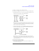
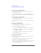
Table Of Contents
- Agilent Technologies 16750A/B Logic Analyzer
- Agilent Technologies 16750A/B Logic Analyzer
- Contents
- Getting Started
- Step 1. Connect the logic analyzer to the device under test
- Step 2. Choose the sampling mode
- Step 3. Format labels for the probed signals
- Step 4. Define the trigger condition
- Step 5. Run the measurement
- Step 6. Display the captured data
- For More Information...
- Example: Timing measurement on counter board
- Example: State measurement on counter board
- Task Guide
- Probing the Device Under Test
- Choosing the Sampling Mode
- To select transitional timing or store qualified
- Formatting Labels for Logic Analyzer Probes
- Setting Up Triggers and Running Measurements
- Displaying Captured Data
- Using Symbols
- Printing/Exporting Captured Data
- Cross-Triggering
- Solving Logic Analysis Problems
- Saving and Loading Logic Analyzer Configurations
- Reference
- The Sampling Tab
- The Format Tab
- Importing Netlist and ASCII Files
- The Trigger Tab
- The Symbols Tab
- Error Messages
- Must assign Pod 1 on the master card to specify actions for flags
- Branch expression is too complex
- Cannot specify range on label with clock bits that span pod pairs
- Counter value checked as an event, but no increment action specified
- Goto action specifies an undefined level
- Maximum of 32 Channels Per Label
- Hardware Initialization Failed
- Must assign another pod pair to specify actions for flags
- No more Edge/Glitch resources available for this pod pair
- No more Pattern resources available for this pod pair
- No Trigger action found in the trace specification
- Slow or Missing Clock
- Timer value checked as an event, but no start action specified
- Trigger function initialization failure
- Trigger inhibited during timing prestore
- Trigger Specification is too complex
- Waiting for Trigger
- Analyzer armed from another module contains no "Arm in from IMB" event
- Specifications and Characteristics
- Concepts
- Understanding Logic Analyzer Triggering
- Understanding State Mode Sampling Positions
- Getting Started
- Glossary
- Index

43
Chapter 2: Task Guide
To select transitional timing or store qualified
Selecting the State Mode (Synchronous
Sampling)
In state mode, the logic analyzer samples synchronously, based on a
sampling clock signal (or signals) from the device under test. Typically,
the signal used for sampling in state mode is a state machine or
microprocessor clock signal.
• “To select the state mode” on page 44
• “To select the 200 MHz/400 MHz state speed configuration” on page 44
• “To change the sampling clock mode” on page 44
• “To set up the sampling clock” on page 46
State Mode Sampling
Position
In order for a state mode logic analyzer to accurately capture data from
a device under test, the logic analyzer's setup/hold time (window) must
fit within the device under test's data valid window.
Because the location of the data valid window relative to the bus clock
is different for different types of buses, the logic analyzer lets you
adjust the sampling position in order to accurately capture data on
high-speed buses (see “Understanding State Mode Sampling Positions”
on page 208).
When the device under test's data valid window is less than 2.5 ns
(roughly, for clock speeds >= 200 MHz), it's easiest to use eye finder
to locate the stable and transitioning regions of signals and to
automatically adjust sampling positions.
• “To automatically adjust sampling positions” on page 47
When the device under test's data valid window is greater than 2.5 ns
(roughly, for clock speeds < 200 MHz), it's easiest to adjust the
sampling position manually, without using the logic analyzer to locate
the stable and transitioning regions of signals.
• “To manually adjust sampling positions” on page 50