
User's Manual

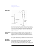

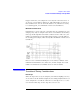
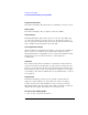
Table Of Contents
- Agilent Technologies 16750A/B Logic Analyzer
- Agilent Technologies 16750A/B Logic Analyzer
- Contents
- Getting Started
- Step 1. Connect the logic analyzer to the device under test
- Step 2. Choose the sampling mode
- Step 3. Format labels for the probed signals
- Step 4. Define the trigger condition
- Step 5. Run the measurement
- Step 6. Display the captured data
- For More Information...
- Example: Timing measurement on counter board
- Example: State measurement on counter board
- Task Guide
- Probing the Device Under Test
- Choosing the Sampling Mode
- To select transitional timing or store qualified
- Formatting Labels for Logic Analyzer Probes
- Setting Up Triggers and Running Measurements
- Displaying Captured Data
- Using Symbols
- Printing/Exporting Captured Data
- Cross-Triggering
- Solving Logic Analysis Problems
- Saving and Loading Logic Analyzer Configurations
- Reference
- The Sampling Tab
- The Format Tab
- Importing Netlist and ASCII Files
- The Trigger Tab
- The Symbols Tab
- Error Messages
- Must assign Pod 1 on the master card to specify actions for flags
- Branch expression is too complex
- Cannot specify range on label with clock bits that span pod pairs
- Counter value checked as an event, but no increment action specified
- Goto action specifies an undefined level
- Maximum of 32 Channels Per Label
- Hardware Initialization Failed
- Must assign another pod pair to specify actions for flags
- No more Edge/Glitch resources available for this pod pair
- No more Pattern resources available for this pod pair
- No Trigger action found in the trace specification
- Slow or Missing Clock
- Timer value checked as an event, but no start action specified
- Trigger function initialization failure
- Trigger inhibited during timing prestore
- Trigger Specification is too complex
- Waiting for Trigger
- Analyzer armed from another module contains no "Arm in from IMB" event
- Specifications and Characteristics
- Concepts
- Understanding Logic Analyzer Triggering
- Understanding State Mode Sampling Positions
- Getting Started
- Glossary
- Index
33
Chapter 2: Task Guide
Probing the Device Under Test
Probing the Device Under Test
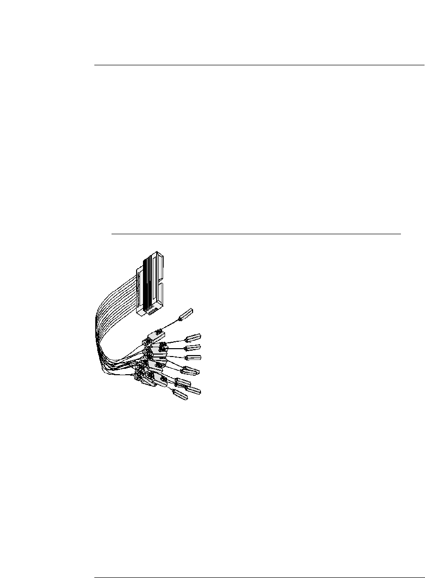
The figures below shows a variety of simple probing connections. The
specific probe type, number of probes, and location on the device
under test circuit depends on your particular measurement.
For equivalent circuit diagrams and pinouts, see the description of the
probe type in the Logic Analysis System and Measurement Modules
Installation Guide. If you have misplaced the Logic Analysis System
and Measurement Modules Installation Guide, you can download
the latest version from the world-wide web at:
http://www.cos.agilent.com/manuals/logic_analyzers.html#la_16700b
Probe Lead-to-Board
Connection
The standard lead set plugs directly into any .1-inch grid with 0.026 to
0.033-inch diameter round pins or 0.025-inch square pins. All probe
tips work with the Agilent Technologies 5059-4356 surface mount
grabbers and the Agilent Technologies 5959-0288 through-hole
grabbers.