
User's Manual
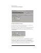
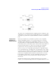

Table Of Contents
- Agilent Technologies 16750A/B Logic Analyzer
- Agilent Technologies 16750A/B Logic Analyzer
- Contents
- Getting Started
- Step 1. Connect the logic analyzer to the device under test
- Step 2. Choose the sampling mode
- Step 3. Format labels for the probed signals
- Step 4. Define the trigger condition
- Step 5. Run the measurement
- Step 6. Display the captured data
- For More Information...
- Example: Timing measurement on counter board
- Example: State measurement on counter board
- Task Guide
- Probing the Device Under Test
- Choosing the Sampling Mode
- To select transitional timing or store qualified
- Formatting Labels for Logic Analyzer Probes
- Setting Up Triggers and Running Measurements
- Displaying Captured Data
- Using Symbols
- Printing/Exporting Captured Data
- Cross-Triggering
- Solving Logic Analysis Problems
- Saving and Loading Logic Analyzer Configurations
- Reference
- The Sampling Tab
- The Format Tab
- Importing Netlist and ASCII Files
- The Trigger Tab
- The Symbols Tab
- Error Messages
- Must assign Pod 1 on the master card to specify actions for flags
- Branch expression is too complex
- Cannot specify range on label with clock bits that span pod pairs
- Counter value checked as an event, but no increment action specified
- Goto action specifies an undefined level
- Maximum of 32 Channels Per Label
- Hardware Initialization Failed
- Must assign another pod pair to specify actions for flags
- No more Edge/Glitch resources available for this pod pair
- No more Pattern resources available for this pod pair
- No Trigger action found in the trace specification
- Slow or Missing Clock
- Timer value checked as an event, but no start action specified
- Trigger function initialization failure
- Trigger inhibited during timing prestore
- Trigger Specification is too complex
- Waiting for Trigger
- Analyzer armed from another module contains no "Arm in from IMB" event
- Specifications and Characteristics
- Concepts
- Understanding Logic Analyzer Triggering
- Understanding State Mode Sampling Positions
- Getting Started
- Glossary
- Index
209
Chapter 4: Concepts
Understanding State Mode Sampling Positions
To position the setup/hold window (sampling position) within the data
valid window, a logic analyzer has an adjustable delay on each sampling
clock input (to position the setup/hold window for all the channels in a
pod).
Sample Position
Adjustments on
Individual Channels
Some logic analyzers let you adjust the position of the setup/hold
window (sampling position) on each channel. When you can make
sampling position adjustments on individual channels, you can make
the logic analyzer's setup/hold window smaller because you can correct
for the delay effects caused by the probe cables and the logic analyzer's
internal circuit board traces, and you are left with the setup/hold
requirements of the logic analyzer's internal sampling circuitry.
However, the process of manually positioning the setup/hold window
for each channel is time consuming. For each signal in the device under
test and each logic analyzer channel, you must measure the data valid
window in relation to the bus clock (with an oscilloscope), repeatedly
position the setup/hold window and run measurements to see if the
logic analyzer captures data correctly, and finally position the setup/
hold window in between the positions where data was captured
incorrectly.
In Agilent Technologies logic analyzers which have the eye finder
feature, you can automatically position the setup/hold window on each