
User's Manual
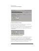

Table Of Contents
- Agilent Technologies 16750A/B Logic Analyzer
- Agilent Technologies 16750A/B Logic Analyzer
- Contents
- Getting Started
- Step 1. Connect the logic analyzer to the device under test
- Step 2. Choose the sampling mode
- Step 3. Format labels for the probed signals
- Step 4. Define the trigger condition
- Step 5. Run the measurement
- Step 6. Display the captured data
- For More Information...
- Example: Timing measurement on counter board
- Example: State measurement on counter board
- Task Guide
- Probing the Device Under Test
- Choosing the Sampling Mode
- To select transitional timing or store qualified
- Formatting Labels for Logic Analyzer Probes
- Setting Up Triggers and Running Measurements
- Displaying Captured Data
- Using Symbols
- Printing/Exporting Captured Data
- Cross-Triggering
- Solving Logic Analysis Problems
- Saving and Loading Logic Analyzer Configurations
- Reference
- The Sampling Tab
- The Format Tab
- Importing Netlist and ASCII Files
- The Trigger Tab
- The Symbols Tab
- Error Messages
- Must assign Pod 1 on the master card to specify actions for flags
- Branch expression is too complex
- Cannot specify range on label with clock bits that span pod pairs
- Counter value checked as an event, but no increment action specified
- Goto action specifies an undefined level
- Maximum of 32 Channels Per Label
- Hardware Initialization Failed
- Must assign another pod pair to specify actions for flags
- No more Edge/Glitch resources available for this pod pair
- No more Pattern resources available for this pod pair
- No Trigger action found in the trace specification
- Slow or Missing Clock
- Timer value checked as an event, but no start action specified
- Trigger function initialization failure
- Trigger inhibited during timing prestore
- Trigger Specification is too complex
- Waiting for Trigger
- Analyzer armed from another module contains no "Arm in from IMB" event
- Specifications and Characteristics
- Concepts
- Understanding Logic Analyzer Triggering
- Understanding State Mode Sampling Positions
- Getting Started
- Glossary
- Index
208
Chapter 4: Concepts
Understanding State Mode Sampling Positions
Understanding State Mode Sampling Positions
Synchronous sampling (state mode) logic analyzers are like edge-
triggered flip-flops in that they require input logic signals to be stable
for a period of time before the clock event (setup time) and after the
clock event (hold time) in order to properly interpret the logic level.
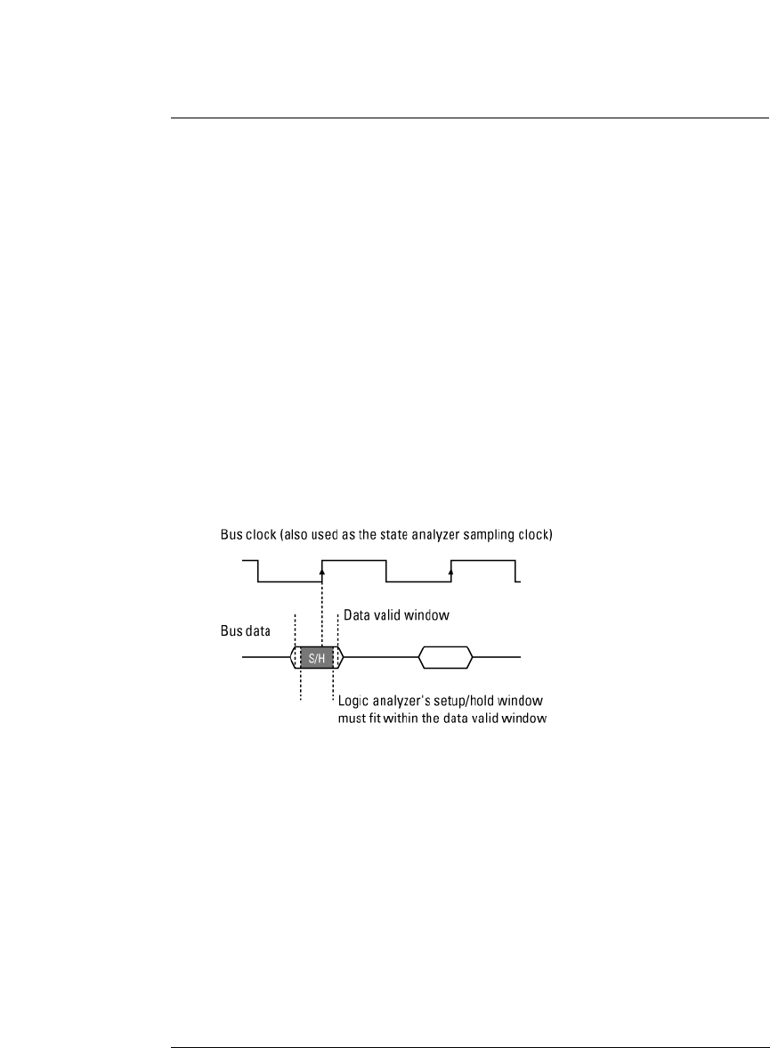
The combined setup and hold time is known as the setup/hold window.
A device under test (because of its own setup/hold requirements)
specifies that data be valid on a bus for a certain length of time. This is
known as the data valid window. The data valid window on most buses
is generally less than half of the bus clock period.
To accurately capture data on a bus:
• The logic analyzer's setup/hold time must fit within the data valid window.
• Because the location of the data valid window relative to the bus clock is
different for different types of buses, the position of the logic analyzer's
setup/hold window must be adjustable (relative to the sampling clock, and
with fine resolution) within the data valid window. For example: