
User's Manual

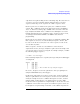
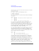


Table Of Contents
- Agilent Technologies 16750A/B Logic Analyzer
- Agilent Technologies 16750A/B Logic Analyzer
- Contents
- Getting Started
- Step 1. Connect the logic analyzer to the device under test
- Step 2. Choose the sampling mode
- Step 3. Format labels for the probed signals
- Step 4. Define the trigger condition
- Step 5. Run the measurement
- Step 6. Display the captured data
- For More Information...
- Example: Timing measurement on counter board
- Example: State measurement on counter board
- Task Guide
- Probing the Device Under Test
- Choosing the Sampling Mode
- To select transitional timing or store qualified
- Formatting Labels for Logic Analyzer Probes
- Setting Up Triggers and Running Measurements
- Displaying Captured Data
- Using Symbols
- Printing/Exporting Captured Data
- Cross-Triggering
- Solving Logic Analysis Problems
- Saving and Loading Logic Analyzer Configurations
- Reference
- The Sampling Tab
- The Format Tab
- Importing Netlist and ASCII Files
- The Trigger Tab
- The Symbols Tab
- Error Messages
- Must assign Pod 1 on the master card to specify actions for flags
- Branch expression is too complex
- Cannot specify range on label with clock bits that span pod pairs
- Counter value checked as an event, but no increment action specified
- Goto action specifies an undefined level
- Maximum of 32 Channels Per Label
- Hardware Initialization Failed
- Must assign another pod pair to specify actions for flags
- No more Edge/Glitch resources available for this pod pair
- No more Pattern resources available for this pod pair
- No Trigger action found in the trace specification
- Slow or Missing Clock
- Timer value checked as an event, but no start action specified
- Trigger function initialization failure
- Trigger inhibited during timing prestore
- Trigger Specification is too complex
- Waiting for Trigger
- Analyzer armed from another module contains no "Arm in from IMB" event
- Specifications and Characteristics
- Concepts
- Understanding Logic Analyzer Triggering
- Understanding State Mode Sampling Positions
- Getting Started
- Glossary
- Index
200
Chapter 4: Concepts
Understanding Logic Analyzer Triggering
be used in place of Global Counters, if possible, because they are easier
to use and because there is a limited number of Global Counters.
Next: “Timers” on page 200
Timers
Timers are used to check the amount of time that has elapsed between
events. For example, if you want to trigger on one edge followed by
another edge that occurs within 500ns, use a timer. The most critical
point to remember in using timers is that they need to be started
before they are tested. In other words, timers do not start
automatically.
The key to setting up a timer is to identify where it should be started
and where it should be tested. Consider the example in the following
figure. The timer should be started when the rising edge on SIG1 is
detected and it should be tested when the rising edge occurs on SIG2.
An edge followed by an edge with a time limit
An example trigger sequence to set up this measurement is:
1. If there is a Rising Edge on SIG1, then
Start Timer1
Go to 2
2. If there is a Rising Edge on SIG2 AND Timer1 < 500ns then
Trigger
While the above trigger sequence seems correct, it actually has a
critical flaw. What happens if there is a rising edge on SIG1 but SIG2
doesn't occur within 500ns? The logic analyzer will never trigger,