
User's Manual


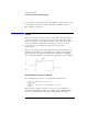
Table Of Contents
- Agilent Technologies 16750A/B Logic Analyzer
- Agilent Technologies 16750A/B Logic Analyzer
- Contents
- Getting Started
- Step 1. Connect the logic analyzer to the device under test
- Step 2. Choose the sampling mode
- Step 3. Format labels for the probed signals
- Step 4. Define the trigger condition
- Step 5. Run the measurement
- Step 6. Display the captured data
- For More Information...
- Example: Timing measurement on counter board
- Example: State measurement on counter board
- Task Guide
- Probing the Device Under Test
- Choosing the Sampling Mode
- To select transitional timing or store qualified
- Formatting Labels for Logic Analyzer Probes
- Setting Up Triggers and Running Measurements
- Displaying Captured Data
- Using Symbols
- Printing/Exporting Captured Data
- Cross-Triggering
- Solving Logic Analysis Problems
- Saving and Loading Logic Analyzer Configurations
- Reference
- The Sampling Tab
- The Format Tab
- Importing Netlist and ASCII Files
- The Trigger Tab
- The Symbols Tab
- Error Messages
- Must assign Pod 1 on the master card to specify actions for flags
- Branch expression is too complex
- Cannot specify range on label with clock bits that span pod pairs
- Counter value checked as an event, but no increment action specified
- Goto action specifies an undefined level
- Maximum of 32 Channels Per Label
- Hardware Initialization Failed
- Must assign another pod pair to specify actions for flags
- No more Edge/Glitch resources available for this pod pair
- No more Pattern resources available for this pod pair
- No Trigger action found in the trace specification
- Slow or Missing Clock
- Timer value checked as an event, but no start action specified
- Trigger function initialization failure
- Trigger inhibited during timing prestore
- Trigger Specification is too complex
- Waiting for Trigger
- Analyzer armed from another module contains no "Arm in from IMB" event
- Specifications and Characteristics
- Concepts
- Understanding Logic Analyzer Triggering
- Understanding State Mode Sampling Positions
- Getting Started
- Glossary
- Index
198
Chapter 4: Concepts
Understanding Logic Analyzer Triggering
Branches
Branches are similar to the Switch statement in the C programming
language and the Select Case statement in Basic. They provide a
method for testing multiple conditions. Each branch has its own
actions. An example of multiple branches is shown below:
1. If ADDR < 1000 then Go To 2 <- This is a branch of Level 1
Else If ADDR > 2000 then Go To 3 <- This is a 2nd branch of Level 1
Else If DATA = 2000 then Trigger <- This is a 3rd branch of Level 1
2. If DATA <= 7000 then Trigger
3. If there is a Rising Edge on SIG1, then Trigger
In sequence level 1, there are three branches, so there are three
possible actions that can be taken.
When the condition of one branch is met, none of the branches below it
are tested. In other words, there is no way for more than one branch to
be executed based upon a single sample, even if the sample causes the
conditions for more than one branch to be met. In other words, each
branch is an “Else If”.
Next: “Edges” on page 198
Edges
Edges represent a transition from low to high or high to low on a single
signal. Typically, edges are specified as “rising edge”, “falling edge”, or
“either edge”, where “rising edge” indicates a transition from a low to a
high. On most logic analyzers, up to two edges can be included in the
trigger sequence although some allow only one.
Next: “Ranges” on page 198
Ranges
Ranges are a convenient method for specifying a range of values, such
as “ADDR in range 1000 to 2000”. Most logic analyzers also support a