
User's Manual

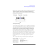
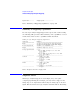
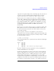
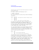


Table Of Contents
- Agilent Technologies 16750A/B Logic Analyzer
- Agilent Technologies 16750A/B Logic Analyzer
- Contents
- Getting Started
- Step 1. Connect the logic analyzer to the device under test
- Step 2. Choose the sampling mode
- Step 3. Format labels for the probed signals
- Step 4. Define the trigger condition
- Step 5. Run the measurement
- Step 6. Display the captured data
- For More Information...
- Example: Timing measurement on counter board
- Example: State measurement on counter board
- Task Guide
- Probing the Device Under Test
- Choosing the Sampling Mode
- To select transitional timing or store qualified
- Formatting Labels for Logic Analyzer Probes
- Setting Up Triggers and Running Measurements
- Displaying Captured Data
- Using Symbols
- Printing/Exporting Captured Data
- Cross-Triggering
- Solving Logic Analysis Problems
- Saving and Loading Logic Analyzer Configurations
- Reference
- The Sampling Tab
- The Format Tab
- Importing Netlist and ASCII Files
- The Trigger Tab
- The Symbols Tab
- Error Messages
- Must assign Pod 1 on the master card to specify actions for flags
- Branch expression is too complex
- Cannot specify range on label with clock bits that span pod pairs
- Counter value checked as an event, but no increment action specified
- Goto action specifies an undefined level
- Maximum of 32 Channels Per Label
- Hardware Initialization Failed
- Must assign another pod pair to specify actions for flags
- No more Edge/Glitch resources available for this pod pair
- No more Pattern resources available for this pod pair
- No Trigger action found in the trace specification
- Slow or Missing Clock
- Timer value checked as an event, but no start action specified
- Trigger function initialization failure
- Trigger inhibited during timing prestore
- Trigger Specification is too complex
- Waiting for Trigger
- Analyzer armed from another module contains no "Arm in from IMB" event
- Specifications and Characteristics
- Concepts
- Understanding Logic Analyzer Triggering
- Understanding State Mode Sampling Positions
- Getting Started
- Glossary
- Index
193
Chapter 4: Concepts
Understanding Logic Analyzer Triggering
placed on the conveyor belt, and at the other end the boxes fall off. In
other words, because logic analyzer memory is limited in depth
(number of samples), whenever a new sample is acquired the oldest
sample currently in memory is thrown away if the memory is full. This
is shown in the following figure.
The conveyor belt analogy
A logic analyzer trigger is similar to someone standing at the beginning
of the conveyor belt placing more boxes on it. They are told to “look for
a special box and to stop the conveyor belt when that box reaches a
particular position on the belt”. Using this analogy, the special box is
the trigger. Once a logic analyzer detects a sample that matches the
trigger condition, this is the indication that it should stop acquiring
more samples when the trigger is located appropriately in memory.
The location of the trigger in memory is known as the trigger position.
Normally, the trigger position is set to the middle so that the maximum
number of samples that occurred before and after the trigger are in
memory. However, you can set the trigger position to any point in
memory.
The concepts in this analogy are summed up in the following table.
Mapping of concepts in the Conveyor Belt Analogy
to a Logic Analyzer
Conveyor Belt Analogy Logic analyzer
===================== ==============================
Boxes on the belt Samples acquired from the
device under test
--------------------- ------------------------------
Number of boxes that Memory depth
will fit on the belt
--------------------- ------------------------------