
User's Manual


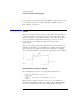
Table Of Contents
- Agilent Technologies 16750A/B Logic Analyzer
- Agilent Technologies 16750A/B Logic Analyzer
- Contents
- Getting Started
- Step 1. Connect the logic analyzer to the device under test
- Step 2. Choose the sampling mode
- Step 3. Format labels for the probed signals
- Step 4. Define the trigger condition
- Step 5. Run the measurement
- Step 6. Display the captured data
- For More Information...
- Example: Timing measurement on counter board
- Example: State measurement on counter board
- Task Guide
- Probing the Device Under Test
- Choosing the Sampling Mode
- To select transitional timing or store qualified
- Formatting Labels for Logic Analyzer Probes
- Setting Up Triggers and Running Measurements
- Displaying Captured Data
- Using Symbols
- Printing/Exporting Captured Data
- Cross-Triggering
- Solving Logic Analysis Problems
- Saving and Loading Logic Analyzer Configurations
- Reference
- The Sampling Tab
- The Format Tab
- Importing Netlist and ASCII Files
- The Trigger Tab
- The Symbols Tab
- Error Messages
- Must assign Pod 1 on the master card to specify actions for flags
- Branch expression is too complex
- Cannot specify range on label with clock bits that span pod pairs
- Counter value checked as an event, but no increment action specified
- Goto action specifies an undefined level
- Maximum of 32 Channels Per Label
- Hardware Initialization Failed
- Must assign another pod pair to specify actions for flags
- No more Edge/Glitch resources available for this pod pair
- No more Pattern resources available for this pod pair
- No Trigger action found in the trace specification
- Slow or Missing Clock
- Timer value checked as an event, but no start action specified
- Trigger function initialization failure
- Trigger inhibited during timing prestore
- Trigger Specification is too complex
- Waiting for Trigger
- Analyzer armed from another module contains no "Arm in from IMB" event
- Specifications and Characteristics
- Concepts
- Understanding Logic Analyzer Triggering
- Understanding State Mode Sampling Positions
- Getting Started
- Glossary
- Index

192
Chapter 4: Concepts
Understanding Logic Analyzer Triggering
Understanding Logic Analyzer Triggering
Setting up logic analyzer triggers can be difficult and time-consuming.
You could assume that if you know how to program, you should be able
to set up a logic analyzer trigger with no difficulty. However, this is not
true because there are many concepts that are unique to logic analysis.
The purpose of this section is to describe these key concepts and how
to use them effectively.
• “The Conveyor Belt Analogy” on page 192
• “Summary of Triggering Capabilities” on page 194
• “Sequence Levels” on page 194
• “Boolean Expressions” on page 197
• “Branches” on page 198
• “Edges” on page 198
• “Ranges” on page 198
• “Flags” on page 199
• “Occurrence Counters and Global Counters” on page 199
• “Timers” on page 200
• “Storage Qualification” on page 201
• “Strategies for Setting Up Triggers” on page 203
• “Conclusions” on page 207
See Also “Setting Up Triggers and Running Measurements” on page 64
The Conveyor Belt Analogy
The memory of a logic analyzer can be compared to a very long
conveyor belt, and the samples acquired from the Device Under Test
(DUT) as boxes on the conveyor belt. At one end, new boxes are