
User's Manual
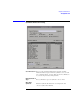

Table Of Contents
- Agilent Technologies 16750A/B Logic Analyzer
- Agilent Technologies 16750A/B Logic Analyzer
- Contents
- Getting Started
- Step 1. Connect the logic analyzer to the device under test
- Step 2. Choose the sampling mode
- Step 3. Format labels for the probed signals
- Step 4. Define the trigger condition
- Step 5. Run the measurement
- Step 6. Display the captured data
- For More Information...
- Example: Timing measurement on counter board
- Example: State measurement on counter board
- Task Guide
- Probing the Device Under Test
- Choosing the Sampling Mode
- To select transitional timing or store qualified
- Formatting Labels for Logic Analyzer Probes
- Setting Up Triggers and Running Measurements
- Displaying Captured Data
- Using Symbols
- Printing/Exporting Captured Data
- Cross-Triggering
- Solving Logic Analysis Problems
- Saving and Loading Logic Analyzer Configurations
- Reference
- The Sampling Tab
- The Format Tab
- Importing Netlist and ASCII Files
- The Trigger Tab
- The Symbols Tab
- Error Messages
- Must assign Pod 1 on the master card to specify actions for flags
- Branch expression is too complex
- Cannot specify range on label with clock bits that span pod pairs
- Counter value checked as an event, but no increment action specified
- Goto action specifies an undefined level
- Maximum of 32 Channels Per Label
- Hardware Initialization Failed
- Must assign another pod pair to specify actions for flags
- No more Edge/Glitch resources available for this pod pair
- No more Pattern resources available for this pod pair
- No Trigger action found in the trace specification
- Slow or Missing Clock
- Timer value checked as an event, but no start action specified
- Trigger function initialization failure
- Trigger inhibited during timing prestore
- Trigger Specification is too complex
- Waiting for Trigger
- Analyzer armed from another module contains no "Arm in from IMB" event
- Specifications and Characteristics
- Concepts
- Understanding Logic Analyzer Triggering
- Understanding State Mode Sampling Positions
- Getting Started
- Glossary
- Index

162
Chapter 3: Reference
The Symbols Tab
Offset By Lets you add an offset value to the starting point of a
symbol. This can be useful when compensating for
microprocessor prefetches (see “Offset By Option” on
page 162).
Align to Lets you mask the lower order bits of a symbol's value. This
can be useful for triggering on odd byte boundaries (see
“Align to x Byte Option” on page 163).
Beginning/End/
Range When a symbol represents a range of addresses, you can
choose the beginning address of the range, the end address
of the range, or the whole range.
See Also “To enter symbolic label values” on page 99
Search Pattern
Use this field to locate particular symbols in the symbol databases. To
use this field, enter the name of a file or symbol. The system searches
the symbol database for symbols that match this name. Symbols that
match appear in the list of Matching Symbols. You can also use
wildcard characters to find symbols.
Asterisk wildcard (*)
The asterisk wildcard represents "any characters." When you perform a
search on the symbol database using just the asterisk, you will see a list
of all symbols contained in the database. The asterisk can also be
added to a search word to find all symbols that begin or end with the
same letters. For example, to find all of the symbols that begin with the
letters "st", select the Search Pattern field and enter "st*".
Offset By Option
The Offset By option allows you to add an offset value to the starting
point of the symbol that you want to use. You might do this in order to
trigger on a point in a function that is beyond the preamble of the
function, or to trigger on a point that is past the prefetch depth of the
processor. Setting an offset helps to avoid false triggers in these
situations. The offset specified in the Offset By field is applied before
the address masking is done by the "Align to x Byte" option.
Example
An 80386 processor has a prefetch depth of 16 bytes. Assume functions