
User's Manual
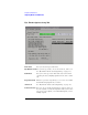
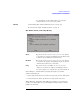
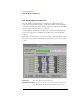

Table Of Contents
- Agilent Technologies 16750A/B Logic Analyzer
- Agilent Technologies 16750A/B Logic Analyzer
- Contents
- Getting Started
- Step 1. Connect the logic analyzer to the device under test
- Step 2. Choose the sampling mode
- Step 3. Format labels for the probed signals
- Step 4. Define the trigger condition
- Step 5. Run the measurement
- Step 6. Display the captured data
- For More Information...
- Example: Timing measurement on counter board
- Example: State measurement on counter board
- Task Guide
- Probing the Device Under Test
- Choosing the Sampling Mode
- To select transitional timing or store qualified
- Formatting Labels for Logic Analyzer Probes
- Setting Up Triggers and Running Measurements
- Displaying Captured Data
- Using Symbols
- Printing/Exporting Captured Data
- Cross-Triggering
- Solving Logic Analysis Problems
- Saving and Loading Logic Analyzer Configurations
- Reference
- The Sampling Tab
- The Format Tab
- Importing Netlist and ASCII Files
- The Trigger Tab
- The Symbols Tab
- Error Messages
- Must assign Pod 1 on the master card to specify actions for flags
- Branch expression is too complex
- Cannot specify range on label with clock bits that span pod pairs
- Counter value checked as an event, but no increment action specified
- Goto action specifies an undefined level
- Maximum of 32 Channels Per Label
- Hardware Initialization Failed
- Must assign another pod pair to specify actions for flags
- No more Edge/Glitch resources available for this pod pair
- No more Pattern resources available for this pod pair
- No Trigger action found in the trace specification
- Slow or Missing Clock
- Timer value checked as an event, but no start action specified
- Trigger function initialization failure
- Trigger inhibited during timing prestore
- Trigger Specification is too complex
- Waiting for Trigger
- Analyzer armed from another module contains no "Arm in from IMB" event
- Specifications and Characteristics
- Concepts
- Understanding Logic Analyzer Triggering
- Understanding State Mode Sampling Positions
- Getting Started
- Glossary
- Index
136
Chapter 3: Reference
Importing Netlist and ASCII Files
How the Selected Position Behaves
1. When eye finder is enabled, the selected position (blue line) is set based
on the manual setup/hold value.
2. Whenever the selected position is moved, the manual setup/hold value is
also updated. They always track each other.
3. When the manual setup/hold is enabled again, the position changes made
while eye finder was enabled can be kept or discarded.
NOTE: If eye finder changes are discarded, this includes any setup/hold settings
loaded from a configuration file while eye finder was enabled.
4. The selected position is "snapped" to the suggested position (green
triangle) each time the channel is measured.
How the Suggested Position Behaves
1. There is only a suggested position (green triangle) on channels that have
been measured.
2. The suggested position is always in the center of the stable region closest
to the selected position (blue line).
3. If the selected position is moved to a different stable region, the suggested
position "hops" to the center of that region.
4. If a stable region is open-ended, the suggested position is placed 1.25 ns
from the closed end (the visible boundary). If more than 1 clock edge is
active, the suggested position is placed 1.5 ns from the closed end.
Eye Finder Run Messages. These messages can appear in the status
area after you run a eye finder measurement.
"XX% complete"
The indicated percentage of the channels selected for the current eye
finder measurement are completed.
"Cannot run the Eye Finder at this time."
A logic analyzer measurement is currently running. Stop the logic
analyzer or wait for it to complete before running eye finder.