
User's Manual
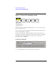
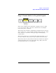
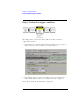
Table Of Contents
- Agilent Technologies 16750A/B Logic Analyzer
- Agilent Technologies 16750A/B Logic Analyzer
- Contents
- Getting Started
- Step 1. Connect the logic analyzer to the device under test
- Step 2. Choose the sampling mode
- Step 3. Format labels for the probed signals
- Step 4. Define the trigger condition
- Step 5. Run the measurement
- Step 6. Display the captured data
- For More Information...
- Example: Timing measurement on counter board
- Example: State measurement on counter board
- Task Guide
- Probing the Device Under Test
- Choosing the Sampling Mode
- To select transitional timing or store qualified
- Formatting Labels for Logic Analyzer Probes
- Setting Up Triggers and Running Measurements
- Displaying Captured Data
- Using Symbols
- Printing/Exporting Captured Data
- Cross-Triggering
- Solving Logic Analysis Problems
- Saving and Loading Logic Analyzer Configurations
- Reference
- The Sampling Tab
- The Format Tab
- Importing Netlist and ASCII Files
- The Trigger Tab
- The Symbols Tab
- Error Messages
- Must assign Pod 1 on the master card to specify actions for flags
- Branch expression is too complex
- Cannot specify range on label with clock bits that span pod pairs
- Counter value checked as an event, but no increment action specified
- Goto action specifies an undefined level
- Maximum of 32 Channels Per Label
- Hardware Initialization Failed
- Must assign another pod pair to specify actions for flags
- No more Edge/Glitch resources available for this pod pair
- No more Pattern resources available for this pod pair
- No Trigger action found in the trace specification
- Slow or Missing Clock
- Timer value checked as an event, but no start action specified
- Trigger function initialization failure
- Trigger inhibited during timing prestore
- Trigger Specification is too complex
- Waiting for Trigger
- Analyzer armed from another module contains no "Arm in from IMB" event
- Specifications and Characteristics
- Concepts
- Understanding Logic Analyzer Triggering
- Understanding State Mode Sampling Positions
- Getting Started
- Glossary
- Index

13
Chapter 1: Getting Started
Step 1. Connect the logic analyzer to the device under test
Step 1. Connect the logic analyzer to the device
under test
Before you begin setting up the logic analyzer for a measurement, you
need to physically connect the logic analyzer to your device under test.
There are several ways to connect logic analyzer probes to the device
under test:
• Using the general-purpose probes, the standard flying lead set, and
grabbers to connect to pins and leads in the device under test.
• By designing connectors (headers) into the device under test so that logic
analyzer probe cables and termination adapters can plug in directly.
• By designing connectors (headers) and terminations into the device under
test so that logic analyzer probe cables can plug in directly.
•Using an analysis probe to connect to microprocessors and standard
buses.
When using an analysis probe, the Setup Assistant guides you through the
connection and setup process for your particular logic analyzer and
analysis probe.
When connecting logic analyzer probes to the device under test:
1. Attach the logic analyzer probes to the device under test in a way that
keeps logically-related channels together.
2. Be sure to ground each pod.
Next: “Step 2. Choose the sampling mode” on page 14