Service Guide 3DUW 1XPEHU ( $SULO )RU :DUUDQW\ LQIRUPDWLRQ UHIHU WR WKH EDFN RI WKH PDQXDO &RS\ULJKW $JLOHQW 7HFKQRORJLHV ,QF $OO 5LJKWV 5HVHUYHG $JLOHQW ( $ '& 3RZHU 6XSSO\
The Agilent E3632A is a high performance 120 watt-dual range DC power supply with GPIB and RS-232 interfaces. The combination of bench-top and system features in this power supply provides versatile solutions for your design and test requirements.
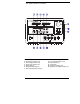
The Front Panel at a Glance 1 2 3 4 5 6 7 2 15V/7A range selection key 30V/4A range selection key Overvoltage protection key Overcurrent protection key Display limit key Recall operating state key Store operating state/Local key 8 9 10 11 12 13 Error/Calibrate key I/O Configuration/Secure key Output On/Off key Control knob Resolution selection keys Voltage/current adjust selection key
1 15V/7A range selection key Selects the 15V/7A range and allows the full rated output to 15V7A. 2 30V/4A range selection key Selects the 30V/4A range and allows the full rated output to 30V/4A. 3 Overvoltage protection key Enables or disables the overvoltage protection function, sets trip voltage level, and clears the overvoltage condition. 4 Overcurrent protection key Enables or disables the overcurrent protection function, sets trip current level, and clears the overcurrent condition.
Front-Panel Voltage and Current Limit Settings You can set the voltage and current limit values from the front panel using the following method. Use the voltage/current adjust selection key, the resolution selection keys, and the control knob to change the voltage and current limit value. 1 Select the desired range using the range selection keys after turning on the power supply. 2 Press the Display Limit key to show the limit values on the display.
Display Annunciators Adrs Rmt 15V 30V OVP OCP CAL Limit ERROR OFF Unreg CV CC Power supply is addressed to listen or talk over a remote interface. Power supply is in remote interface mode. Shows the 15V/7A range is selected. Shows the 30V/4A range is selected. The overvoltage protection function is enabled when the annunciator turns on or the overvoltage protection circuit has caused the power supply to shutdown when the annunciator blinks.
The Rear Panel at a Glance 1 Power-line voltage setting 2 Power-line fuse-holder assembly 3 AC inlet 4 Power-line module 5 GPIB (IEEE-488) interface connector 6 RS-232 interface connector Use the front-panel I/O Config key to: • Select the GPIB or RS-232 interface (see chapter 3). • Set the GPIB bus address (see chapter 3). • Set the RS-232 baud rate and parity (see chapter 3).
In This Book Specifications Chapter 1 lists the power supply’s specifications and describes how to interpret these specifications. Quick Start Chapter 2 prepares the power supply for use and helps you get familiar with the front-panel features. Calibration Procedures Chapter 3 provides performance verification and calibration procedures. Theory of Operation Chapter 4 describes block and circuit level theory related to the operation of the power supply.
8
Contents Chapter 1 Specifications Performance Specifications 15 Supplemental Characteristics 17 Chapter 2 Quick Start Contents To Prepare the Power Supply for Use 23 To Check the Rated Voltages of the Power Supply 25 To Check the Rated Currents of the Power Supply 26 To Use the Power Supply in Constant Voltage Mode 28 To Use the Power Supply in Constant Current Mode 30 To Store and Recall the Instrument State 32 To Program Overvoltage Protection 34 Setting the OVP Level and Enable the OVP Circuit 34 Che
Contents Chapter 3 Calibration Procedures (continued) Contents Constant Voltage (CV) Verifications 49 Constant Voltage Test Setup 49 Voltage Programming and Readback Accuracy 49 CV Load Regulation 50 CV Line Regulation 50 Normal Mode Voltage Noise (CV Ripple and Noise) 51 Load Transient Response Time 52 Constant Current (CC) Verifications 53 Constant Current Test Setup 53 Current Programming and Readback Accuracy 53 CC Load Regulation 54 CC Line Regulation 55 Normal Mode Current Noise (CC Ripple and Nois
Contents Chapter 5 Service Operating Checklist 91 Types of Service Available 92 Repacking for Shipment 93 Electrostatic Discharge (ESD) Precautions 94 Surface Mount Repair 94 To Replace the Power-Line Fuse 94 To Disconnect the Output Using an External Relay Troubleshooting Hints 96 Self-Test Procedures 98 95 Chapter 6 Replaceable Parts Contents Replaceable Parts 102 To Order Replaceable Parts 102 Backdating and Part Changes 102 E3632-60002 Main PC Assembly 103 E3632-60004 Front-Panel Display PC Assembl
Contents Contents 12
1 1 Specifications
Specifications The performance specifications are listed in the following pages. Specifications are warranted in the temperature range of 0 to 40°C with a resistive load. Supplemental characteristics, which are not warranted but are descriptions of performance determined either by design or testing. Chapter 3 "Calibration Procedures" contains procedures for verifying the performance specifications.
Chapter 1 Specifications Performance Specifications 1 Performance Specifications Output Ratings (@ 0°C - 40°C) Low range High range 0 to +15 V/0 to 7 A 0 to +30 V/0 to 4 A Programming Accuracy [1] 12 months (@ 25°C ± 5°C), ±(% of output + offset) Voltage Current 0.05% + 10 mV 0.2% + 10 mA Readback Accuracy [1] 12 months (over GPIB and RS-232 or front panel with respect to actual output @ 25°C ± 5°C), ±(% of output + offset) Voltage Current 0.05% + 5 mV 0.
Chapter 1 Specifications Performance Specifications Programming Resolution Voltage Current 1 mV 0.5 mA Readback Resolution Voltage Current 0.5 mV 0.
Chapter 1 Specifications Supplemental Characteristics 1 Supplemental Characteristics Output Programming Range (maximum programmable values) Low range High range OVP OCP 0 to 15.45 V/0 to 7.21 A 0 to 30.9 V/0 to 4.12 A 1 V to 32 V 0 A 7.5 A Remote Sensing Capability Voltage drop Load regulation Load voltage Up to 1 V per each lead Add 5 mV to spec for each 1-volt change in the + output lead due to load current changes. Subtract voltage drop in load leads from specified output voltage atiing.
Chapter 1 Specifications Supplemental Characteristics Output Terminal Isolation (maximum, from chassis ground) ±60 Vdc when connecting shorting conductors without insulation to the (+) output to the (+) sense and the (-) output and the (-) sense terminals. ±240 Vdc when connecting insulated shorting conductors to the (+) output to the (+) sense and the (-) output and the (-) sene terminals.
Chapter 1 Specifications Supplemental Characteristics 1 Dimensions* 213 mmW x 133 mmH x 348 mmD (8.4 x 5.2 x 13.7 in) *See below for detailed information. Weight Net Shipping 9.5 kg (21 lb) 12 kg (26 lb) Figure 1-1.
Chapter 1 Specifications Supplemental Characteristics 20
2 2 Quick Start
Quick Start One of the first things you will want to do with your power supply is to become acquainted with its front panel. Written procedures in this chapter prepare the power supply for use and familiarize you with most front-panel operations. • The power supply is shipped from the factory configured in the front-panel operation mode. At power-on, the power supply is automatically set to operate in the front-panel operation mode. When in this mode, the frontpanel keys can be used.
Chapter 2 Quick Start To Prepare the Power Supply for Use To Prepare the Power Supply for Use The following steps help you verify that the power supply is ready for use. 2 1 Check the list of supplied items. Verify that you have received the following items with your power supply. If anything is missing, contact your nearest Agilent Technologies Sales Office. One appropriate power cord for your location. One User's Guide. This Service Guide. Certificate of Calibration.
Chapter 2 Quick Start To Prepare the Power Supply for Use 1 Remove the power cord. Remove the fuse-holder assembly with a flatblade screwdriver from the rear 2 Install the corect line fuse. Remove the power-line voltage selector from the power-line module. 100 or 115 Vac, 4 AT fuse 230 Vac, 2.5 AT fuse 3 Rotate the power-line voltage selector until the correct voltage appears. 4 Replace the power-line voltage selector and the fuse-holder assembly in the rear panel.
Chapter 2 Quick Start To Check the Rated Voltages of the Power Supply To Check the Rated Voltages of the Power Supply The following procedures check to ensure that the power supply develops its rated voltage outputs with no load and properly responds to operation from the front panel. For each step, use the keys shown on the left margins. Power 1 Turn on the power supply.
Chapter 2 Quick Start To Check the Rated Currents of the Power Supply To Check the Rated Currents of the Power Supply The following procedures check to ensure that the power supply develops its rated current outputs with a short and properly responds to operation from the front panel. For each step, use the keys shown on the left margin. Power 1 Turn on the power supply.
Chapter 2 Quick Start To Check the Rated Currents of the Power Supply 6 Ensure that the current can be adjusted from zero to the maximum 1 rated value. Adjust the knob until the ammeter indicates 0 amps and then until the ammeter indicates 7.0 amps. Note If an error has been detected during the output checkout procedures, the ERROR annunciator will turn on. See "Error Messages" for more information, starting on page 121 in chapter 5 of the User's Guide.
Chapter 2 Quick Start To Use the Power Supply in Constant Voltage Mode To Use the Power Supply in Constant Voltage Mode To set up the power supply for constant voltage (CV) operation, proceed as follows. For each step, use the keys shown on the left margin. 1 Connect a load to the desired output terminals. With power-off, connect a load to the desired output terminals. Power 2 Turn on the power supply.
Chapter 2 Quick Start To Use the Power Supply in Constant Voltage Mode Volt/Curr 5 Adjust the knob for the desired output voltage. 1 Check that the Limit annunciator still blinks. Set the knob for voltage control. The second digit of the voltmeter will be blinking. Change the blinking digit using the resolution selection keys and adjust the knob to the desired output voltage. Display Limit 6 Return to the meter mode.
Chapter 2 Quick Start To Use the Power Supply in Constant Current Mode To Use the Power Supply in Constant Current Mode To set up the power supply for constant current (CC) operation, proceed as follows. For each step, use the keys shown on the left margin. 1 Connect a load to the output terminals. With power-off, connect a load to the (+) and (-) output terminals. Power 2 Turn on the power supply.
Chapter 2 Quick Start To Use the Power Supply in Constant Current Mode Volt/Curr 5 Adjust the knob for the desired output current. 1 Check that the Limit annunciator still blinks. Set the knob for current control. The second digit of the ammeter will be blinking. Change the blinking digit using the resolution selection keys and adjust adjust the knob to the desired output current. Display Limit 6 Return to the meter mode.
Chapter 2 Quick Start To Store and Recall the Instrument State To Store and Recall the Instrument State You can store up to three different operating states in non-volatile memory. This also enables you to recall the entire instrument with just a few key presses from the front panel. The memory locations are supplied with the reset state from the factory for front panel operation. Refer to the description of *RST command, starting on page 94 in the User’s Guide for more information.
Chapter 2 Quick Start To Store and Recall the Instrument State Store 4 Save the operating state. The operating state is now stored. To recall the stored state, go to the following steps. 2 done This message appears on the display for approximately 1 second. Recall 5 Turn on the recall mode. Memory location "1" will be displayed in the recall mode. recall 1 This message appears on the display for approximately 3 seconds. 6 Recall the stored operating state.
Chapter 2 Quick Start To Program Overvoltage Protection To Program Overvoltage Protection Overvoltage protection guards the load against output voltages that reach a specified value greater than the programmed protection level. It is accomplished by shorting the output via an internal SCR when the trip level is set to equal or greater than 3 volts, or by progamming the output to 1 volt when the trip level is set to less than 3 volts.
Chapter 2 Quick Start To Program Overvoltage Protection 5 Exit the OVP menu. changed The "CHANGED" message is displayed for a second to show that the new OVP trip level is now in effect. If the OVP settings are not changed, "NO CHANGE" will be displayed. The power supply will exit the OVP menu and the display will return to the meter mode. Check that the OVP annunciator turns on. Checking OVP Operation To check OVP operation, raise the output voltage to near the trip point.
Chapter 2 Quick Start To Program Overvoltage Protection Over Voltage 3 Clear the overvoltage condition and exist this menu. Now, when you press the Over Voltage key again, the "DONE" message is displayed for a second and the OVP annunciator will not blink any more. The output will return to meter mode.
Chapter 2 Quick Start To Program Overcurrent Protection To Program Overcurrent Protection Overcurrent protection guards the load against output currents that reach a specified value greater than the programmed protection level. It is accomplished by programming the output current to zero. The following steps show how to set the overcurrent protection trip level, how to check OCP operation and how to clear overcurrent condition.
Chapter 2 Quick Start To Program Overcurrent Protection The "CHANGED" message is displayed for a second to show that the new OCP trip level is now in effect. If the OCP settings are not changed, "NO CHANGE" will be displayed. The power supply will exit the OCP menu and the display will return to the meter mode. Check that the OCP annunciator turns on. Checking OCP Operation To check OCP operation, raise the output current to near the trip point.
Chapter 2 Quick Start To Rack Mount the Power Supply To Rack Mount the Power Supply The power supply can be mounted in a standard 19-inch rack cabinet using one of three optional kits available. A rack-mounting kit for a single instrument is available as Option 1CM (P/N 5063-9243). Installation instructions and hardware are included with each rack-mounting kit. Any Agilent System II instrument of the same size can be rack-mounted beside the Agilent E3632A power supply.
Chapter 2 Quick Start To Rack Mount the Power Supply To rack mount two instruments of the same depth side-by-side, order lock-link kit 5061-9694 and flange kit 5063-9214. To install two instruments in a sliding support shelf, order support shelf 50639256, and slide kit 1494-0015.
3 Calibration Procedures
Calibration Procedures This chapter contains procedures for verification of the power supply's performance and calibration (adjustment).
Chapter 3 Calibration Procedures Agilent Technologies Calibration Services Closed-Case Electronic Calibration The power supply features closedcase electronic calibration since no internal mechanical adjustments are required for normal calibration. The power supply calculates correction factors based upon the input reference value you enter. The new correction factors are stored in non-volatile memory until the next calibration adjustment is performed.
Chapter 3 Calibration Procedures Automating Calibration Procedures Automating Calibration Procedures You can automate the complete verification procedures outlined in this chapter if you have access to programmable test equipment. You can program the instrument configurations specified for each test over the remote interface. You can then enter readback verification data into a test program and compare the results to the appropriate test limit values.
Chapter 3 Calibration Procedures Test Considerations Test Considerations To ensure proper instrument operation, verify that you have selected the correct power-line voltage prior to attempting any test procedure in this chapter. page 24 for more information. For optimum performance verification, all test procedures should comply with the following recommendations. • Assure that the calibration ambient temperature is stable and between 20°C and 30°C. • Assure ambient relative humidity is less than 80%.
Chapter 3 Calibration Procedures Performance Verification Tests Performance Verification Tests The performance verification tests use the power supply's specifications listed in chapter 1, "Specifications", starting on page 13. You can perform two different levels of performance verification tests: • Self-Test A series of internal verification tests that provide high confidence that the power supply is operational.
Chapter 3 Calibration Procedures Measurement Techniques Measurement Techniques Setup for Most Tests Most tests are performed at the front terminals as shown in the following figure. Measure the dc voltage directly at the (+) and (-) terminals on the front panel. 3 Figure 3-1. Performance Verification Test Setup Electronic Load Many of the test procedures require the use of a variable load resistor capable of dissipating the required power.
Chapter 3 Calibration Procedures Measurement Techniques General Measurement Techniques To achieve best results when measuring load regulation, peak to peak voltage, and transient response time of the power supply, measuring devices must be connected through the hole in the neck of the binding post at (A) while the load resistor is plugged into the front of the output terminals at (B). A measurement made across the load includes the impedance of the leads to the load.
Chapter 3 Calibration Procedures Constant Voltage (CV) Verifications Constant Voltage (CV) Verifications Constant Voltage Test Setup If more than one meter or a meter and an oscilloscope are used, connect each to the (+) and (-) terminals by a separate pair of leads to avoid mutual coupling effects. Use coaxial cable or shielded 2-wire cable to avoid noise pick-up on the test leads.
Chapter 3 Calibration Procedures Constant Voltage (CV) Verifications 7 Program the output voltage to full rated value (30.0V) by sending the command. VOLT 30.0 8 Record the output voltage reading on the digital voltmeter (DVM). The readings should be within the limits of (30V 5mV). 9 Readback the output voltage over the remote interface by sending the command: MEAS:VOLT? 10 Record the value displayed on the controller. This value should be within the limits of (DVM 0mV).
Chapter 3 Calibration Procedures Constant Voltage (CV) Verifications 2 Connect the ac power line through a variable voltage transformer. 3 Turn on the power supply. Select the 30V/4A range, enable the output, and set the display to the limit mode. When the display is in the limit mode, program the current to the full rated value (4.0A) and the voltage to full rated value (30.0V). 4 Operate the electronic load in constant current mode and set its current to 4.0A. Check that the CV annunciator remains lit.
Chapter 3 Calibration Procedures Constant Voltage (CV) Verifications Load Transient Response Time This test measures the time for the output voltage to recover to within 15 mV of nominal output voltage following a load change from full load to half load, or half load to full load. 1 Turn off the power supply and connect the output to be tested as shown in Figure 3-1 with an oscilloscope. Operate the electronic load in constant current mode. 2 Turn on the power supply.
Chapter 3 Calibration Procedures Constant Current (CC) Verifications Constant Current (CC) Verifications Constant Current Test Setup Follow the general setup instructions in the "Measurement Techniques" section, starting on page 47 and the specific instructions will be given in the following paragraphs. Current Programming and Readback Accuracy This test verifies that the current programming and GPIB or RS-232 readback functions are within specifications.
Chapter 3 Calibration Procedures Constant Current (CC) Verifications 7 Program the output current to the full rated value (7.0A) by sending the commands: CURR 7.0 8 Divide the voltage drop (DVM reading) across the current monitoring resistor (RM) by its resistance to convert to amps and record this value (IO). This value should be within the limit of (7A 4mA). 9 Readback the output current over the remote interface by sending the command: MEAS:CURR? 10 Record the value displayed on the controller.
Chapter 3 Calibration Procedures Constant Current (CC) Verifications CC Line Regulation This test measures the change in output current that results from a change in ac line voltage from the minimum value (10% below the nominal input voltage) to the maximum value (10% above nominal voltage). 1 Turn off the power supply and connect the output to be tested as shown in Figure 3-1 with the digital voltmeter connected across the current monitoring resistor (RM).
Chapter 3 Calibration Procedures Common Mode Current Noise 2 Turn on the power supply. Select the 15V/7A range, enable the output, and set the display to the limit mode. When the display is in the limit mode, program the current to full rated value (7.0A) and the voltage to the full rated value (15.0V). 3 The output current should be at the full-rated rating with the CC annunciator on. If not lit, adjust the load so that the output voltage drops slightly until the CC annunciator lights.
Chapter 3 Calibration Procedures Performance Test Record for Agilent E3632A Performance Test Record for Agilent E3632A CV Performance Test Record Test Description Specifications Actual Result Upper Limit Lower Limit CV Programming Accuracy @ 0 volts (DVM reading) +0.0100 V -0.0100 V CV Readback Accuracy @ 0 volts DVM + 0.0050 V DVM - 0.0050 V CV Programming Accuracy @ Full Scale (DVM reading) +30.025V 29.9750 V CV Readback Accuracy @ Full Scale DVM + 0.0200 V DVM - 0.
Chapter 3 Calibration Procedures Calibration Security Code Calibration Security Code This feature allows you to enter a security code (electronic key) to prevent accidental or unauthorized calibrations of the power supply. When you first receive your power supply, it is secured. Before you can calibrate the power supply, you must unsecure it by entering the correct security code. A procedure to unsecure the power supply is given on the following page.
Chapter 3 Calibration Procedures Calibration Security Code To Unsecure the Power Supply for Calibration The power supply can use a calibration security code to prevent unauthorized or accidental calibration. This procedure shows you how to unsecure the power supply for calibration from the front panel. Calibrate 1 Turn on the front-panel calibration mode.
Chapter 3 Calibration Procedures Calibration Security Code Secure 4 Unsecure the power supply. unsecured The power supply is unsecured when you press the Secure key. You will see the above message from the front panel for one second. The "CAL MODE" message is displayed on the front panel after above message. Power 5 Turn off the calibration mode. Turn off the power supply to exit the calibration mode. To re-secure the power supply (following calibration), perform this procedure again.
Chapter 3 Calibration Procedures Calibration Count Calibration Count The calibration count feature provides an independent "serialization" of your calibrations. You can determine the number of times that your power supply has been calibrated. By monitoring the calibration count, you can determine whether an unauthorized calibration has been performed. Since the value increments by one for each calibration parameter (see Table 3-2 on the next page), a complete calibration increases the value by 5 counts.
Chapter 3 Calibration Procedures General Calibration/Adjustment Procedure General Calibration/Adjustment Procedure The calibration procedures from the front panel are described in this section. For voltage calibration, disconnect all loads from the power supply and connect a DVM across the output terminals. For current calibration, disconnect all loads from the power supply, connect an appropriate current monitoring resistor (0.
Chapter 3 Calibration Procedures General Calibration/Adjustment Procedure To calibrate the output voltages and currents of the power supply from the front panel, proceed as follows: 1 Unsecure the power supply. To calibrate the voltage and current, you must unsecure the power supply according to the procedure given on page 59. 2 Disconnect all loads from the power supply and connect a DVM across output terminals. Calibrate 3 Turn on the calibration mode.
Chapter 3 Calibration Procedures General Calibration/Adjustment Procedure v lo +0.5000 v Then, the display shows the low voltage calibration point. 6 Read the DVM and change the low voltage value on the display to match the measured voltage. For example, if the DVM reading is 0.4500 V, adjust the voltage to 0.4500 V using the knob and resolution selection keys. v lo +0.4500 v Calibrate 7 Pressing the "Calibrate" key saves the change and selects the middle voltage calibration point. v Mi +15.
Chapter 3 Calibration Procedures General Calibration/Adjustment Procedure If the entered number is within an acceptable range, a "ENTERED" message appears for one second. If the entered number is not correct, an "MIN VALUE" or "MAX VALUE" message appears for one second and the display shows the middle voltage calibration point again. The display now shows the high voltage calibration point. 10 Read the DVM and change the first voltage value on the display to match the measured voltage.
Chapter 3 Calibration Procedures General Calibration/Adjustment Procedure 12 Pressing the "Calibrate" key saves the new calibration constants for OVP circuit and goes to the current calibration mode. cal setup 3 A "CALIBRATING" message appears for about several seconds to indicate that the OVP calibration is progressing and new calibration constants of "SETUP 2" are stored. Then, the display shows the above message to indicate that the power supply is ready for the current calibration.
Chapter 3 Calibration Procedures General Calibration/Adjustment Procedure 16 Read the DVM and change the middle current value on the display to match the computer current (DVM reading ¸ by shunt resistance). For example, if the computered value is 3.499 A, adjust the current to 3.499 A using the knob and arrow keys. Notice that you should wait for the DVM reading to stabilize for accurate calibration. i mi 3.
Chapter 3 Calibration Procedures Aborting a Calibration in Progress Calibrate 19 Pressing the "Calibrate" key saves the new calibration constants for the output current and goes to the OCP calibration mode. cal setup 4 A "CALIBRATING" message appears for one second to indicate that the current calibration is progressing and new calibration constants of "SETUP 3" are stored. Then, the display shows the above message to indicate that the power supply is ready for the OCP calibration.
Chapter 3 Calibration Procedures Calibration Record for Agilent E3632A Calibration Record for Agilent E3632A Step Calibration Description Measurement Mode (DVM) Supply being Adjusted 1 Unsecure the power supply (see page 59). 2 Turn on "CAL MODE"(simultaneously press "Calibrate" and "Power" keys) until it beeps. 3 Move down menu to "CAL SETUP 1" (press "Calibrate" key).
Chapter 3 Calibration Procedures Error Messages Error Messages The following tables are abbreviated lists of error messages for the E3632A. The errors listed are the most likely errors to be encountered during calibration and adjustment. A more complete list of error messages and descriptions is contained in chapter 5 of the E3632A User's Guide.
Chapter 3 Calibration Procedures Error Messages Calibration Error Messages Error Error Message 701 702 703 704 705 708 712 713 714 715 716 717 740 741 742 743 744 745 746 747 748 749 750 Cal security disabled by jumper Cal secured Invalid secure code Secure code too long Cal aborted Cal output disabled Bad DAC cal data Bad readback cal data Bad OVP cal data Bad OCP cal data Bad OVP DNL error correction data Cal OVP or OCP status enabled Cal checksum failed, secure state Cal checksum failed, string data
Chapter 3 Calibration Procedures Calibration Program Calibration Program This section contains an Agilent BASIC program for calibration over the GPIB interface. This program makes software adjustments to the E3632A power supply using a current shunt and a digital mutimeter which is connected to the controller. In this program a 0.01 ohm current shunt is used.
Chapter 3 Calibration Procedures Calibration Program continued 370 380 390 400 410 420 430 440 450 460 470 480 490 500 510 520 530 540 550 560 570 580 590 600 610 620 630 640 650 660 670 680 690 700 710 720 730 740 750 760 770 780 790 800 810 820 830 840 850 860 870 ! ! Perform the DAC error correction, voltage calibration and OVP calibration. ! Alert the operator to hook up the connection before calibrating.
Chapter 3 Calibration Procedures Calibration Program continued 880 OUTPUT @Pwrsupply;"CAL:VOLT:DATA ";Dmm_rdg ! send stored value to Power Supply 890 OUTPUT @Pwrsupply;"CAL:VOLT:LEV MID" ! set output to middle cal value 900 WAIT 2 ! allow output to settle 910 OUTPUT @Dmm;"MEAS:VOLT:DC?" ! measure output with Dmm and 920 ENTER @Dmm;Dmm_rdg ! store in variable Dmm_rdg 930 PRINT Dmm_rdg 940 OUTPUT @Pwrsupply;"CAL:VOLT:DATA ";Dmm_rdg ! send stored value to Power Supply 950 OUTPUT @Pwrsupply;"CAL:VOLT:LEV MAX"
Chapter 3 Calibration Procedures Calibration Program continued 1380 CLEAR SCREEN 1390 PRINT TABXY(10,5),"DAC ERROR CORRECTION AND VOLTAGE/OVP CALIBRATION COMPLETE" 1400 WAIT 4 1410 ! 1420 ! Perform the Current calibration and OCP calibration. Alert the operator to 1430 ! hook up the connection before calibrating.
Chapter 3 Calibration Procedures Calibration Program continued 1860 1870 1880 1890 1900 1910 1920 1930 1940 1950 1960 1970 1980 1990 2000 2010 2020 2030 2040 2050 2060 2070 2080 2090 2100 2110 2120 2130 2140 2150 2160 2170 2180 2190 2200 2210 2220 2230 2240 2250 2260 2270 2280 2290 ! CLEAR SCREEN IF Error$="+0,""No error""" THEN PRINT "Current calibration completed for Power Supply " ELSE PRINT "ERROR:";Error$;"Current not Calibrated" BEEP GOTO 2250 END IF CLEAR SCREEN PRINT TABXY(10,5),"CURRENT CALIBRATI
4 4 Theory of Operation
Theory of Operation This chapter provides block diagram level descriptions of the power supply. The descriptions provide a basic understanding of circuit operation and are intended as an aid in troubleshooting. It is assumed in the following discussions that you are familiar with the operating and programming instructions presented in the E3632A User's Guide.
Chapter 4 Theory of Operation Block Diagram Overview Block Diagram Overview This discussion pertains to the block diagram on the next page. The power supply's circuitry is divided into two major blocks: the floating circuitry and the ground referenced circuitry. All power mesh and control circuits, display circuit, and digital circuits are contained in the floating circuitry. This circuitry also contains the power supply's main controller.
Chapter 4 Theory of Operation Block Diagram Overview Block Diagram 80
Chapter 4 Theory of Operation AC Input and Bias Supplies AC Input and Bias Supplies Referring to the schematic shown on page 121 and 122, the ac mains are connected by a fused power module. This module incorporates the functions of mains connection, fusing, and line voltage selection (100/115/230 Vac). The line voltage selection function of the module selects which primary winding of power transformer is energized. The transformer secondary windings are connected to the main pc board through connectors.
Chapter 4 Theory of Operation Floating Logic Floating Logic Referring to the schematic shown on page 124, the floating common logic controls operation of the entire instrument. All output functions and bus command interpretation is performed in the main controller U17. The front panel and the earth referenced logic operate as slaves to U17.
Chapter 4 Theory of Operation Floating Logic The serial register is used to send and receive serial data bytes from the main controller to the DAC system, or to communicate with the front panel controller. The serial register is multiplexed to these two circuits. The transmission rate is selected to 1.5 M bits/second for the DAC system and 93.75 k bits/second for communication with the front panel controller. The general serial interface is a 3-bit interface as shown below.
Chapter 4 Theory of Operation D-to-A Converter D-to-A Converter Referring to the schematic shown on page 123, all reference voltages of power circuits are derived from the internal voltage reference of system DAC U21. The system DAC track/hold amplifier outputs are used to provide controllable reference voltages to three power circuits. The system DAC is programmed and responds to the main controller via internal 3-wire serial data bus SERCLK, SERRBK, and SERSTB.
Chapter 4 Theory of Operation A-to-D Converter A-to-D Converter Referring to the schematic shown on page 123, the analog-to-digital converter (ADC) is used to change dc voltages into digital information. The circuitry consists of an integrator amplifier (U26 and U29), current steering switch U33, resistors (R70, R71, and R96), voltage reference U32, ADC controller U18, and residue ADC U17. The ADC method used by the Agilent E3632A is called multislope III.
Chapter 4 Theory of Operation Power Mesh and Control Power Mesh and Control Refer to the schematics shown on page 121. For the power mesh and control circuit, a preregulator is added ahead of the series pass transistor to minimize the power dissipated in the series pass transistor by controlling the dc level across the input filter capacitor, depending on the output voltage.
Chapter 4 Theory of Operation Power Mesh and Control Two error amplifiers are included in a CV/CC supply, one for controlling output voltage, the other for controlling output current.
Chapter 4 Theory of Operation Earth-Referenced Logic Earth-Referenced Logic Referring to the schematic shown on page 125, the earth referenced logic circuits schematic provides all rear panel input/output capability. Microprocessor U4 handles GPIB (IEEE-488) control through bus interface chip U3 and bus receiver/driver chips U1 and U2. The RS-232 interface is also controlled through microprocessor U4.
5 5 Service
Service This chapter discusses the procedures involved for returning a failed power supply to Agilent Technologies for service or repair.
Chapter 5 Service Operating Checklist Operating Checklist Before returning your power supply to Agilent Technologies for service or repair check the following items: Is the Power Supply Inoperative? Verify that the ac power cord is connected to the power supply. Verify that the front-panel power switch is depressed. Verify that the power-line fuse is installed: Use the 4 AT, 250 V fuse for 100 or 115 Vac operation. Use the 2.5 AT, 250 V fuse for 230 Vac operation. Verify the power-line voltage setting.
Chapter 5 Service Types of Service Available Types of Service Available If your power supply fails within three years of original purchase, Agilent Technologies will repair or replace it free of charge. If your unit fails after your three year warranty expires, Agilent will repair or replace it as a very competitive price. Agilent will make the decision locally whether to repair or replace your unit. Standard Repair Service (worldwide) Contact your nearest Agilent Technologies Service Center.
Chapter 5 Service Repacking for Shipment • If your failed unit was "in-warranty,'' your replacement unit continues the original three year warranty period. You will not be billed for the replacement unit as long as the failed unit is received by Agilent. • If your three year warranty has expired, Agilent Technologies will bill you for the Agilent E3632A exchange price - less than a new unit price. Agilent warrants exchange units against defects for 90 days.
Chapter 5 Service Electrostatic Discharge (ESD) Precautions Electrostatic Discharge (ESD) Precautions Almost all electrical components can be damaged by electrostatic discharge (ESD) during handling. Component damage can occur at electrostatic discharge voltages as low as 50 volts. The following guidelines will help prevent ESD damage when serving the power supply or any electronic device. • • • • • • Disassemble instruments only in a static-free work area.
Chapter 5 Service To Disconnect the Output Using an External Relay To Disconnect the Output Using an External Relay When the output of the E3632A is turned off, it is implemented by setting the output to 0 volts and 0.02 amps. This gives a zero output voltage without actually disconnecting the output. To disconnect the output, an external relay must be connected between the output and the load. A TTL signal of either low true or high true is provided to control an external relay.
Chapter 5 Service Troubleshooting Hints Troubleshooting Hints This section provides a brief check list of common failures. Before troubleshooting or repairing the power supply, make sure that the failure is in the instrument rather than any external connections. Also make sure that the instrument is accurately calibrated. The power supply's circuits allow troubleshooting and repair with basic equipment such as a digit multimeter and a 100 MHz oscilloscope.
Chapter 5 Service Troubleshooting Hints Bias Supplies Problems Check that the input to the voltage regulators of the bias supplies is at least 1 V greater than their output. Circuit failures can cause heavy loads of the bias supplies which may pull down the regulator output voltages. Check the voltages of bias supplies as tabulated below. Table 5-1. Bias Supplies Voltages Bias Supply +5V Floating -5.1V Floating +15V Floating -15V Floating Minimum Maximum +4.75 V -4.75 V +14.25 V -14.25 V +5.25 V -5.
Chapter 5 Service Self-Test Procedures Self-Test Procedures Power-On Self-Test Each time the power supply is powered on, a set of self-tests are performed. These tests check that the minimum set of logic and measurement hardware are functioning properly. The power-on self-test performs checks 601 through 604 and 624 through 634. Complete Self-Test Hold any front panel key except the "Error'' key for more than 5 seconds while turning on the power to perform a complete self-test.
Chapter 5 Service Self-Test Procedures 606 Rundown gain out of range This test checks the nominal gain between the integrating ADC and the U17 on-chip ADC. The nominal gain is checked to ±10% tolerance. 607 Rundown too noisy This test checks the gain repeatability between the integrating ADC and the U17 on-chip ADC. The gain test (606) is performed eight times. Gain noise must be less that ±64 lsb's of the U17 on-chip ADC.
Chapter 5 Service Self-Test Procedures 100
6 6 Replaceable Parts
Replaceable Parts 7KLV FKDSWHU FRQWDLQV LQIRUPDWLRQ RUGHULQJ UHSODFHPHQW SDUWV IRU \RXU SRZHU VXSSO\ 7KH SDUWV OLVWV DUH GLYLGHG LQWR WKH IROORZLQJ IRXU JURXSV ( 0DLQ 3& $VVHPEO\ SDJH ( )URQW 3DQHO 'LVSOD\ 3& $VVHPEO\ SDJH ( )URQW )UDPH $VVHPEO\ SDJH $JLOHQW ( $ 3RZHU 6XSSO\ $VVHPEO\ SDJH 3DUWV DUH OLVWHG LQ WKH DOSKDQXPHULF RUGHU DFFRUGLQJ WR WKHLU VFKHPDWLF UHIHUHQFH GHVLJQDWRUV 7KH SDUW OLVWV LQFOXGH D EULHI GHVFULSWLRQ RI WKH SDUW ZLWK
Chapter 6 Replaceable Parts E3632-60002 Main PC Assembly E3632-60002 Main PC Assembly Reference Designator Agilent Part Number Qty Part Description Mfr. Code C1 0180-4228 C2-6 0160-6497 C7-8 0160-6225 2 C9-12 0160-6497 1 CAP-FXD 47uF +-20% 10V TA 12340 T491D476M010AS 42 CAP-FXD 0.1uF +-10% 50V CER X7R 12340 C1206C104K5RAC C13 0180-3751 C14-15 0160-6497 4 C16 0180-3643 C17-18 0160-7746 C19 0180-4853 2 C20 0160-6497 Mfr. Part Number CAP-FXD 0.
Chapter 6 Replaceable Parts E3632-60002 Main PC Assembly Reference Designator Agilent Part Number C57-58 0160-6497 C59-64 0160-5892 C65 Part Description Mfr. Code Mfr. Part Number CAP-FXD 0.1uF +-10% 50V CER X7R 12340 C1206C104K5RAC CAP-FXD 0.22uF +-10% 63V POLYE-MET 11892 MMK5224K63L6 0180-4855 CAP-FXD 1000uF +-20% 80V AL-ELCTLT 01542 0180-4856 C66-67 0160-6497 CAP-FXD 0.
Chapter 6 Replaceable Parts E3632-60002 Main PC Assembly Reference Designator Agilent Part Number Qty Part Description Mfr. Code Mfr.
Chapter 6 Replaceable Parts E3632-60002 Main PC Assembly Reference Designator Agilent Part Number Q7-10 1854-1053 TRANSISTOR NPN SI SOT-23 (TO-236AB) 03406 MMBT2222A Q11 1855-0493 1 TRANSISTOR MOSFET P-CHAN E-MODE TO-220 03038 IRF9530N R1 0699-1380 2 RESISTOR 3.16K +-1% .125W TKF TC=0+-100 00746 MCR18-F-X-3161 R2-5 0699-1318 15 RESISTOR 1K +-1% .125W TKF TC=0+-100 00746 MCR18-F-X-1001 R6 0699-1330 5 RESISTOR 100K +-1% .
Chapter 6 Replaceable Parts E3632-60002 Main PC Assembly Reference Designation Agilent Part Number Qty Part Description Mfr. Code Mfr. Part Number R43-44 0699-1318 RESISTOR 1K +-1% .125W TKF TC=0+-100 00746 MCR18-F-X-1001 R45 0699-1423 RESISTOR 215 +-1% .125W TKF TC=0+-100 00746 MCR18-F-X-2150 R46-47 0699-1415 RESISTOR 100 +-1% .125W TKF TC=0+-100 00746 MCR18-F-X-1000 R48 0699-1348 1 RESISTOR 14.7 +-1% .125W TKF TC=0+-100 00746 MCR18-F-X-14R7 R49 0699-1344 1 RESISTOR 10 +-1% .
Chapter 6 Replaceable Parts E3632-60002 Main PC Assembly Reference Designation Agilent Part Number R99 R100 R101 0699-1449 R102 0699-1318 R103 0699-2837 R104 0699-4527 R105 Qty Part Description Mfr. Code Mfr. Part Number 0699-2837 RESISTOR 30K +-0.1% .125W TF TC=0+-25 02499 W1206R033002BT 0699-2489 RESISTOR 10K +-0.1% .125W TF TC=0+-25 06337 232274121003 RESISTOR 348K +-0.1% .125W TKF TC=0+-100 00746 MCR18-F-X-3483 RESISTOR 1K +-1% .
Chapter 6 Replaceable Parts E3632-60002 Main PC Assembly Reference Agilent Part Designation Number Qty Part Description Mfr. Code Mfr. Part Number R141-142 0699-1375 2 RESISTOR 1.96K +-1% .125W TKF TC=0+-100 00746 MCR18-F-X-1961 R143-144 0699-1447 2 RESISTOR 261K +-1% .125W TKF TC=0+-100 00746 MCR18-F-X-2613 R145 0699-1449 RESISTOR 348K +-0.1% .
Chapter 6 Replaceable Parts E3632-60002 Main PC Assembly Reference Designation Agilent Part Number Qty Part Description Mfr. Code Mfr. Part Number U37 1826-1925 2 IC OP AMP LOW-NOISE SINGLE 8 PIN 01542 1826-1925 U38 1826-1622 IC OP AMP LOW-BIAS-H-IMPD QUAD 14 PIN 01542 1826-1622 U39 1826-1838 IC PWR MGT-V-REF-FXD 4.95/5.
Chapter 6 Replaceable Parts E3632-60004 Front Panel Display PC Assembly E3632-60004 Front Panel Display PC Assembly Reference Designator Agilent Part Number Qty Description Mfr Code Mfr Part Number C1-C3 0160-6497 14 CAP-FXD 0.1uF+-10%50V CER COG 01542 0160-6497 C4-C5 0180-3751 2 CAP-FXD 1uF+-20%35V TA 01542 0180-3751 C6 0160-5945 3 CAP-FXD 0.01uF+-10%50V CERX7R 01542 0160-5945 C7-C8 0160-6497 CAP-FXD 0.1uF+-10%50V CER COG 01542 0160-6497 C9 0160-5945 CAP-FXD 0.
Chapter 6 Replaceable Parts E3632-60005 Front Frame Assembly E3632-60005 Front Frame Assembly Reference Designator Agilent Part Number Qty Description Mfr Code Mfr Part Number E3632-40001 1 WINDOW PLATE 01542 E3632-40001 E3632-40002 1 KEYPAD 01542 E3632-40002 E3632-40003 1 KNOB 01542 E3632-40003 E3632-40004 1 FRONT FRAME 01542 E3632-40004 E3632-60011 1 BINDING POST BLOCK 01542 E3632-60011 Description Mfr Code Mfr Part Number E3632A Power SupplyAssembly Reference Designator
Chapter 6 Replaceable Parts Manufacturer’s List Manufacturer’s List Mfr Code Manufacturer’s Name 00746 ROHM Corp Manufacturer’s Address Kyoto, Japan 01542 Agilent Div. 01 San Jose Components San Jose, CA, U.S.A. 01698 Texas Instrument Inc Dallas, TX, U.S.A. 02010 AVX Corp Myrtle Beach, SC, U.S.A. 02037 Motorola Inc Schaumberg, IL, U.S.A. 02499 International Resistive Co. Boone, NC, U.S.A. 02910 Philips Semiconductors Eindhoven, NL 03038 INTL Rectifier Corp Los Angeles, CA, U.S.A.
114
7 Backdating
Backdating 7KLV FKDSWHU QRUPDOO\ FRQWDLQV LQIRUPDWLRQ QHFHVVDU\ WR DGDSW WKLV PDQXDO WR LQVWUXPHQWV QRW GLUHFWO\ FRYHUHG E\ WKH FXUUHQW FRQWHQW $W WKLV SULQWLQJ KRZHYHU WKH PDQXDO DSSOLHV WR DOO LQVWUXPHQWV 7KHUHIRUH QR LQIRUPDWLRQ LV LQFOXGHG LQ WKLV FKDSWHU 116
8 Schematics
Schematics 7KLV FKDSWHU FRQWDLQV GLVDVVHPEO\ GUDZLQJV FRPSRQHQW ORFDWRU GUDZLQJV DQG VFKHPDWLFV IRU WKH SRZHU VXSSO\ 7KH EORFN GLDJUDP LV DOVR VKRZQ LQ FKDSWHU 7KH EORFN GLDJUDP DQG VFKHPDWLFV VXSSRUW WKH WKHRU\ RI RSHUDWLRQ LQ FKDSWHU 0HFKDQLFDO 'LVDVVHPEO\ SDJH &RPSRQHQW /RFDWRU 0DLQ %RDUG ( SDJH 3RZHU &LUFXLW DQG 3URWHFWLRQ &LUFXLW 6FKHPDWLF SDJH %LDV 6XSSO\ 6FKHPDWLF SDJH $'& DQG '$& 6\VWHP 6FKHPDWLF SDJH )ORDWLQJ /RJLF 6FKHPDWLF SDJH
Copyright© 1997 - 2000 Agilent Technologies All Rights Reserved. Printing History Edition 2, April 2000 New editions are complete revisions of the manual. Update packages, which are issued between editions, may contain additional information and replacement pages which you merge into the manual. The dates on this page change only when a new edition is published. Trademark Information Windows, Windows 95, and Windows NT are registered trademarks of Microsoft Corp.