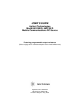
USER’S GUIDE Agilent Technologies Model 66319B/D, 66321B/D Mobile Communications DC Source Featuring programmable output resistance (Refer to page 20 for a brief description of the model differences.) Agilent Part No. 5964-8184 Microfiche No.
Warranty Information CERTIFICATION Agilent Technologies certifies that this product met its published specifications at time of shipment from the factory. Agilent Technologies further certifies that its calibration measurements are traceable to the United States National Bureau of Standards, to the extent allowed by the Bureau's calibration facility, and to the calibration facilities of other International Standards Organization members.
Safety Summary The following general safety precautions must be observed during all phases of operation of this instrument. Failure to comply with these precautions or with specific warnings elsewhere in this manual violates safety standards of design, manufacture, and intended use of the instrument. Agilent Technologies assumes no liability for the customer's failure to comply with these requirements. GENERAL This product is a Safety Class 1 instrument (provided with a protective earth terminal).
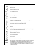
SAFETY SYMBOLS Direct current Alternating current Both direct and alternating current Three-phase alternating current Earth (ground) terminal Protective earth (ground) terminal Frame or chassis terminal Terminal is at earth potential. Used for measurement and control circuits designed to be operated with one terminal at earth potential.
Declaration Page DECLARATION OF CONFORMITY according to ISO/IEC Guide 22 and EN 45014 Manufacturer's Name: Manufacturer's Address: Agilent Technologies, Inc. 140 Green Pond Road Rockaway, New Jersey 07866 U.S.A.
DECLARATION OF CONFORMITY according to ISO/IEC Guide 22 and EN 45014 Manufacturer's Name: Manufacturer's Address: Agilent Technologies, Inc. 140 Green Pond Road Rockaway, New Jersey 07866 U.S.A.
Acoustic Noise Information Herstellerbescheinigung Diese Information steht im Zusammenhang mit den Anforderungen der Maschinenläminformationsverordnung vom 18 Januar 1991. * Schalldruckpegel Lp <70 dB(A) * Am Arbeitsplatz * Normaler Betrieb * Nach EN 27779 (Typprüfung). Manufacturer's Declaration This statement is provided to comply with the requirements of the German Sound Emission Directive, from 18 January 1991.
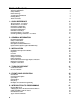
Table of Contents Warranty Information Safety Summary Declaration Page Acoustic Noise Information Printing History Table of Contents 1 - QUICK REFERENCE The Front Panel - At a Glance The Rear Panel - At a Glance Instrument Configuration Front Panel Number Entry Front Panel Annunciators Immediate Action Keys Front Panel Menus - At a Glance SCPI Programming Commands - At a Glance 2 - GENERAL INFORMATION Document Orientation Safety Considerations Options and Accessories Description and Model Differences Opti
Types of SCPI Messages SCPI Data Formats SCPI Command Completion Using Device Clear SCPI Conformance Information 7 - PROGRAMMING THE DC SOURCE 65 67 68 68 69 71 Introduction Programming the Output Triggering Output Changes Making Basic Measurements Making Enhanced Measurements Making DVM Measurements Triggered Measurements Programming the Status Registers Inhibit/Fault Indicator 71 71 73 75 76 79 80 84 89 8 - LANGUAGE DICTIONARY 91 Introduction Calibration Commands Display Commands Measurement Comma
1 Quick Reference The Front Panel - At a Glance 1 A 14-character display shows output measurements and programmed values. 1 2 Annunciators indicate 3 Rotary control sets voltage, operating modes and status conditions. current, and menu parameters. Use " and ! to set the resolution; then adjust the value with the knob. 2 3 66319D DUAL OUTPUT Mobile Communications DC Source CV Unr CC Dis OCP Prot SYSTEM Channel 1 Save 6 Addr Err SRQ ENTRY OV Meter 3 Voltage 4 5 Prot Cir 7 .
1 - Quick Reference The Rear Panel - At a Glance 1 DVM inputs. 2 GPIB (IEEE-488) 3 Used to connect the 4 INH/FLT connector. Can Connector plug is removable. interface connector. Agilent 14575A remote front panel display. be configured for Digital I/O and Trigger input. Connector plug is removable. 2 1 WARNING: 3 NO OPERATOR SERVICEABLE PARTS 4 REFER SERVICING TO SERVICE TRAINED INH FLT + - - + + ! DVM OUTPUT 2 0 - 12V / 0 - 1.
Quick Reference - 1 Front Panel Number Entry Enter numbers from the front panel using one the following methods: Use the arrow keys and knob to change voltage or current settings NOTE: The output must be ON to see the displayed values change in Meter mode. With the output enabled, this method changes the output voltage or current immediately.
1 - Quick Reference Front Panel Annunciators CV Output 1 or output 2 is operating in constant voltage mode. CC Output 1 or output 2 is operating in constant current mode. Unr Output 1 or output 2 is unregulated. Dis The output is OFF. Press the Output On/Off key to turn the output on. OCP The over-current protection state is ON. Press the OCP key to turn over-current protection off. Prot Indicates that the output has been disabled by one of the protection features.
Quick Reference - 1 Front Panel Menus - At a Glance Address $ $ $ $ Recall Shift Save Shift Error Shift Channel Meter $ $ $ $ $ $ $ $ $ $ $ $ Voltage Current Shift Res Protect Output $ $ $ $ $ $ $ $ $ $ $ Shift OV $ Shift Input $ $ $ Shift Cal ADDRESS 7 LANG SCPI REMOTE FP OFF ROM: A.00.00 SN: US12345678 *RCL 0 *SAV 0 ERROR 0 2 5.000V 0.104A 1 12.000V 1 0.204A 1 12.500V MAX 1 1.000V MIN 1 12.330V HIGH 1 0.080V LOW 1 12.000V RMS 1 0.350A MAX 1 0.050A MIN 1 0.400A HIGH 1 0.012A LOW 1 0.
1 - Quick Reference SCPI Programming Commands - At a Glance NOTE: Some [optional] commands have been included for clarity. Refer to chapter 8 for a complete description of all programming commands.
2 General Information Document Orientation This manual describes the operation of the Agilent Model 66321B/D Mobile Communications and the Agilent Model 66319B/D Dual Output DC Source. Agilent Models 66321D and 66319D have an additional DVM measurement input on the rear panel. Unless otherwise noted, all models will be referred to by the description "dc source" throughout this manual.
2 - General Information Safety Considerations This dc source is a Safety Class 1 instrument, which means it has a protective earth terminal. That terminal must be connected to earth ground through a power source equipped with a ground receptacle. Refer to the Safety Summary page at the beginning of this guide for general safety information. Before installation or operation, check the dc source and review this guide for safety warnings and instructions.
General Information - 2 Description and Model Differences Agilent 66321B The Agilent 66321B Mobile Communications DC Source is a high performance dc power source that provides peak current sourcing and rapid, basic measurements in a compact, half-rack box. It is designed to simplify the testing of digital wireless communications products. Excellent voltage transient response characteristics prevent test interruptions due to triggering of low voltage phone shutdown.
2 - General Information ! ! Triggered acquisition of digitized current and voltage waveforms External measurement trigger input on units with firmware revision A.03.01 and up ♦ Open sense lead protection on output 1. ♦ Automatic overvoltage protection tracking. ♦ Over-temperature, RI/DFI protection features, programmable voltage limit and current limit. ♦ Non-volatile state storage and recall with SCPI command language. ♦ User-configurable power-on/reset settings (see Appendix B). Table 2-3.
General Information - 2 Output 1 Characteristic The dc source's main output (output 1) characteristic is shown in the following figure. The main output of the dc source may be adjusted to any value within the boundaries shown. Output Voltage ISET 15V -1.2A 1 stive load line VSET CV resi 2 CC -2.8A 0 el tiv s i res d oa e lin Peak Current capability for up to 7 ms shown by dotted lines + 3A 5A Output Current Figure 2-1.
2 - General Information NOTE: Operating the dc source beyond its output ratings may cause the output to become unregulated. This is indicated by the UNR annunciator on the front panel. The output may also become unregulated if the ac line voltage drops below the minimum rating specified in Appendix A. Programmable Output Resistance Programmable output resistance lets you emulate the internal resistance of a cell phone battery, which causes the voltage at the phone to drop as the phone draws more current.
General Information - 2 Option 521 Description (Agilent 66319B/D only) Option 521 consists of the following enhancements to the output capabilities of Agilent models 66319B/66319D: ♦ Solid-state relays to connect and disconnect the output of the dc source. The relays are available on the output and sense terminals of outputs 1 and 2. When the solid state relays are open, the output impedance is effectively raised to about 500k ohms for output 1, and about 200k ohms for output 2.
3 Installation Installation and Operation Checklist Check the Output Compensation # Check that the output compensation of the dc source is appropriate for your application. Refer to “Output Compensation” in this chapter. HRemote mode provides the best transient response and can be used with phones having input capacitances from 5µF to 12000µF.
3 - Installation Inspection Damage When you receive your dc source, inspect it for any obvious damage that may have occurred during shipment. If there is damage, notify the shipping carrier and the nearest Agilent Sales and Support Office immediately. The list of Agilent Sales and Support Offices is at the back of this guide. Warranty information is printed in the front of this guide.
Installation - 3 Location Figure 3-1 gives the dimensions of your dc source. The dc source must be installed in a location that allows sufficient space at the sides and back of the unit for adequate air circulation (see Bench Operation). NOTE: This dc source generates magnetic fields that may affect the operation of other instruments. If your instrument is susceptible to operating magnetic fields, do not locate it in the immediate vicinity of the dc source.
3 - Installation Input Connections Connect the Power Cord Connect the power cord to the IEC 320 connector on the rear of the unit. If the wrong power cord was shipped with your unit, contact your nearest Agilent Sales and Support Office to obtain the correct cord (refer to the list at the back of this guide). Check the line voltage rating label on the back of the unit to make sure that it agrees with your ac mains voltage.
Installation - 3 Voltage Drops and Lead Resistance To optimize the performance and transient response in your test system, please observe the following guidelines: ♦ Twist the load leads together and keep them short. The shorter the leads, the better the performance. ♦ When remote sensing, twist the sense leads together but do not bundle them in with the load leads. ♦ For best performance, keep the total cable length to the load to 20 ft or less when remote sensing.
3 - Installation OUTPUT 1/OUTPUT 2 CONNECTOR -S - + +S TWIST LEADS TWIST PAIR + LOAD _ WIRE RESISTANCE Figure 3-2. Remote Sense Connections Connect the remote sense leads only to the remote sense connections at the output connector and at the location on the test fixture where you want to sense the output voltage. There must be not be any continuity from the sense leads to earth ground or from the sense leads to the output leads other than at the test fixture.
Installation - 3 Figure 3-4 shows how to connect remote sense leads when using a removable test fixture. Note that in this configuration, the wires in the part of the test fixture where the phone is located must be less than 50 cm (20 inches) in length. This is for stability as well as for the fact that the remote sense leads cannot compensate for the voltage drop in this part of the test fixture.
3 - Installation Minimizing the load lead resistance reduces voltage drops VLD+ and VLD-. ∆V can be further minimized by decreasing the resistance of the sense leads (RS+ and RS-) as much as possible. In situation where ∆V cannot be minimized any further, it may be compensated by programming a negative output resistance as previously discussed.
Installation - 3 The default setting for the open sense lead protection circuit is disabled or OFF. This is because applications that apply an external voltage to the output or that use external disconnect relays may interfere with the operation of the open sense detect circuit. If you are using external voltages or relays, you can enable the open sense detect at the beginning of the test procedure. Make sure that the external voltage is disabled and that any relays are in the closed position.
3 - Installation Refer to the previous discussion under "Remote Sense Connections" and "Local Sensing" for more information about remote and local sensing. Standard dc source units are shipped from the factory with the output compensation set to HRemote mode. This mode provides the fastest output response but requires an external capacitor for stable operation.
Installation - 3 OVP Considerations CAUTION: Disabling the overvoltage protection circuit may cause excessive output voltages, which can damage the phone under test. The dc source is shipped from the factory with its overvoltage protection (OVP) circuit enabled. This built-in overvoltage protection function is not programmable; it is set to automatically trip when the output voltage measured at the sense lead terminals exceeds the programmed voltage by two volts.
3 - Installation DVM Connections CAUTION: The DVM may be damaged if voltages at the input terminals exceed ±50 Vdc to ground. The DVM connector has three pins: plus, minus, and earth ground. The 3-pin connector is removable and accepts wires sizes from AWG 22 to AWG 14. Disconnect the mating plug by pulling it straight back. The DVM is designed as an auxiliary measurement input that can measure voltages on circuits that are powered by the main output (output 1).
Installation - 3 Because the measurement circuits of the DVM are internally referenced to the minus terminal of the main output, you must observe the following restrictions in order to guarantee accurate DVM measurements (refer to figure 3-7). Test Fixture(for illustration only) 1 R1 12V DVM 66319D 66321D 2 DVM INPUT R2 12V DVM lead resistance + V 36 V + V 2 24 V + V 3 12 V + V 4 V 5 -2V + V 6 -4V + V 7 -6V + V NOTE: The DVM common mode voltage range is from -4.5Vdc to +25Vdc.
3 - Installation Measuring Circuits that are Floating with Respect to the Main Output In the example shown in figure 3-8, the common mode voltage between the DVM inputs and the minus terminal of the main output (output 1) includes an undefined floating voltage that may result in incorrect readings due to clipping by the internal DVM measurement circuits. This will occur when the −4.5 Vdc to + 25 Vdc common mode voltage range is exceeded.
Installation - 3 PIN 1 2 3 4 Table 3-3. 4-Pin Connector Configurations TRIGGER FAULT/INHIBIT Not used FLT Output Not used FLT Common Trigger Input INH Input Trigger Common INH Common DIGITAL I/O Output 0 Output 1 Input/Output 2 Common When functioning in Fault/Inhibit mode, the fault (FLT) output, also referred to as the DFI (discrete fault indicator) signal, is an open collector circuit that pulls the positive output low with respect to the negative (chassis-referenced) common.
3 - Installation Digital I/O Connections As shown in Table 3-3 and Figure 3-10, the 4-pin connector can also be configured as a digital I/O port. Information on programming the digital I/O port is found in chapter 5 and under [SOURce:]DIGital:DATA and [SOURce:]DIGital:FUNCtion commands in chapter 8. The electrical characteristics of the digital connector are described in appendix A. +16.5V Max. Digital Output Ports 0, 1, 2 TTL, AS, CMOS, HC Coil Current 0.25A Max.
4 Turn-On Checkout Checkout Procedure Successful tests in this chapter provide a high degree of confidence that your unit is operating properly. For performance tests, see appendix B. NOTE: To perform the checkout procedure, you will need a wire for shorting the output terminals together. The following procedure assumes that the unit turns on in the factory-default state. If you need more information about the factory default state, refer to the *RST command in chapter 8.
4 - Turn-On Checkout Procedure Display Explanation 7. Plug the output connector back into the unit. 8. Press Shift, Prot Clear NO FAULT Clears the protection condition. Prot is off; CV is on. 9. Press Voltage VOLT 0.000 Display shows the output voltage setting of the unit. 10. Press Enter Number, <15>, Enter VOLT <15> 15.003V 0.0001A Programs the main output to 15 volts. After the value is entered, the display returns to Meter mode.
Turn-On Checkout - 4 Procedure Display Explanation Shorts output 2 of the unit. 23. Connect a jumper wire across the + and terminals of output 2. 24. Press Output On/Off. 25. Press Current, Enter Number, <1>, Enter. 26. Press Shift, OCP 2 0.001V 0.0003A You enabled the overcurrent protection circuit. The circuit then tripped because output 2 was operating in constant current mode. The CC annunciator turns off, and the OCP and Prot annunciators turn on. 27. Press Shift, OCP 2 0.001V 0.
4 - Turn-On Checkout Runtime Error Messages Appendix C lists other error messages that may appear at runtime. Some of these messages will also appear on the front panel when the Prot key is pressed. To clear the error, you must remove the condition that caused the error and then press the Prot Clear key. Table 4-2.
5 Front panel Operation Introduction Here is what you will find in this chapter: ♦ ♦ a complete description of the front panel controls front panel programming examples NOTE: The dc source must be in set to Local mode to use the front panel controls. Press the Local key on the front panel to put the unit in local mode.
5 – Front Panel Operation 1 Display 14-character vacuum fluorescent display for showing output measurements and programmed values. 2 Annunciators Annunciators light to indicate operating modes and status conditions: CV The dc source output is in constant-voltage mode. CC The dc source output is in constant-current mode. Unr The dc source output is in an unregulated state. Dis The dc source output is disabled (off). OCP The overcurrent protection state is enabled.
Front Panel Operation - 5 System Keys Refer to the examples later in this chapter for more details on the use of these keys. SYSTEM Channel Error Local Address Save Recall Figure 5-2. System Keys This is the blue, unlabeled key, which is also shown as Shift in this guide. Pressing this key accesses the alternate or shifted function of a key (such as ERROR ). Release the key after you press it. The Shift annunciator is lit, indicating that the shifted keys are active.
5 – Front Panel Operation Function Keys Refer to the examples later in this chapter for more details on the use of these keys. FUNCTION Input OV Res Meter Voltage Output Prot Cir OCP Cal Protect Current Output On/Off Figure 5-3. Function Keys Immediate Action Keys Immediate action keys immediately execute their corresponding function when pressed. Other function keys have commands underneath them that are accessed when the key is pressed.
Front Panel Operation - 5 Metering Keys Metering keys control the metering functions of the dc source. As set from the factory, all front panel measurements from the main output (output 1), are calculated from a total of 2048 readings taken at a 46.8 microsecond sampling rate. Therefore, the factory default acquisition time for a single front panel measurement is about 100 milliseconds.
5 – Front Panel Operation Output Control Keys Output control keys control the output functions of the dc source. Voltage Press this key to access the voltage menu. Display Command Function 1 VOLT VOLT 1 LIMIT 2 Current Press this key to access the current menu.
Front Panel Operation - 5 Entry Keys Refer to the examples later in this chapter for more details on the use of these keys. ENTRY Cir Entry 1 2 3 4 5 . 6 7 8 9 0 - Enter Number Enter Backspace Figure 5-4. Entry Keys # & " ! Enter Number 0 . , Back space Shift Clear Entry Enter These keys let you scroll through choices in a parameter list that apply to a specific command. Parameter lists are circular; you can return to the starting position by continuously pressing either key.
5 – Front Panel Operation Examples of Front Panel Programming You will find these examples on the following pages: 1 Using the front panel display 2 Setting the output voltage, current, and compensation 3 Setting the output 2 voltage and current 4 Querying and clearing output protection 5 Making basic front panel measurements 6 Making enhanced front panel measurements 7 Making DVM measurements 8 Programming the digital port 9 Setting the GPIB address 10 Storing and recalling instrument states 1 - Using th
Front Panel Operation - 5 Set the output voltage Action Display 1. To enter an approximate value without using the voltage menu: On the Entry keypad, press " or ! to select the 1's digit in the voltage field. Then rotate the front panel RPG knob to obtain 7 V. If the unit is in CC mode, you won't see the output voltage change until the voltage setting is low enough to cause the unit to go into CV mode. 7.003V 0.004A 2. The easiest way to enter an accurate value: On the Function keypad, press Voltage.
5 – Front Panel Operation Setting the relay mode (Agilent 66319B/66319D with Option 521 only) Action 1. Use Output ON/OFF to make sure that the output of the selected channel is off. The output must be turned off before any relay settings take effect. If the Dis annunciator is lit, the output is off. 2. Press Meter to return the display to Meter mode. 3. Press Shift Channel to select either output channel 1 or output channel 2. Display 1 2 4. On the Function keypad, press OUTPUT.
Front Panel Operation - 5 3. To make minor changes to an existing value, press Current. The procedure to change an individual digit is explained in step 3 under "Set the output 2 voltage." NOTE: To draw current pulses greater than 1.5 A and up to 2.5 A peak on output 2, set the output current limit higher than 1.5 amperes (1.52 amperes max). Do not enable OCP, or else make sure that the protection delay setting is longer than the expected current pulse. Enable the output 1.
5 – Front Panel Operation 5 – Making Basic Front Panel Measurements As shipped from the factory, front panel measurements for the main output (output 1) are calculated from a total of 2048 readings taken at a 46.8 microsecond sampling rate. The unit alternates between voltage and current measurements. Therefore, the data acquisition time for a single front panel voltage or current measurement is about 100 milliseconds.
Front Panel Operation - 5 6 – Making Enhanced Front Panel Measurements The following figure illustrates the enhanced measurement capabilities of Agilent Models 66321B/D and 66319B/D for measuring output waveforms. These include peak (max), minimum, high level, and low level measurements as illustrated in the following figure. Rms and dc voltages are calculated from the number of points in the measurement window. V or A MAX 46.
5 – Front Panel Operation 3. Continue by pressing Shift, Input and ( until you obtain the POINT command. Press & to select a different buffer size. The choices are: 1, 2, 4, 8, 16, 32, 64, 128, 256, 512, 1024, and 2048. Then press Enter. POINT 1024 One reason to change the front panel time interval and data points is if the waveform being measured has a period shorter than 3 times the present front panel acquisition time. 4. For current measurements, press Shift, Input.
Front Panel Operation - 5 8 - Programming Output Port Functions You can configure the output port to perform three different functions. In RIDFI mode, the port functions as a remote inhibit input with a discrete fault indicator output signal. In DIGIO mode, the port acts as a digital Input/Output device. In TRIGGER mode, the port accepts external measurement trigger signals. To configure the RIDFI mode of the port, proceed as follows: Action Display 1. On the Function keypad, press Output. *RST 2.
5 – Front Panel Operation 10 - Storing and Recalling Instrument States You can save up to 4 states (from location 0 to location 3) in non-volatile memory and recall them from the front panel. All programmable settings are saved. This capability is only available when the unit is set to the SCPI programming language. NOTE: You can program the unit to automatically power-on according to the instrument state that is saved in state 0 as shown in the third example.
6 Introduction to Programming External References GPIB References The most important GPIB documents are your controller programming manuals - BASIC, GPIB Command Library for MS DOS, etc. Refer to these for all non-SCPI commands (for example: Local Lockout). The following are two formal documents concerning the GPIB interface: ♦ ANSI/IEEE Std. 488.1-1987 IEEE Standard Digital Interface for Programmable Instrumentation. Defines the technical details of the GPIB interface.
6 - Introduction to Programming VXIplug&play Power Products Instrument Drivers VXIplug&play instrument drivers for Microsoft Windows 95 and Windows NT are now available on the Web at http://www.agilent.com/find/drivers. These instrument drivers provide a high-level programming interface to your Agilent Technologies instrument. VXIplug&play instrument drivers are an alternative to programming your instrument with SCPI command strings.
Introduction to Programming - 6 Accessing Online Help A comprehensive online programming reference is provided with the driver. It describes how to get started using the instrument driver with Agilent VEE, LabVIEW, and LabWindows. It includes complete descriptions of all function calls as well as example programs in C/C++ and Visual BASIC. ( To access the online help when you have chosen the default Vxipnp start folder, click on the Start button and select Programs | Vxipnp | Agxxxx Help (32-bit).
6 - Introduction to Programming Types of SCPI Commands SCPI has two types of commands, common and subsystem. ♦ Common commands generally are not related to specific operation but to controlling overall dc source functions, such as reset, status, and synchronization. All common commands consist of a three-letter mnemonic preceded by an asterisk: *RST *IDN? *SRE 8 ♦ Subsystem commands perform specific dc source functions. They are organized into an inverted tree structure with the "root" at the top.
Introduction to Programming - 6 Moving Among Subsystems In order to combine commands from different subsystems, you need to be able to reset the header path to a null string within a message. You do this by beginning the command with a colon (:), which discards any previous header path.
6 - Introduction to Programming Data Message Unit Keywords VOLT : LEV 20 ; Query Indicator PROT 21 Keyword Separator Message Unit Separators ; : CURR? Message Terminator Root Specifier Figure 6-2. Command Message Structure Headers Headers, also referred to as keywords, are instructions recognized by the dc source. Headers may be either in the long form or the short form. In the long form, the header is completely spelled out, such as VOLTAGE, STATUS, and DELAY.
Introduction to Programming - 6 SCPI Data Formats All data programmed to or returned from the dc source is ASCII. The data may be numerical or character string. Numerical Data Formats Symbol Response Formats Digits with an implied decimal point assumed at the right of the least-significant digit. Examples: 273 Digits with an explicit decimal point. Example: .0273 Digits with an explicit decimal point and an exponent. Example: 2.
6 - Introduction to Programming SCPI Command Completion SCPI commands sent to the dc source are processed either sequentially or in parallel. Sequential commands finish execution before a subsequent command begins. Parallel commands allow other commands to begin executing while the parallel command is still executing. Commands that affect trigger actions are among the parallel commands.
Introduction to Programming - 6 SCPI Conformance Information SCPI Conformed Commands The Agilent 66321B/D and 66319B/D conform to SCPI Version 1995.0.
7 Programming the DC Source Introduction This chapter contains examples on how to program your dc source. Simple examples show you how to program: $ output functions such as voltage, current, and resistance $ internal and external triggers $ measurement functions $ the status and protection functions NOTE: The examples in this chapter show which commands are used to perform a particular function, but do not show the commands being used in any particular programming environment.
7 - Programming the DC Source Maximum Voltage The maximum output voltage that can be programmed can be queried with: VOLT? MAX Overvoltage Protection The dc source will turn off its output if the output voltage exceeds its programmed setting by two volts when measured at the + sense and − sense terminals. If the operation of the overvoltage protection circuit interferes with the proper operation of your phone test, you can disable overvoltage protection.
Programming the DC Source - 7 Triggering Output Changes The dc source has two independent trigger systems. One is used for synchronizing output changes, and the other is used for synchronizing measurements. This section describes the output trigger system. The measurement trigger system is described under "Triggering Measurements". SCPI Triggering Nomenclature In SCPI terms, trigger systems are called sequences.
7 - Programming the DC Source Enabling the Output Trigger System When the dc source is turned on, the trigger subsystem is in the idle state. In this state, the trigger subsystem is disabled, ignoring all triggers. Sending the following commands at any time returns the trigger system to the idle state: ABOR *RST *RCL The INITiate commands move the trigger system from the idle state to the initiated state. This enables the dc source to receive triggers.
Programming the DC Source - 7 Making Basic Measurements All dc sources have excellent output voltage and current measurement capability. NOTE: There is only one measurement system in the dc source. Therefore, you can perform only one measurement function (voltage, current, or DVM) at a time. All measurements are performed by digitizing the instantaneous output voltage or current for a defined number of samples and sample interval, storing the results in a buffer, and then calculating the measured result.
7 - Programming the DC Source When the instrument is turned on and at *RST, the output voltage or current sampling rate is 15.6 microseconds, and the sweep size is set to 2048 data points. This means that it takes about 32 milliseconds to fill up 2048 data points in the data buffer. Adding a command processing overhead of about 20 milliseconds results in a total measurement time of about 50 milliseconds per measurement.
Programming the DC Source - 7 There are two ways to make enhanced measurements: ♦ Use the MEASure queries to immediately start acquiring new voltage or current data, and return measurement calculations from this data as soon as the buffer is full. This is the easiest way to make measurements, since it requires no explicit trigger programming. Additional calculations may be obtained from the acquired data using FETCh queries.
7 - Programming the DC Source Pulse Measurements After pulse data has been acquired, use FETCh queries to return measurement data in the shortest time. FETCh queries do not trigger the acquisition of new measurement data, but return different calculations from the data that was acquired. If you acquired voltage data, you can fetch only voltage measurements; if you acquired current data you can fetch only current measurements, otherwise an error will occur.
Programming the DC Source - 7 Returning All Measurement Data From the Data Buffer The MEASure:ARRay and FETCh:ARRay queries return all data values of the instantaneous voltage or current buffer. No weighting function is applied, returning only raw data from the buffer. The commands are: MEAS:ARR:CURR? MEAS:ARR:VOLT? Making DVM Measurements Agilent Models 66321D and 66319D have a DVM input on the rear panel for making independent voltage measurements. The common mode voltage range of the DVM is −4.
7 - Programming the DC Source Triggered Measurements Use the measurement trigger system to synchronize the acquisition of measurements with either a BUS or internal trigger. You can trigger voltage and current measurements on the main output (output 1) and on the DVM. An internal trigger synchronizes the acquisition to a signal condition. Use FETCh commands to return different calculations from the data acquired by the measurement system.
Programming the DC Source - 7 Enabling the Measurement Trigger System When the dc source is turned on, the trigger system is in the idle state. In this state, the trigger system is disabled and it ignores all triggers. Sending the following commands at any time returns the trigger system to the idle state: ABORt *RST *RCL The INITiate commands move the trigger system from the idle state to the initiated state. This enables the measurement system to receive triggers.
7 - Programming the DC Source Generating Measurement Triggers Single Triggers After you specify the appropriate trigger source and sensing function, generate triggers as follows: GPIB Triggers Send one of the following commands over the GPIB: TRIG:IMM (not affected by the trigger source setting) *TRG an IEEE-488 Group Execute Trigger bus command Internal Triggers To trigger off of the output signal, you must specify the output level that generates the trigger, the rising or falling edge of the slope, an
Programming the DC Source - 7 One way to wait for results without tying up the computer is to use the SCPI command completion commands. For example, you can send the *OPC command after INITialize, then occasionally poll the OPC status bit in the standard event status register for status completion while doing other tasks. You can also set up an SRQ condition on the OPC status bit going true and do other tasks until the SRQ interrupts.
7 - Programming the DC Source Pre-trigger and Post-trigger Data Acquisition The measurement system lets you capture data before, after, or at the trigger signal. When a measurement is initiated, the dc source continuously samples the instantaneous signal level of the sensing function. As shown in figure 7-7, you can move the block of data being read into the acquisition buffer with reference to the acquisition trigger. This permits pre-trigger or post-trigger data sampling.
Programming the DC Source - 7 Power-On Conditions Refer to the *RST command description in chapter 8 for the power-on conditions of the status registers. QUESTIONABLE STATUS CONDITION 0 OV OC N.U. FP OT OS N.U. 1 PTR/NTR 1 1 2 2 EVENT ENABLE 1 2 1 2 2 3 4 8 8 8 8 16 16 16 16 32 32 32 32 5 6-7 8 256 256 256 256 9 512 512 512 512 UNR 10 1024 1024 1024 1024 N.U. OC2 11 UNR2 RI N.U. OVLD N.U.
7 - Programming the DC Source Bit 0 5 8 9 10 11 12 0 1 3 4 5 8 9 10 12 14 0 2 3 4 5 7 3 4 5 6 7 Table 7-1.
Programming the DC Source - 7 Questionable Status Group The Questionable Status registers record signals that indicate abnormal operation of the dc source. As shown in figure 7-7, the group consists of the same type of registers as the Status Operation group. The outputs of the Questionable Status group are logically-ORed into the QUEStionable summary bit (3) of the Status Byte register.
7 - Programming the DC Source The MSS Bit This is a real-time (unlatched) summary of all Status Byte register bits that are enabled by the Service Request Enable register. MSS is set whenever the dc source has one or more reasons for requesting service. *STB? reads the MSS in bit position 6 of the response but does not clear any of the bits in the Status Byte register. The RQS Bit The RQS bit is a latched version of the MSS bit.
Programming the DC Source - 7 Step 1 Program the Operation Status PTR register to allow a positive transition at bit 10 to be latched into the Operation Status Event register, and allow the latched event to be summed into the Operation summary bit.
7 - Programming the DC Source Discrete Fault Indicator (DFI) The discrete fault indicator is an open-collector logic signal connected to the rear panel FLT connection that can be used to signal external devices when a fault condition is detected.
8 Language Dictionary Introduction This section gives the syntax and parameters for all the IEEE 488.2 SCPI commands and the Common commands used by the dc source. It is assumed that you are familiar with the material in chapter 6, which explains the terms, symbols, and syntactical structures used here and gives an introduction to programming. You should also be familiar with chapter 5, in order to understand how the dc source functions. The programming examples are simple applications of SCPI commands.
8 – Language Dictionary Table 8-1.
Language Dictionary - 8 Table 8-1.
8 – Language Dictionary Table 8-1.
Language Dictionary - 8 Common Commands Common commands begin with an * and consist of three letters (command) or three letters and a ? (query). They are defined by the IEEE 488.2 standard to perform common interface functions. Common commands and queries are categorized under System, Status, or Trigger functions and are listed at the end of the chapter. The dc source responds to the following common commands: Table 8-2.
8 – Language Dictionary Calibration Commands Calibration commands let you enable and disable the calibration mode, change the calibration password, calibrate current and voltage programming, and store new calibration constants in nonvolatile memory. NOTE: If calibration mode has not been enabled with CALibrate:STATe, programming the calibration commands will generate an error.
Language Dictionary - 8 CALibrate:CURRent:MEASure:AC This command initiates the calibration of the high bandwidth (ac) measurement circuit. Command Syntax CALibrate:CURRent:MEASure:AC Parameters None Examples CAL:CURR:MEAS:AC CALibrate:DATA This command enters a calibration value that you obtain by reading an external meter. You must first select a calibration level (with CALibrate:LEVel) for the value being entered.
8 – Language Dictionary CALibrate:RESistance This command calibrates initiates the calibration of the output resistance circuit. Command Syntax CALibrate:RESistance Parameters None Examples CAL:RES CALibrate:SAVE This command saves any new calibration constants after a calibration procedure has been completed in nonvolatile memory. If CALibrate:STATe OFF is programmed without a CALibrate:SAVE, the previous calibration constants are restored..
Language Dictionary - 8 Display Commands Display commands control the front panel display of the dc source. Annunciators are not affected. DISPlay This command turns the front panel display on or off. When off, the front panel display is blank.
8 – Language Dictionary Measurement Commands Measurement commands consist of format, measure, and sense commands. Format commands specify the data formatting of all array queries. You can specify the data type, type length, and byte order. Measure commands measure the output voltage or current. Measurements are performed by digitizing the instantaneous output voltage or current for a specified number of samples, storing the results in a buffer, and calculating the measured result.
Language Dictionary - 8 FORMat:BORDer This command selects whether the binary data is transferred in normal or swapped byte order. When NORMal is selected, the first byte sent is the sign bit and seven most significant bits of the exponent, and the last byte sent is the least significant byte of the mantissa. This ordering is generally used in bigendian controllers such as those that use Motorola processors.
8 – Language Dictionary MEASure:CURRent? [MAX | MIN | ] FETCh:CURRent? These queries return the dc output current. You can specifying an optional range parameter for the MEASure:CURent? query. This lets you use a different current range for a single measurement instance without having to change the current range using the SENSe:CURRent:RANGe command. Afer the measurement completes, the range returns to the value specified by SENSe:CURRent:RANGe.
Language Dictionary - 8 MEASure:CURRent:HIGH? FETCh:CURRent:HIGH? These queries return the High level current of a current pulse waveform. The instrument first measures the minimum and maximum data points of the pulse waveform. It then generates a histogram of the pulse waveform using 16 bins between the maximum and minimum data points. The bin containing the most data points above the 50% point is the high bin. The average of all the data points in the high bin is returned as the High level.
8 – Language Dictionary MEASure:CURRent:MINimum? FETCh:CURRent:MINimum? These queries return the minimum output current. Query Syntax MEASure[:SCALar]:CURRent:MINimum? FETCh[:SCALar]:CURRent:MINimum? Parameters None FETC:CURR:MIN? Examples MEAS:CURR:MIN? Returned Parameters Related Commands MEAS:CURR:MAX? MEASure:DVM? FETCh:DVM? Agilent 66321D/66319D only These queries measure dc voltage.
Language Dictionary - 8 MEASure:VOLTage2 Agilent 66319B/D only This query measures the output voltage at the auxiliary output. Output 2 measurements are calculated from a total of 2048 readings taken at a 15.6 microsecond sampling rate. These parameters are fixed. Query Syntax Parameters Examples Returned Parameters Related Commands MEASure[:SCALar]:VOLTage2[:DC]? None MEAS:VOLT2? FETC:VOLT2:DC? MEAS:CURR2? MEASure:VOLTage:ACDC? FETCh:VOLTage:ACDC? These queries return the ac+dc rms output voltage.
8 – Language Dictionary MEASure:VOLTage:LOW? FETCh:VOLTage:LOW? These queries return the Low level voltage of a voltage pulse waveform. The instrument first measures the minimum and maximum data points of the pulse waveform. It then generates a histogram of the pulse waveform using 16 bins between the maximum and minimum data points. The bin containing the most data points below the 50% point is the low bin. The average of all the data points in the low bin is returned as the Low level.
Language Dictionary - 8 SENSe:CURRent:DETector This command lets you select the type of detector used for output current measurements. Two choices for detecting current measurements are available: ACDC This is the preferred choice for all dynamic current measurements. When ACDC is selected, the measured output current includes the current that flows in the instrument's output capacitor.
8 – Language Dictionary SENSe:LEAD:STATus? This query returns the status of the open sense detection circuit. The query must be performed with the output disabled. Any external source such as an external capacitor must be discharged.
Language Dictionary - 8 SENSe:SWEep:POINts This command defines the number of points in a measurement. Command Syntax Parameters *RST Value Examples Query Syntax Returned Parameters Related Commands SENSe:SWEep:POINts 1 through 4096 2048 SENS:SWE:POIN 1024 SENSe:SWEep:POINts? SENS:SWE:TINT SENS:SWE:OFFS MEAS:ARR SENSe:SWEep:TINTerval This command defines the time period between samples. The value that you enter for the time interval will be rounded to the nearest 15.6 microsecond increment.
8 – Language Dictionary Output Commands Output commands consist of instrument, output and source commands. Instrument commands control the output coupling on Agilent 66319B/66319D units. Output commands control the output and digital port functions. Source commands program the actual voltage, current, and digital port output. INSTrument:COUPle:OUTPut:STATe This command controls the ON/OFF function of Output 1 and Output 2.
Language Dictionary - 8 OUTPut[1 | 2]:RELay:MODE Agilent 66319B/66319D with Option 521 only Specifies one of the relay modes (DD, DH, HD, or HH). The output must be turned off before any programmed mode settings take effect. Relay settings cannot be coupled; they must be set separately for each output. Relay modes are stored in non-volatile memory and will be restored when the unit is turned on. When shipped from the factory, the relay mode for both output 1 and output 2 is set to HH.
8 – Language Dictionary OUTPut:COMPensation:MODE LLOCAL | LREMOTE | RLOCAL | RREMOTE LLOCAL OUTP:COMP:MODE HREMOTE OUTPput:COMPensation:MODE? OUTP:TYPE[:CAPacitance] (LOW mode corresponds to (Agilent 66311B/D, 66309B/D) LLocal; HIGH mode corresponds to HRemote) Command Syntax Parameters *RST Value Examples Query Syntax Returned Parameters Backward Compatibility OUTPut:DFI This command enables or disables the discrete fault indicator (DFI) output from the dc source.
Language Dictionary - 8 OUTPut:PROTection:CLEar This command clears the latch that disables the output when an overvoltage, overcurrent, overtemperature, or remote inhibit status condition is detected. All conditions that generate the fault must be removed before the latch can be cleared. The output is then restored to the state it was in before the fault condition occurred.
8 – Language Dictionary [SOURce:]CURRent This command sets the immediate current level of the dc source. The immediate level is the current programmed for the output terminals.
Language Dictionary - 8 [SOURce:]CURRent:TRIGger This command sets the pending triggered current level of the dc source. The pending triggered level is a stored current value that is transferred to the output terminals when a trigger occurs. In order for a trigger to occur, the trigger subsystem must be initiated (see the INITiate command in the trigger subsystem).
8 – Language Dictionary Command Syntax Parameters *RST Value Examples Query Syntax Returned Parameters [SOURce:]DIGital:DATA[:VALue] 0 to 7 0 DIG:DATA 7 [SOURce:]DIGital:DATA? [SOURce:]DIGital:FUNCtion Configures the 4-pin control port. The configuration setting is saved in non-volatile memory.
Language Dictionary - 8 [SOURce:]VOLTage This command sets the output voltage level of the dc source. Command Syntax Parameters Default Suffix *RST Value Examples Query Syntax Returned Parameters Related Commands [SOURce:]VOLTage[:LEVel][:IMMediate][:AMPLitude] see Table 8-3 V (volts) 0 VOLT 2.5 !set output voltage to 2.
8 – Language Dictionary [SOURce:]VOLTage:PROTection:STATe This command enables or disables the automatic overvoltage protection tracking (OVP) function. It does not disable the programmable VOLTage:PROTection level. CAUTION: Disabling the overvoltage protection function may cause excessive output voltages, such as can occur if remote sense leads are disconnected, to damage the equipment under test.
Language Dictionary - 8 Status Commands Status commands program the dc source status registers. The dc source has three groups of status registers; Operation, Questionable, and Standard Event. The Standard Event group is programmed with Common commands as described later in this section. The Operation and Questionable status groups each consist of the Condition, Enable, and Event registers and the NTR and PTR filters.
8 – Language Dictionary STATus:OPERation:ENABle This command and its query set and read the value of the Operational Enable register. This register is a mask for enabling specific bits from the Operation Event register to set the operation summary bit (OPER) of the Status Byte register. This bit (bit 7) is the logical OR of all the Operatonal Event register bits that are enabled by the Status Operation Enable register.
Language Dictionary - 8 STATus:QUEStionable? This query returns the value of the Questionable Event register. The Event register is a read-only register which holds (latches) all events that are passed by the Questionable NTR and/or PTR filter. Reading the Questionable Event register clears it. Query Syntax Parameters Examples Returned Parameters Related Commands STATus:QUEStionable[:EVENt]? None STAT:QUES? (register value) *CLS STAT:QUES:ENAB STAT:QUES:NTR STAT:QUES:PTR Table 8-5.
8 – Language Dictionary STATus:QUEStionable:NTR STATus:QUEStionable:PTR These commands allow you to set or read the value of the Questionable NTR (Negative-Transition) and PTR (Positive-Transition) registers.
Language Dictionary - 8 System Commands System commands control system functions that are not directly related to output control or measurement functions. SYSTem:ERRor? This query returns the next error number followed by its corresponding error message string from the remote programming error queue. The queue is a FIFO (first-in, first-out) buffer that stores errors as they occur. As it is read, each error is removed from the queue. When all errors have been read, the query returns 0,NO ERROR.
8 – Language Dictionary Trigger Commands Trigger commands consist of trigger and initiate commands. They are used to generate output transients and measurement triggers. Initiate commands initialize the trigger system. Trigger commands control the remote triggering of the dc source. Trigger commands (and Initate commands) are referenced either by name or by number.
Language Dictionary - 8 INITiate:CONTinuous:SEQuence1 INITiate:CONTinuous:NAME TRANsient These commands control the output transient trigger system. continuously initiates the output trigger system.. 1 or ON turns off continuous triggering. In this state, the output trigger system must be initiated 0 or OFF for each trigger using INITiate:SEQuence.
8 – Language Dictionary TRIGger:SEQuence2 TRIGger:ACQuire These commands generate a BUS trigger for the measurement trigger system. When the measurement trigger system is enabled, the measurement trigger causes the dc source to measure either the voltage or current on the main output or the DVM inputs and store the results in a buffer. The SENSe:FUNCtion command selects the signal that will be measured.
Language Dictionary - 8 TRIGger:SEQuence2:COUNt:VOLTage TRIGger:ACQuire:COUNt:VOLTage This command sets up a successive number of triggers for measuring voltage data. With this command, the trigger system needs to be initialized only once at the start of the acquisition period. After each completed measurement, the instrument waits for the next valid trigger condition to start another measurement. This continues until the count has completed.
8 – Language Dictionary TRIGger:SEQuence2:HYSTeresis:DVM TRIGger:ACQuire:HYSTeresis:DVM Agilent 66321D/66319D only This command defines a band around the trigger level through which the input signal must pass before a DVM measurement can occur. The band limit above and below the trigger level is one half of the hysteresis value added to or subtracted from the trigger level.
Language Dictionary - 8 TRIGger:SEQuence2:LEVel:CURRent TRIGger:ACQuire:LEVel:CURRent This command sets the trigger level for internally triggered current measurements. A positive current trigger occurs when the current level changes from a value less than the lower hysteresis band limit to a value greater than the upper hysteresis band limit.
8 – Language Dictionary TRIGger:SEQuence2:LEVel:VOLTage TRIGger:ACQuire:LEVel:VOLTage This command sets the trigger level for internally triggered voltage measurements. A positive voltage trigger occurs when the voltage level changes from a value less than the lower hysteresis band limit to a value greater than the upper hysteresis band limit.
Language Dictionary - 8 Command Syntax TRIGger:SEQuence2:SLOPe:DVM TRIGger:ACQuire:SLOPe:DVM Parameters EITHer | POSitive | NEGative *RST Value POSitive Examples TRIG:SEQ2:SLOP:DVM POS TRIG:ACQ:SLOP:DVM EITH Query Syntax TRIGger:SEQuence2:SLOPe:DVM? TRIGger:ACQuire:SLOPe:DVM? Returned Parameters Related Commands TRIG:SEQ2:LEV:DVM TRIGger:SEQuence2:SLOPe:VOLTage TRIGger:ACQuire:SLOPe:VOLTage This command sets the slope of an internally triggered voltage measurement.
8 – Language Dictionary TRIGger:SEQuence1:DEFine TRIGger:SEQuence2:DEFine These commands define the names that are aliased to trigger sequences 1 and 2. The command accepts only ACQuire for sequence 2 and TRANsient for sequence 1 as predefined names. The query allows the user to query the instrument names aliased to sequences 1 and 2.
Language Dictionary - 8 Command Syntax Parameters Power-On Value Examples Query Syntax Returned Parameters Related Commands CAUTION: *ESE 0 to 255 (See *PSC) *ESE 129 *ESE? (Register value) *ESR? *PSC *STB? If *PSC is programmed to 0, the *ESE command causes a write cycle to nonvolatile memory. Nonvolatile memory has a finite maximum number of write cycles.
8 – Language Dictionary *OPC does not prevent processing of subsequent commands, but bit 0 will not be set until all pending operations are completed. *OPC? causes the instrument to place an ASCII "1" in the Output Queue when all pending operations are completed. Unlike *OPC, *OPC? prevents processing of all subsequent commands. It is intended to be used at the end of a command line so that the application program can then monitor the bus for data until it receives the "1" from the dc source Output Queue.
Language Dictionary - 8 *RCL This command restores the dc source to a state that was previously stored in memory with the *SAV command to the specified location.
8 – Language Dictionary *SAV This command stores the present state of the dc source to the specified location in non-volatile memory. Up to 4 states can be stored. If a particular state is desired at power-on, it should be stored in location 0. It will then be automatically recalled at power turn-on if OUTPut:PON:STATe is set to RCL0. Use *RCL to retrieve instrument states.
Language Dictionary - 8 A serial poll also returns the value of the Status Byte register, except that bit 6 returns Request for Service (RQS) instead of Master Status Summary (MSS). A serial poll clears RQS, but not MSS. When MSS is set, it indicates that the dc source has one or more reasons for requesting service. Table 8-8.
A Specifications Specifications Table A-1 lists the specifications of the dc source. Unless otherwise noted, specifications are warranted over the ambient temperature range of 0 to 55 °C. Specifications apply with typical cellular phone capacitive loads from 0µF to 12,000µF. Sensing is at the rear terminals of the power supply after a 30minute warm-up period. Sense terminals are externally jumpered to their respective output terminals. Table A-1.
A - Specifications Supplemental Characteristics Table A-2 lists the supplemental characteristics, which are not warranted but are descriptions of typical performance determined either by design or type testing. Table A-2. Supplemental Characteristics Parameter Agilent 66321B/D; Agilent 66319B/D output 1 only Agilent 66319B/D output 2 only Output Programming Range Voltage: Current: Resistance: Voltage Limit: 0 – 15.535 V 0 – 3.0712 A – 40 mΩ to 1 Ω 0 – 22 V 0 – 12.25 V 0 – 1.
Specifications - A Table A-2.
A - Specifications Table A-2. Supplemental Characteristics (continued) Parameter All Models from the date the unit is put into service Calibration Interval Listing pending: Certified to: Conforms to: Complies with: Regulatory Compliance Height: Width: Depth: Dimensions (see figure 3-1) 1 year (recommended) UL 3111-1 CSA 22.2 No. 1010.1 IEC 1010-1, EN 61010-1 EMC directive 89/336/EEC (ISM Group1 Class B) 88.1 mm (3.5in.) 212.8 mm (8.4in.) 435 mm (17.125 in.) 9.07 kg (20 lbs.) Net weight 11.1 kg (24.
B Performance, Calibration, and Configuration Introduction This appendix contains test procedures to verify that the dc source is operating normally and is within published specifications. There are four types of tests as follows: Built-in Self Tests These tests run automatically when the dc source is turned on. They check most of the digital circuits and the programming and readback DACs.
B - Performance, Calibration, and Configuration DC Power Supply 8V @ 5A (for current sink verification/calibration) 25 V source (for DVM verification/calibration) Agilent 6611C, 6631B 6631C, or 6633B GPIB Controller Full GPIB capabilities (only required if you are calibrating the unit over the GPIB) HP Series 200/300 or equivalent Oscilloscope Sensitivity: 1 mV Bandwidth Limit: 20 MHz Probe: 1:1 with RF tip Agilent 54504A or equivalent RMS Voltmeter True RMS Bandwidth: 20 MHz Sensitivity: 100 µV
Performance, Calibration, and Configuration - B Electronic Load Many of the test procedures require the use of a variable load capable of dissipating the required power. If a variable resistor is used, switches should be used to either; connect, disconnect, or short the load resistor. For most tests, an electronic load can be used.
B - Performance, Calibration, and Configuration Constant Voltage (CV) Tests CV Setup If more than one meter or if a meter and an oscilloscope are used, connect each to the terminals by a separate pair of leads to avoid mutual coupling effects. For constant voltage dc tests, connect only to +S and -S, since the unit regulates the output voltage that appears between +S and -S, and not between the (+) and (-) output terminals.
Performance, Calibration, and Configuration - B CV Source Effect (performance) This test measures the change in output voltage that results from a change in ac line voltage from the minimum to maximum value within the line voltage specifications. a. Turn off the dc source and connect the ac power line through a variable voltage transformer. b. Connect the output as shown in Figure B-1a with the DVM connected between the +S and the -S terminals. Set the transformer to nominal line voltage. c.
B - Performance, Calibration, and Configuration c. Set the load to the Constant Current mode and program the load current to 1/2 the dc source fullscale rated current. d. Set the electronic load's transient generator frequency to 100 Hz and its duty cycle to 50%. e. Program the load's transient current level to the dc source's full-scale current value and turn the transient generator on. f. Adjust the oscilloscope for a waveform similar to that in Figure B-2. g.
Performance, Calibration, and Configuration - B 1A Range Current Readback Accuracy (performance, calibration) This test verifies the readback accuracy of the 1 ampere current range. a. Turn on the dc source and set the current range readback to 1 A. Program the output voltage to 5 V and the current to 0 A. The dc source’s current detector must be set to DC. b. Divide the voltage drop (DVM reading) across the current monitoring resistor by its resistance to convert to amps and record this value (Iout).
B - Performance, Calibration, and Configuration f. Turn on the dc source and set the current range readback to 3A. Program the output voltage to zero and the current to full scale as in Table B-2. g. Record the current reading on the front panel display. Divide the voltage drop (DVM reading) across the current monitoring resistor by its resistance to convert to amperes and record this value.
Performance, Calibration, and Configuration - B CC Source Effect (performance) This test measures the change in output current that results when the AC line voltage changes from the minimum to the maximum value within the specifications. a. Turn off the dc source and connect the ac power line through a variable voltage transformer. b. Connect the output terminals as shown in Figure B-1b with the DVM connected across the current monitoring resistor. Set the transformer to the nominal line voltage. c.
B - Performance, Calibration, and Configuration Resistance Tests Resistance Programming (performance, calibration) This test verifies the resistance programming. Note that the current readback accuracy must be verified before you can perform this test. a. Turn off the dc source. Connect an electronic load directly to the output terminals of output 1 as shown in Figure B-1a. Connect an external DMM (3458) directly to the sense terminals of output 1. Turn on the dc source and select output 1.
Performance, Calibration, and Configuration - B d. Set output 1 to 15 V and repeat step c. e. Reverse the leads of the external power supply to the DVM inputs. Keep all other connections the same. f. With output 1 set to 15 V, lower the voltage on the external power supply until the external (3458) DMM reads −4.5 V. g. Record the external (3458) DMM reading and the internal DVM reading. The difference should be within the negative limits specified for the DVM in Table A-2. h.
B - Performance, Calibration, and Configuration Performance Test Record Form Model Agilent 66321B/D Model Agilent 66319B/D Output 1 Report No ______________ Test Description Minimum Specification Date __________________ Results Maximum Specification Vout − 9.5mV _________ _________ _________ _________ + 10 mV Vout + 5 mV 15.018 V Vout + 9.5 mV CV Load Effect − 5.0mV _________ + 5.0mV CV Source Effect − 0.5mV _________ + 0.
Performance, Calibration, and Configuration - B Model 66319D/66321D DVM Input Report No _______________ Test Description Minimum Specification Date __________________ Results Maximum Specification DVM VOLTAGE CALIBRATION VERIFICATION Positive Voltage Measurement Negative Voltage Measurement Model 66319B/D Output 2 Vmeas −15mV _________ Vmeas +15mV Vmeas −6.8mV _________ Vmeas +6.
B - Performance, Calibration, and Configuration Performing the Calibration Procedure NOTE: The calibration procedure can only be performed from the front panel or using the SCPI language commands. Table B-1 lists the equipment required for calibration. Figure B-1 shows the test setup. You do not have to do a complete calibration each time. If appropriate, you may calibrate only the voltage or current and proceed to "Saving the Calibration Constants".
Performance, Calibration, and Configuration - B Front Panel Calibration Procedure These procedures assume you understand how to operate front panel keys (see chapter 5). Make sure the sense terminals are directly jumpered to the output terminals. Enable Calibration Mode Action 1. Reset the unit by selecting Output, scrolling to *RST and pressing Enter. 2. Press Output On/Off to enable the output. 3. To begin calibration press Shift Cal, scroll to CAL ON and press Enter. 4.
B - Performance, Calibration, and Configuration Output 1 Current Programming and 3A-Range Measurement Calibration NOTE: When performing a 3A-Range current calibration, you must also calibrate the 1A range, the 0.02A range, and the ac current measurement. 17. Action Connect the appropriate current monitor to the output terminals of output 1. Connect the DMM (in voltage mode) across the current shunt. Select output 1. Display 18. Press Shift Cal, scroll to CAL CURR, and press Enter. CAL:CURR 19.
Performance, Calibration, and Configuration - B AC Current Measurement Calibration 33. 34. 35. Action Disconnect all loads from the dc source but leave the sense jumpers in place. Press Shift Cal and scroll to CAL CURR MEAS AC, and press Enter. Wait for the dc source to compute the ac current calibration constant. The display returns to Meter mode when the calculation is complete. Display CAL:CURR:MEAS AC Agilent 66319B/D Output 2 Current Programming Measurement Calibration 36.
B - Performance, Calibration, and Configuration Agilent 66321D, 66319D DVM Calibration 51. Action Connect the DVM inputs directly to output 1. Connect the external DMM to the DVM inputs as shown in figure B-1e. Do not connect the Agilent 3478 DMM. 52. Press Shift Cal, scroll to CAL DVM, and press Enter. 53. Press Shift Cal, scroll to CAL LEV, and press Enter to select the first calibration point. 54.
Performance, Calibration, and Configuration - B Changing the Calibration Password The factory default password is 0. You can change the password when the dc source is in calibration mode (which requires you to enter the existing password). Proceed as follows: Action Display 1. Begin by pressing Shift Cal and scrolling to the CAL ON command. 2. Enter the existing password from Entry keypad and press Enter 3. Press Shift Cal and scroll to the CAL PASS command. 4.
B - Performance, Calibration, and Configuration The Configuration function consists of the following menu commands. Shift Cal Press this key to access the calibration menu. Local Recall Simultaneously press these keys to access the configuration menu. Display Command Function CFG EXIT Notes: CFG:FACTORY Exits the configuration menu and returns to meter mode. Also exits calibration mode. Changes not previously saved are lost. Returns the *RST state to the factory default settings.
C Error Messages Error Number List This appendix gives the error numbers and descriptions that are returned by the dc source. Error numbers are returned in two ways: ♦ Error numbers are displayed on the front panel ♦ Error numbers and messages are read back with the SYSTem:ERRor? query. SYSTem:ERRor? returns the error number into a variable and returns two parameters: an NR1 and a string. The following table lists the errors that are associated with SCPI syntax errors and interface problems.
C – Error Messages Table C-1. Error Numbers (continued –131 Invalid suffix [unrecognized units, or units not appropriate] –138 Suffix not allowed –141 Invalid character data [bad character, or unrecognized] –144 Character data too long –148 Character data not allowed –150 String data error –151 Invalid string data [e.g., END received before close quote] –158 String data not allowed –160 Block data error –161 Invalid block data [e.g.
Error Messages - C Table C-1.
D Example Programs Pulse Measurements The following programs illustrate how to make a pulse measurement over the GPIB. The measurement function is set to ACDC, which gives the best results for current waveforms that have ac content. The measurement incorporates 100 readings taken at time intervals of 20 microseconds, for a total measurement time of 2 milliseconds. The trigger point for the pulse measurement occurs at 0.1 amperes on the positive slope of the current pulse.
D – Example Programs 290 OUTPUT 705;"SENS:SWE:OFFS:POIN -20" trigger 300 OUTPUT @Ps;"INIT:NAME ACQ" 310 ! to occur. 320 OUTPUT @Ps;"FETCH:ARRAY:CURR?" completes. 330 ! 340 ENTER @Ps;Curr_array(*) 350 PRINT Curr_array(*) 360 ! 370 OUTPUT @Ps;"FETCH:CURR:MAX?" measurement.
Example Programs - D Voltage Pulse Measurement Using VISA Library Calls #include #include #include
D – Example Programs viPrintf(instrumentHandle, viPrintf(instrumentHandle, viPrintf(instrumentHandle, viPrintf(instrumentHandle, viPrintf(instrumentHandle, viPrintf(instrumentHandle, "SENS:FUNC \"VOLT\"\n"); "TRIG:ACQ:LEV:VOLT %.5lg\n", 2.75); "TRIG:ACQ:HYST:VOLT %.5lg\n", 0.1); "TRIG:ACQ:SLOP:VOLT POS\n"); "TRIG:ACQ:COUN:VOLT %ld\n", 1); "TRIG:ACQ:SOUR INT\n"); /* initiate the acquisition system for measurement trigger */ printf ("Arm acquisition system...
Example Programs - D When this program runs, it returns the DC, RMS, MIN, MAX, HIGH, and LOW data in 10 measurement data points in the following format: Output Voltage = 1.999860; Output Current = -0.000043 Arm acquisition system... Pre-trigger delay... Trigger acquisition... Dynamic voltage measurements: dc = 5.002660 V rms = 5.002660 V max = 5.080140 V min = 1.996970 V high= 5.002310 V low = 3.538550 V Array Data[0] = 2.000360 V Array Data[1] = 1.999680 V Array Data[2] = 1.998320 V Array Data[3] = 1.
E Line Voltage Conversion WARNING: Shock Hazard. Operating personnel must not remove instrument covers. Component replacement and internal adjustments must be made only by qualified service personnel. Open the Unit ♦ Turn off ac power and disconnect the power cord from the unit. ♦ Use a #15 Torx drive and remove the two screws on the bottom of the unit. If your unit has feet, you will need to remove one of the feet to access the screw.
E – Line Voltage Conversion grey orange orange 1 2 3 4 5 6 120 VAC orange Top part of transformer white/violet white/yellow 7 orange (spare) 1 2 3 4 5 6 220 VAC Top part of transformer white/violet white/yellow 7 grey Front of unit white/red/grey Front of unit grey orange (spare) grey orange orange white/red/grey 1 2 3 4 5 6 7 100 VAC Top part of transformer orange white/violet white/yellow 1 2 3 4 5 6 230 VAC Top part of transformer 7 Front of unit white/orange white/red white/blac
Index —— -- -- -- -- --, 49, 56, 57, 58 - sense open, 32 —*— *RST, 161 —+— + sense open, 32 +/- sense open, 32 +/- terminals, 28 +S/-S terminals, 28 —0— 0 ...
Index format, 100 border, 100 common command syntax, 95 common commands, 119, 123 *CLS, 132 *ESE, 132 *ESR?, 133 *IDN?, 133 *OPC, 133 *OPT?, 134 *PSC, 134 *RCL, 135 *RST, 135 *SAV, 136 *SRE, 136 *STB?, 136 *TRG, 137 *TST, 137 *WAI, 137 common mode voltage, 36 compensation, 33 configuration procedure, 161 constant current tests, 148 constant voltage tests, 146 controller connections, 40 conventions used in this guide, 63 conversion, ac line, 173 CRD, 67 crowbar circuit, 35 current, 72 maximum, 72 measurement
Index Meter, 49 OCP, 48 Output, 50 Output On/Off, 48 OV, 50 Prot Clear, 48 Protect, 50 Voltage, 50 fuse, 26 —L— —G— generating measurement triggers, 81, 82 generating triggers, 74 GP-IB, 59 address, 59, 63 capabilities of the dc source, 63 command library for MS DOS, 61 connections, 40 controller programming, 61 IEEE Std for standard codes, 61 IEEE Std for standard digital interface, 61 interface, 40 references, 61 triggers, 82 ground, earth, 18 guide, user’s, 17 —H— Hanning, 76, 109 header, 66 long form
Index MSS bit, 88 multiple triggers, 74, 83 —P— —N— negative, 131 non-volatile memory clearing, 60 storing, 47, 50 numerical data formats, 67 —O— OC, 55 OCP, 72 open sense protection, 32 operation status group, 86 option 521 description, 23 optional header example, 65 options, 18 OT, 55 output characteristic, 21 compensation, 53 connections, 28 connector, 26 control keys, 50 current setting, 53, 54 enable, 54, 55 rating, 21 relays, 23, 111 resistance, 22, 53 voltage setting, 53, 54 output 2 characteristi
Index negative, 31 sense leads, 32 resistance programming, 22 returning voltage or current data, 79 RI, 55, 89 signal, 38 RIDFI, 59 rms measurements, 77, 79 root specifier, 66 RQS bit, 88 RS-232, 59 —S— safety class, 18 safety warning, 18 saving operating states, 60 SCPI command completion, 68 command syntax, 91 command tree, 64 common commands, 64 conformance, 69 data format, 67 device clear, 68 header path, 64 message structure, 65 message types, 65 message unit, 65 multiple commands, 64 non-conformance,
Index TRIG ACQ SLOP CURR, 130 TRIG ACQ SLOP DVM, 130 TRIG ACQ SLOP VOLT, 131 TRIG ACQ SOUR, 131 TRIG SEQ1 DEF, 132 TRIG SEQ2, 126 TRIG SEQ2 COUN CURR, 126 TRIG SEQ2 COUN DVM, 126 TRIG SEQ2 COUN VOLT, 127 TRIG SEQ2 DEF, 132 TRIG SEQ2 HYST CURR, 127 TRIG SEQ2 HYST DVM, 128 TRIG SEQ2 HYST VOLT, 128 TRIG SEQ2 LEV CURR, 129 TRIG SEQ2 LEV DVM, 129 TRIG SEQ2 LEV VOLT, 130 TRIG SEQ2 SLOP CURR, 130 TRIG SEQ2 SLOP DVM, 130 TRIG SEQ2 SLOP VOLT, 131 TRIG SEQ2 SOUR, 131 TRIG SOUR, 125 trigger offset, 84 triggering outpu
Agilent Sales and Support Office For more information about Agilent Technologies test and measurement products, applications, services, and for a current sales office listing, visit our web site: http://www.agilent.com/find/tmdir You can also contact one of the following centers and ask for a test and measurement sales representative. United States: Agilent Technologies Test and Measurement Call Center P.O.
Manual Updates The following updates have been made to this manual since its publication. 1/10/01 The 14565 Remote Front Panel has been removed from Table 2-2. The Maximum current range parameter has been changed from "Max" to "3A" throughout the manual. Performance testing information has been added to Appendix B. 10/03/01 The Current Sink and Resistance Tests performance procedures have been corrected in Appendix B. 4/22/02 Mains Input Ratings have been corrected in Table A-2.