
User's Manual


124
Chapter 4: Using the Logic Analyzer in Eye Scan Mode
Setting Up and Running Eye Scan Measurements
A suitable qualification signal is rarely available. Instead, an extra
circuit (added to the SUT, in a probe adapter, or other convenient
location) is usually required to decode read/write commands and
generate the qualifier. The analyzer samples the qualification signal at
the beginning of each clock cycle (i.e. at the first of each pair of data
transfers). The analyzer can be configured to treat either the rising
edge or the falling edge of the clock as the first edge of each clock
cycle. The qualifier should remain stable for the entire duration of each
burst.
Also, the qualifier must be pipelined (delayed) by one clock cycle
before transmittal to the analyzer. The qualifier may be driven after the
clock edge (i.e. you may use the output of a flip flop) since the analyzer
has adjustable sampling positions on each input channel.
NOTE: The time range available for eye scan when the qualifier is in use depends on
the sampling position of the qualifier input in the analyzer. The range is
increased as the position is made later (as the sample position moves from
before the clock edge to after it).
The available eye scan range in 800 Mbs eye scan mode always begins at -4 ns
and goes through +8 ns + tQualSample, where tQualSample is the qualifier's
sample position as shown in the eye finder display (see Analyzer Setup,
below). The adjustment range for tQualSample is from -2.5ns through +2.5 ns.
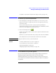
Putting it all together, the figure below shows the qualifier timing for a
pair of eight-transfer data bursts, the first of which is to be qualified for
eye scan and the second of which is to be ignored. The example shows
a system with a clock cycle beginning with a rising edge and a high-true
qualifier level. The qualifier signal to the analyzer is assumed to be the
output of a pipeline register and is therefore sampled by the analyzer
after the rising edge of the clock.