Agilent 83480A Digital Communications Analyzer Agilent 54750A Digitizing Oscilloscope Quick Start Guide
© Copyright Agilent Technologies 2000 All Rights Reserved. Reproduction, adaptation, or translation without prior written permission is prohibited, except as allowed under copyright laws. Agilent Part No. 83480-90049 Printed in USA June 2000 Agilent Technologies Lightwave Division 1400 Fountaingrove Parkway Santa Rosa, CA 95403-1799, USA (707) 577-1400 Notice. The information contained in this document is subject to change without notice.
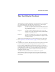
What You’ll Find in This Book What You’ll Find in This Book This book gives you a quick introduction to the instrument. It is not intended as a comprehensive guide, but rather as a starting point to start using the instrument quickly. This book is divided into three sections: Chapter 1 provides a description of the instrument and a quick tour of the front panel in a descriptive format, with examples that help to illustrate the text.
General Safety Considerations General Safety Considerations This product has been designed and tested in accordance with IEC Publication 61010-1, Safety Requirements for Electrical Equipment for Measurement, Control and Laboratory Use, and has been supplied in a safe condition. The instruction documentation contains information and warnings that must be followed by the user to ensure safe operation and to maintain the product in a safe condition.
General Safety Considerations CAUTION Before this instrument is switched on, make sure its primary power circuitry has been adapted to the voltage of the ac power source. Failure to set the ac power input to the correct voltage could cause damage to the instrument when the ac power cable is plugged in. CAUTION This product is designed for use in Installation Category II and Pollution Degree 2 per IEC 1010 and 664 respectively.
Contents General Safety Considerations iiv 1 Introducing the Instrument The Agilent 83480A, Agilent 54750A—At a Glance 1-2 A Quick Tour of the Front Panel 1-4 2 Operating the Instrument Operating the Instrument 2-2 Equipment Used in These Exercises 2-3 Exercise 1. Installing a Plug-in Module 2-4 Exercise 2. Turning On the Instrument 2-5 Exercise 3. Connecting a Signal 2-6 Exercise 4. Finding the Signal 2-7 Exercise 5. Modifying the Setup 2-8 Exercise 6. Making Measurements on the Signal 2-13 Exercise 7.
1 Entry devices 1-4 Disk drive 1-4 CAL signal 1-4 Hardkeys 1-5 Display 1-5 Softkeys 1-6 Introducing the Instrument
Introducing the Instrument The Agilent 83480A, Agilent 54750A—At a Glance The Agilent 83480A, Agilent 54750A—At a Glance The Agilent 83480A-series digital communications analyzer or Agilent 54750A-series digitizing oscilloscope are modular, high-performance mainframes that contain digitizers, timebases, and display circuitry behind vertical channel plug-in modules containing samplers, IF amplifiers, power monitoring circuitry and O/E converter (Agilent 83485A).
Introducing the Instrument The Agilent 83480A, Agilent 54750A—At a Glance Certification Agilent Technologies certifies that this product met its published specifications at the time of shipment from the factory.
Introducing the Instrument A Quick Tour of the Front Panel A Quick Tour of the Front Panel This section describes how to use the front panel. This information will help you gain the full use of your instrument in the shortest possible time. This section divides the front panel into the following areas: • Entry devices • Disk drive • CAL signal • Hardkeys • Display • Softkeys Entry devices The entry devices include the knob, arrow keys, and keypad.
Introducing the Instrument A Quick Tour of the Front Panel Hardkeys The two types of hardkeys are instant action and menu. Clear display and Run are examples of instant action keys because as soon as you press them, the instrument changes operating states. Time base and Trigger are examples of menu keys. Pressing them causes softkey menus to come up on the right side of the display. Figure 1-1.
Introducing the Instrument A Quick Tour of the Front Panel Figure 1-2. The instrument display Softkeys The softkeys are to the right of the display, and instead of placing a label on the softkey itself, the label is actually located on the display next to the softkey. These labels on the display are called menus, and the menu being displayed depends on which key has been pressed. For example, pressing Time base brings up the Time Base menu, while pressing Trigger brings up the Trigger menu.
Introducing the Instrument A Quick Tour of the Front Panel The highlighted choice is the selection that is currently active. In Figure 1-3, triggered is highlighted, which indicates that the instrument is set to triggered sweep. Figure 1-3. Toggle softkey selection Menu softkeys A typical example of the menu softkeys is External Scale... (refer to Figure 1-3 on page 1-7).
Introducing the Instrument A Quick Tour of the Front Panel Figure 1-4. Menu softkey selection Continuous softkeys A typical example of the continuous softkeys is Level. It has a range of values that can be changed with the keypad, arrow keys, or knob. Figure 1-5.
Introducing the Instrument A Quick Tour of the Front Panel Because the Trigger menu only has one of this type of softkey, it is active when the menu comes up on the display. You do not need to press the Level softkey when you want to change the trigger level. However, the Time base menu has at least two of this type of softkey, Bit Rate (Agilent 83480A only) and Scale and Position. In this case, only one of the softkeys is active at a time.
Introducing the Instrument A Quick Tour of the Front Panel You change selections by pressing the Hysteresis softkey, which brings up a second level softkey menu on the display. Then, you use the softkeys, arrow keys, or knob to change selections. To activate that selection, press the Enter softkey, then the display returns to the previous softkey menu. If you press the Cancel softkey, the instrument returns to the previous selection.
2 Equipment Used in These Exercises 2-3 Exercise 1. Installing a Plug-in Module 2-4 Exercise 2. Turning On the Instrument 2-5 Exercise 3. Connecting a Signal 2-6 Exercise 4. Finding the Signal 2-7 Exercise 5. Modifying the Setup 2-8 Exercise 6. Making Measurements on the Signal Exercise 7.
Operating the Instrument Operating the Instrument Operating the Instrument This chapter contains several exercises that will familiarize you with the operation of the instrument. Exercises 1–3 show how to get the instrument up and running. Exercises 4 and 5 demonstrate the vertical, horizontal, and trigger menus by having you display a signal and then use the channel and time base menus to expand the signal.
Operating the Instrument Equipment Used in These Exercises Equipment Used in These Exercises All of the pictures of the display in this book were generated using an Agilent 83480A with an Agilent 83483A, 54751A electrical plug-in module, and the signal from the Agilent 8133A pulse generator. If you are using a different plug-in module or signal source, your display and instrument settings may vary from the pictures in this book.
Operating the Instrument Exercise 1. Installing a Plug-in Module Exercise 1. Installing a Plug-in Module The purpose of a plug-in module is to provide measurement channels, including sampling for the mainframe. A plug-in module scales the input signal, sets the bandwidth of the system, and allows the offset to be adjusted so the signal can be viewed. The output of the plug-in module is an analog signal that is applied to the A/D converters inside the mainframe.
Operating the Instrument Exercise 2. Turning On the Instrument Exercise 2. Turning On the Instrument 1 Set the line-voltage switch on the rear panel to the correct voltage selection for your power source. 2 Connect a power cord from a power source to the rear-panel connector of the mainframe. 3 Set the rear-panel line switch to the ON position. CAUTION When the mainframe is set to the 115 VAC mode, use the supplied power cord.
Operating the Instrument Exercise 3. Connecting a Signal Exercise 3. Connecting a Signal CAUTION Electrostatic discharge (ESD) on or near input connectors can damage circuits inside the instrument. Repair of damage due to misuse is not covered under warranty. Before connecting any cable to the electrical input, momentarily short the center and outer conductors of the cable together. Personnel should be properly grounded, and should touch the frame of the instrument before touching any connector.
Operating the Instrument Exercise 4. Finding the Signal Exercise 4. Finding the Signal The purpose of this exercise is to demonstrate the Autoscale function. The Autoscale function can be used to automatically set up the display for most input signals. To activate the Autoscale function, press Autoscale. A screen similar to Figure 2-1 will be displayed.
Operating the Instrument Exercise 5. Modifying the Setup Exercise 5. Modifying the Setup The purpose of this exercise is to show you the Channel and Time Base menus. Changing the vertical scale 1 To display the Channel menu and change the vertical scaling, press: Channel (located on the plug-in module), Scale Change the scaling so the vertical height of the signal is about eight divisions, using the knob, arrow keys or keypad.
Operating the Instrument Exercise 5. Modifying the Setup Using the keypad When using the Agilent 83483A, 54751A electrical plug-in module, the knob or arrow key changes the scaling from 50 mV/div to 100 mV/div, in one step. At 50 mV/div the signal is clipped, and at 100 mV/div the signal is not expanded to take advantage of the full vertical size of the display. In this case, you can use the keypad to set the scaling to 75 mV/div.
Operating the Instrument Exercise 5. Modifying the Setup Figure 2-2. Signal vertical display Note — Agilent 83480A only You can automatically adjust the vertical scale, instead of following the preceding procedure by pressing: Channel, Channel autoscale The amplitude scale is optimized for the input signal while the timebase settings are left alone.
Operating the Instrument Exercise 5. Modifying the Setup Using the keypad 6 When the knob and arrow keys are not in the Fine mode, they operate in a 1-2-5 sequence, changing the scale from 5 ns/div to 2 ns/div in one large step. You can use Fine mode so the knob and arrow keys adjust in smaller increments, or you can use the keypad to enter a smaller value, like 1.4 ns/div.
Operating the Instrument Exercise 5.
Operating the Instrument Exercise 6. Making Measurements on the Signal Exercise 6. Making Measurements on the Signal The purpose of this exercise is to familiarize you with the Marker menu and the automatic measurement features of the instrument. You will begin by using the manual markers to make a pulse width and an amplitude measurement on channel 1. After that, you will make the same measurements using the automatic measurement features. There are many additional features built into the instrument.
Operating the Instrument Exercise 6. Making Measurements on the Signal Positioning the markers 4 To position the X1 marker, press: X1 Position Set the X1 marker to the left edge of the pulse. 5 To position the X2 marker, press: X2 Position Set the X2 marker to the right edge of the pulse. 6 To position the Y1 marker, press: Y1 Position Set the Y1 marker to the bottom of the pulse. 7 To position the Y2 marker, press: Y2 Position Set the Y2 marker to the top of the pulse.
Operating the Instrument Exercise 6. Making Measurements on the Signal Notice the ∆X and ∆Y at the bottom of the display. The ∆X value is the width measurement, and the ∆Y value is the amplitude measurement. The markers allow you to make custom measurements on signals. Remember, they are not tied directly to the waveform data stored in memory, they are just positions on the display.
Operating the Instrument Exercise 6. Making Measurements on the Signal Figure 2-5. Signal automatic measurements Displaying the scale and offset values 10 To redisplay the vertical scale and offset values, press: Shift, Clr meas The automatic measurement results are replaced by the vertical scale and offset values.
Operating the Instrument Exercise 7. Using the Help Menu Exercise 7. Using the Help Menu To display the Help menu, press Help. A screen similar to Figure 2-6 is displayed. Figure 2-6. The instrument Help menu A three-column index appears on the display. The left column lists the features of the instrument, the middle column lists the front-panel key, and (if needed) the right column lists the softkey you press to find that feature.
3 If the Mainframe Does Not Operate 3-3 If the Plug-in Does Not Operate 3-4 In Case of Difficulty
In Case of Difficulty In Case of Difficulty In Case of Difficulty This chapter provides suggestions for you to follow if the mainframe or plug-in module fails to operate. For a complete listing of display messages, refer to the Agilent 83480A, 54750A User’s Guide. For complete service information, refer to the optional Agilent 83480A, 54750A Service Guide. Review the procedure being performed when the problem occurred.
In Case of Difficulty If the Mainframe Does Not Operate If the Mainframe Does Not Operate If the mainframe does not operate, check the following: 1 Is the line fuse good? 2 Does the line socket have power? 3 Is the unit plugged in to the proper ac power source? 4 Is the mainframe turned on? 5 Is the rear-panel line switch set to on? 6 Will the mainframe power up without the plug-in module installed? If the mainframe still does not power up, refer to the optional Agilent 83480A, 54750A Service Guide or ret
In Case of Difficulty If the Plug-in Does Not Operate If the Plug-in Does Not Operate If the plug-in does not operate: 1 Make the following checks: • Is the plug-in module firmly seated in the mainframe slot? • Are the knurled screws at the bottom of the plug-in module finger-tight? • If other equipment, cables, and connectors are being used with the plug-in module, are they connected properly and operating correctly? • Review the procedure for the test being performed when the problem appeared.
In Case of Difficulty If the Plug-in Does Not Operate After viewing the signal, press triggered. • Make sure Channel Display is on by pressing: Channel, Display on off • Make sure the channel offset is adjusted so the waveform is not clipped off the display. • If you are using the plug-in module only as a trigger source, make sure at least one other channel is turned on. If all of the channels are turned off, the mainframe will not trigger.
Index Symbols duty cycle, 2-7 +width key, 2-15 E A amplitude, 2-7 measurement, 2-14 scale, 2-10 analog signal, 2-4 automatic measurement, 2-13, 2-15 Autoscale key, 2-7, 3-4 electrical plug-in module, 2-3, 2-8 Enter softkey, 1-9–1-10, 2-13 entry device overview, 1-4 equipment used for display, 2-3 expanding the signal, 2-8 External Scale softkey, 1-7 F B bandwidth, 2-4 Bit Rate softkey, 1-8 C cabinet, cleaning, iiv CAL Signal overview, 1-4 Calibrate softkey, 1-4 Cancel softkey, 1-9 care of cabinet, ii
Index M manual marker measurements, 2-15 manual softkey, 2-13 Marker key, 2-13 measuring the signal, 2-13 menu display, 1-6 key, 1-5 softkeys, 1-7 messages on display, 3-2 milli key, 2-9 mode softkey, 2-13 modifying the setup, 2-8 O offset, 2-16 adjustment, 2-4 Offset softkey, 2-9 optical/electrical plug-in module, 2-3 P plug-in module, 2-8 installing, 2-4 Position softkey, 1-8, 2-11 power cord, 2-5 pulse frequency, 2-6 generator, 2-3, 2-6 level, 2-6 R setup modification, 2-8 Shift key, 1-9 signal conn
Index X1/X2 Position softkeys, 2-14 X2, Y2 Source softkey, 2-13 Y Y1/Y2 Position softkeys, 2-14 Index-3