Agilent Technologies E1470A Cascade RF Switch Module User’s Manual *E1470-90002* Manual Part Number: E1470-90002 Printed in U.S.A.
Contents E1472A/73A/74A/75A RF Multiplexers User’s Manual AGILENT TECHNOLOGIES WARRANTY STATEMENT ............................................ 5 Safety Symbols ............................................................................................................ 6 WARNINGS ................................................................................................................. 6 Chapter 1 Configuring the RF Switch ...............................................................................
Appendix A RF Switch Specifications .......................................................................................... 39 Appendix B Register-Based Programming ................................................................................... 41 About This Appendix .................................................................................................. 41 Register Addressing...................................................................................................
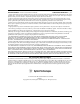
AGILENT TECHNOLOGIES WARRANTY STATEMENT AGILENT PRODUCT: E1470A Cascade RF Switch Module DURATION OF WARRANTY: 3 years 1. Agilent Technologies warrants Agilent hardware, accessories and supplies against defects in materials and workmanship for the period specified above. If Agilent receives notice of such defects during the warranty period, Agilent will, at its option, either repair or replace products which prove to be defective. Replacement products may be either new or like-new. 2.
Documentation History All Editions and Updates of this manual and their creation date are listed below. The first Edition of the manual is Edition 1. The Edition number increments by 1 whenever the manual is revised. Updates, which are issued between Editions, contain replacement pages to correct or add additional information to the current Edition of the manual. Whenever a new Edition is created, it will contain all of the Update information for the previous Edition.
DECLARATION OF CONFORMITY According to ISO/IEC Guide 22 and CEN/CENELEC EN 45014 Manufacturer’s Name: Manufacturer’s Address: Agilent Technologies, Inc. Measurement Products Unit 815 14th Street S.W. Loveland, CO 80537 USA Declares, that the product Product Name: Model Number: Product Options: Cascade RF Switch E1470A This declaration includes all options of the above product(s).
Notes: 8
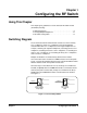
Chapter 1 Configuring the RF Switch Using This Chapter This chapter gives guidelines to use the Cascade RF Switch module (RF Switch) including: • Switching Diagram . . . . . . . . . . . . . . . . . . . . . . . . . . . . . . . . . . .9 • Creating Multiple Multiplexers. . . . . . . . . . . . . . . . . . . . . . . . . .12 • RF Switch Configuration . . . . . . . . . . . . . . . . . . . . . . . . . . . . . .
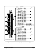
Channel Numbers Cascade Relays K001 K002 K003 COM 00 000 (3:1) 001 002 K011 K012 K014 K013 010 COM 01 (6:1) 011 012 COM 00 010 002 011 001 012 000 COM 01 COM 02 030 022 031 021 032 020 COM 03 COM 04 050 042 051 041 052 040 COM 05 K021 K022 K024 K023 COM 02 020 (9:1) 021 022 K031 K032 K034 K033 COM 03 (12:1) 030 031 032 K041 K042 K044 K043 COM 04 (15:1) 040 041 042 K051 K052 K054 050 18:1 051 COM 12 130 122 131 121 132 120 COM 13 K053 COM 05 (30:1) 12:1 052 Output to Right-S
Channel Numbers Cascade Relays 332 331 K331 K332 K334 K333 COM 33 (12:1) K321 K322 K324 K323 (9:1) 330 322 321 COM 32 320 312 COM 33 320 332 321 331 322 330 COM 32 311 COM 31 310 K311 K312 K301 K302 K314 K313 (6:1) K303 (3:1) 302 301 COM 31 300 312 301 311 302 310 COM 30 COM 30 300 12:1 Input 30:1 Input K255 252 251 12:1 (or 30:1) 250 A No Connection 18:1 COM 25 240 252 241 251 242 250 COM 24 COM 25 K256 K253 K251 K252 K254 K241 K242 K244 K243 COM 24 (15:1) K
Creating Multiple Multiplexers You can configure the Cascade RF Switch module to create multiple multiplexers of varying sizes. In its power-on/reset state, the switch is configured as 20 independent 3-to-1 multiplexers. By specifying a valid path from a COM terminal to a channel in a different bank (functionally cascading contiguous 3-to-1 multiplexers) other multiplexer sizes can be configured. Figure 1-3 shows typical 3-to-1, 6-to-1, 9-to-1, and 12-to-1 multiplexers.
COM 04 can be used for a 15-to-1 multiplexer for all channels between 000 and 042. COM 05 can be the common for all channels from 000 through 052 creating an 18-to-1 multiplexer. Multiplexers of 21-to-1, 24-to-1, and 27-to-1 can also be configured. Two 30-to-1 multiplexers can be created using channels 00 through 132 to COM 05 and channels 200 through 332 to COM 25. One 60-to-1 multiplexer can be created using all the channels to COM 25.
Setting the Logical Address The logical address of the Cascade RF Switch module is set with the Logical Address (LADDR) switch on the module. The logical address is factory-set to 120. Valid addresses are from 1 to 256. See Figure 1-4 for address switch settings. The logical address is the sum of the values of the switches set to the CLOSED position. In Figure 1-4, switches 3 through 6 are CLOSED and the associated values of these switches are 8, 16, 32, and 64.
Setting the Interrupt Request Level Interrupts are enabled at power-up, after a SYSRESET, or after resetting the module via the Control Register (see Appendix B). If interrupts are enabled, the system generates an interrupt after writing to any relay control register. The interrupt is generated approximately 13 msec after writing to the register to indicate the end of relay closure/settling time. As shown in Figure 1-5, the Interrupt Request Level switch selects the priority level that will be asserted.
Connecting User Wiring 1 User wiring connections to the module are via multiple connector blocks (part number 1250-2563). Figure 1-6 shows how to wire and assemble the connector housing. See “Cables and Connectors” for guidelines to assemble SMB jacks and connectors. See Table 1-2 in “User Wiring Log” for a log to record your wiring configuration.
Cables and Connectors The Cascade RF Switch module is shipped with a kit of 85 SMB connector jacks and 10 connector housings. You must supply your own 50Ω double-shielded cable (single-shielded cable can also be used). Agilent recommends RG188DS or RS316DS double-shielded cables or triple-shielded cable (part number 8120-0552). Standard SMB connector jacks will fit into the Cascade RF Switch module connector sockets and may be used if adjacent sockets on the module are NOT used.
User Wiring Table Table 1-2 provides a log for you to document wiring to the Cascade RF Switch module. See Figure 1-1 for terminal identification. See Figure 1-6 for guidelines to connect user wiring. You can copy the table as desired. Table 1-2.
Chapter 2 Programming the RF Switch Using This Chapter This chapter gives guidelines to program the Cascade RF Switch module (RF Switch) including: • Installing Device Drivers . . . . . . . . . . . . . . . . . . . . . . . . . . . . . .19 • Addressing the Switch . . . . . . . . . . . . . . . . . . . . . . . . . . . . . . .20 • Programming Examples . . . . . . . . . . . . . . . . . . . . . . . . . . . . . .
Addressing the Switch By specifying a path destination (a COM number) and a source (a channel number), a channel is connected to a COM terminal. The format for addressing the switch is [ROUTe:]PATH[:COMMon] , where is a 2-digit number specifying the bank for the COM terminal and is a 3-digit number specifying a channel number. (Leading 0s can be omitted.) See the [ROUTe:]PATH[:COMMon] command in Chapter 3 for valid and numbers.
Programming Examples The following C-language programs show one way to verify initial operation for the Cascade RF Switch module, to close signal paths, and to save and recall module states. To run these programs, you must have installed the E1470A SCPI Device Driver, Agilent IO Libraries for Windows, and a GPIB module in your PC.
/*Reset the E1470A */ err= viPrintf (rf_mux,"*RST;*CLS;*OPC?\n'); if (err < VI SUCCESS) err_handler (rf_mux,err); err= viScanf (rf_mux,"%s",&buf); if (err < VI_SUCCESS) err_handler (rf_mux,err); /* Read and display the ID String. Should return HEWLETT-PACKARD,E1470A,0,A.01.
Example: Closing a Signal Path This program example closes a signal path from COM 01 to channel 010 and verifies that the path is closed. #include #include #include
Example: Opening and Closing Signal Paths This program first closes a signal path from COM 01 to channel 011 and verifies that the path is closed. Next, the program closes a signal path from COM 02 to channel 010 (which opens the COM 01 to channel 011 path). Then, the program verifies that the COM 02 to channel 010 path is closed and the COM 01 to channel 011 path is open. #include #include #include
err= viPrintf (rf_mux,"PATH:COMM? 02,01\n"); if (err < VI_SUCCESS) err_handler (rf_mux,err); err = viScanf (rf_mux,"%d",&ch_closed); if (err < VI_SUCCESS) err_handler (rf_mux,err); if (ch_closed == 1) printf ("Signal path 02,010 is closed"); else printf ("Signal path 02,010 is NOT closed"); /* Close the session */ viClose (rf_mux); viClose (defaultRM); } void err_handler() /* Error handling routine */ { ViStatus err; char err_msg[1024]={0}; viStatusDesc(rf_mux,err,err_msg); printf ("Error = %s\n",err_msg);
/* Close multiple signal paths and save as state number 1 */ err = viPrintf (rf_mux,"PATH:COMM 01,011;:PATH:COMM 13,100;:PATH:COMM 31,301\n"); if (err < VI_SUCCESS) err_handler (rf_mux,err); err = viPrintf (rf_mux,"*SAV 1 \n"); if (err < VI_SUCCESS) err_handler (rf_mux,err); /* Close additional signal paths and save as state number 2 */ err= viPrintf (rf_mux,"PATH:COMM 02,010;:PATH:COMM 22,202;: PATH:COMM 24,232\n"); if (err < VI_SUCCESS) err_handler (rf_mux,err); err = viPrintf (rf_mux,"*SAV 2\n"); if (err
Chapter 3 RF Switch Command Reference This chapter describes Standard Commands for Programmable Instruments (SCPI) and summarizes IEEE 488.2 Common (*) Commands applicable to the E1470A Cascade RF Switch Module. Command Types Commands are separated into two types: IEEE 488.2 Common Commands and SCPI Commands. Common Commands Format The IEEE 488.2 standard defines the Common Commands that perform functions like reset, self-test, status byte query, etc.
For example, if the command syntax shows MEASure, then MEAS and MEASURE are both acceptable forms. Other forms of MEASure, such as MEASU or MEASUR will generate an error. You may use upper or lower case letters. Therefore, MEASURE, measure, and MeAsUrE are all acceptable. Implied Commands Implied commands are those which appear in square brackets ([ ]) in the command syntax. (The brackets are not part of the command and are not sent to the instrument.
DIAGnostic The DIAGnostic subsystem contains instrument-specific commands is are not recommended for general programming. For the E1470A, the DIAG subsystem allows you to open/close individual relays and query individual relays. Subsystem Syntax DIAGnostic :CLOSe {, ...} :CLOSe? {,...} :OPEN {,...} :OPEN? {,...} :RELAY? DIAGnostic:CLOSe DIAGnostic:CLOSe {,...} closes individual relays on the E1470A.
DIAGnostic:CLOSe? DIAGnostic:CLOSe {,...} returns a number to indicate the closed state of each relay in the list. Since these are Form C relays, “closed” means the relay is “set” (COMMON to NO). Parameters Name Comments Type numeric Range of Values 001-003|011-014|021-024|031-034|041-044| 051-056|101-103|111-114|121-124|131-134| 201-203|211-214|221-224|231-234|241-244| 251-256|301-303|311-314|321-324|331-334 Relay Closure Results.
Comments Invalid Values. Values other than those listed in the table cause error: 2022, “Invalid relay number”. Opening Relays. To open single relays, use DIAG:OPEN abc. To open multiple relays, use DIAG:OPEN abc,def,ghi,... etc. 80 Relays Maximum. The E1470A has only 80 relays. Setting more than 80 relay numbers causes error: -108, “Parameter Not Allowed”.
DIAGnostic:RELAY? DIAGnostic:RELAY? returns the relay numbers of all relays that are closed. Closed is the SET position (COMMON to NO) and is the opposite state of the power-on/reset relay state. The command can be used to determine which relays are closed by a given PATH command. Comments Output Buffer Strings. The output buffer contains an unquoted, comma-separated string of numbers where each number is a relay number. If no relay is closed, the output buffer will contain the null string.
[ROUTe:] The ROUTe subsystem automatically connects a specified channel to a specified COMMon terminal on the module. Subsystem Syntax [ROUTe:] PATH[:COMMon] , PATH[:COMMon]? , [ROUTe:]PATH[:COMMon] [ROUTe:]PATH[:COMMon], closes the E1470A path specified by and . is a 2-digit number and is a 3-digit number. Leading zeros may be omitted.
Example Closing Channel Path PATH 2,1 !Connects COMMON in Bank 02 !to channel 1 in bank 00 [ROUTe:]PATH[:COMMon]? [ROUTe:]PATH[:COMMon]?, returns either a 1 or a 0 indicating whether the specified path is closed (continuity exists) or open (the signal path is broken). is a 2-digit number and is a 3-digit number.
Example Chapter 3 Querying Paths Opened/Closed PATH 2,1 !Connects COMMON in Bank 02 !to channel 1 in bank 00 PATH? 2,1 !Returns 1 PATH? 0,002 !Returns 0 RF Switch Command Reference 35
SYSTem The SYSTem subsystem returns error numbers and error messages in the error queue of a module and the SCPI compliance year (version). Subsystem Syntax SYSTem :ERRor? :VERsion? SYSTem:ERRor? SYSTem:ERRor? returns the error numbers and corresponding error messages in the error queue. See Appendix C for a listing of the applicable error numbers and messages. Comments Error Numbers/Messages in the Error Queue: Each error records an error number and corresponding error message in the error queue.
IEEE 488.2 Common Commands Quick Reference The following table lists the IEEE 488.2 Common (*) Commands accepted by the E1470A module driver. For more information on Common Commands, see the the ANSI/IEEE Standard 488.2-1987. Command Command Description *CLS Clears all status registers and clears the error queue. *ESE Enable Standard Event. *ESE? Enable Standard Event Query. *ESR? Standard Event Register Query.
Command *WAI Command Description Wait to Complete. For the E1470A, the only pending operation is the time delay (approximately 16 msec) provided to allow the relays to settle. If this command waits longer than about 60 msec, the error -240, “Hardware error” is generated. SCPI Commands Quick Reference Description DIAGnostic:CLOSe DIAGnostic:CLOSe? DIAGnostic:OPEN DIAGnostic:OPEN? DIAGnostic:RELAY Closes individual relays. Returns a number that indicates the closed state of each relay in the list.
Appendix A RF Switch Specifications Configuration: 80 signal connections 60 inputs (channel numbers xx0 through xx2) 20 commons (channel numbers COMxx) One 60:1, two 30:1,...
Notes: 40 RF Switch Specifications Appendix A
Appendix B Register-Based Programming About This Appendix This appendix contains the information you can use for register-based programming of the E1470A Cascade RF Switch module. The contents include: • Register Addressing . . . . . . . . . . . . . . . . . . . . . . . . . . . . . . . . .41 • Register Definitions. . . . . . . . . . . . . . . . . . . . . . . . . . . . . . . . . .44 • Register Programming Example. . . . . . . . . . . . . . . . . . . . . . . .
The Base Address When you are reading or writing to a module register, a hexadecimal or decimal register address is specified. This address consists of a base address plus a register offset. The base address used in register-based programming depends on whether the A16 address space is outside or inside the E1406 Command Module.
A16 Address Space Outside the Command Module When the E1406 Command Module is not part of your VXIbus system, the E1470 base address is computed as: A16base = C000h + (LADDRh * 40h) or (decimal) A16base = 49,152 + (LADDR * 64) where C000h (49,152) is the starting location of the register addresses, LADDR is the module’s logical address, and 64 is the number of address bytes per VXI device. For example, the E1470 factory-set logical address is 120 (78h).
Table B-1.
CAUTION Registers have been documented as 8-bit bytes. If you access them using 16-bit transfers from a Motorola CPU, the high and low byte will be swapped. The E1406 uses Motorola CPUs. Motorola CPUs place the highest weighted byte in the lower memory location and the lower weighted byte in the higher memory address while Intel processors do just the opposite. VXI registers are memory-mapped. Thus, you will see this Motorola/Intel byte swap difference when doing register programming.
Relay Control Registers These registers control the individual E1470A relays. When a “1” is written to a bit, the relay controlled by that bit becomes SET (COMMON to NO). When a “0” is written to a bit, the relay controlled by that bit becomes RESET (common to NC, the power-on state). All bits are “0” at power-on and reset. Reading a bit returns the state of that bit. The left-hand relay assembly (when viewed from the front panel of the of the module) has relays K000 through K133.
Writing to Relay Control Registers To set one or more relays write a “1” to the bit controlling that relay: 1. Determine the register and bit locations for the relays you want to set. 2. Add the decimal values for each bit you want to set in a register. 3. Use the VXI:REG:WRITe command to write that decimal value to that register.
Table B-10.
Register Programming Example This example program reads the ID and Device Type registers and then reads the Status register. Next, the program closes a signal path from channel CH031 to COM 05, writes the value 20480 (5000 hexadecimal) to register 20h and then writes the value 38 (26 hexadecimal) to register 28h. Then, the program resets the module to open all channels.
if(err < VI_SUCCESS)err_handler(rf_mux,err); /* read the ID and Device Type registers */ err = viIn16(rf_mux,VI_A16_SPACE,0x00,&id_reg); if(err < VI_SUCCESS)err_handler(rf_mux,err); err = viIn16(rf_mux,VI_A16_SPACE,0x02,&dt_reg); if(err < VI_SUCCESS)err_handler(rf_mux,err); printf("ID register = 0x%4X\nDevice Type register = 0x%4X\n",id_reg,dt_reg); /* read the Status Register */ err = viIn16(rf_mux,VI_A16_SPACE,0x04,&stat_reg); if(err < VI_SUCCESS)err_handler(rf_mux,err); printf("Status register = "0x%4X
/* wait 1 second (must wait at least 100 usec before writing a "0") */ wait(1); err = viOut16(rf_mux,VI_A16_SPACE,0x04,0); if(err < VI_SUCCESS)err_handler(rf_mux,err); printf("\n\nE1470A is reset"); /* Close Session */ viClose (rf_mux); viClose (defaultRM); } /* Error Handling Routine */ void err_handler() { ViStatus err; char err_msg[1024] = {0}; viStatusDesc(rf_mux,err,err_msg); if(strcmp ("VI_SUCCESS: No error",err_msg) != 0) printf("ERROR = %s\n",err_msg); return; } void wait (int wait_seconds) /* Wait
Notes: 52 Register-Based Programming Appendix B
Appendix C RF Switch Error Messages The following error messages are unique to the E1470A. See the appropriate command module or VXI Controller module manual for a more complete list of possible error messages. Error Number Message Generated Description -108 “Parameter not allowed” A parameter was specified that is not valid for the command. More than 80 channels specified in command. -222 “Data out of Range” Invalid numerical state parameter.
RF Switch Error Messages Appendix C
Index E1470A Cascade RF Switch User’s Manual A addressing the RF switch, 20 Agilent web site, 19 B base address, register, 42 C cables and connectors, 17 cautions, 13 command reference, SCPI, 28 common commands *CLS, 37 *ESE, 37 *ESE?, 37 *ESR?, 37 *IDN?, 37 *OPC, 37 *OPC?, 37 *RCL, 37 *RST, 37 *SAV, 37 *SRE, 37 *SRE?, 37 *STB?, 37 *TST?, 37 *WAI, 38 format, 27 quick reference, 37 configuring the RF switch, 13 connector jacks, assembling, 17 D declaration of conformity, 7 definitions, registers, 44 device d
R register-based programming, 41 registers base address, 42 definitions, 44 Device Identification, 45 Manufacturer ID, 45 offset, 43 programming example, 49 reading from, 47 reset states, 44 Status/Control, 45 writing, 47 relay states, definitions, 9 reset states, registers, 44 resource manager, 14 restricted rights statement, 5 RF switch addressing, 20 error messages, 53 programming, 19 specifications, 39 [ROUTe:]PATH[:COMMon], 33 [ROUTe:]PATH[:COMMon]?, 34 [ROUTe:] subsystem, 33 56 Index S safety symbol
*E1470-90002* Manual Part Number: E1470-90002 Printed in U.S.A.