User’s Guide Publication Number 34970-90003 (order as 34970-90101 manual set) Edition 3, March 2003 © Copyright Agilent Technologies, Inc. 1997-2003 For Safety information, Warranties, and Regulatory information, see the pages following the Index.
Note: Unless otherwise indicated, this manual applies to all serial numbers. The Agilent Technologies 34970A combines precision measurement capability with flexible signal connections for your production and development test systems. Three module slots are built into the rear of the instrument to accept any combination of data acquisition or switching modules.
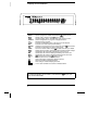
The Front Panel at a Glance Denotes a menu key. See the next page for details on menu operation.
The Front-Panel Menus at a Glance Several of the front-panel keys guide you through menus to configure various parameters of the instrument (see previous page). The following steps demonstrate the menu structure using the key. 1 Press the menu key. You are automatically guided to the first level of the menu. Rotate the knob to view the other choices on the first level of the menu. The menu will automatically timeout after about 20 seconds of inactivity.
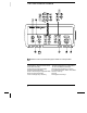
Display Annunciators SCAN MON VIEW CONFIG ADRS RMT ERROR EXT ONCE MEM LAST MIN MAX SHIFT 4W OC Scan is in progress or enabled. Press and hold again to turn off. Monitor mode is enabled. Press again to turn off. Scanned readings, alarms, errors, or relay cycles are being viewed. Channel configuration is in progress on displayed channel. Measurement is in progress. Instrument is addressed to listen or talk over the remote interface. Instrument is in remote mode (remote interface).
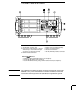
The Rear Panel at a Glance 1 Slot Identifier (100, 200, 300) 2 Ext Trig Input / Alarm Outputs / Channel Advance Input / Channel Closed Output (for pinouts, see pages 83 and 128) 3 RS-232 Interface Connector 4 5 6 7 Power-Line Fuse-Holder Assembly Power-Line Voltage Setting Chassis Ground Screw GP-IB (IEEE-488) Interface Connector Use the Menu to: • Select the GP-IB or RS-232 interface (see chapter 2). • Set the GP-IB address (see chapter 2).
BenchLink Data Logger Software at a Glance Agilent BenchLink Data Logger is a Windows-based application designed to make it easy to use the 34970A with your PC for gathering and analyzing measurements. Use the software to set up your test, acquire and archive measurement data, and perform real-time display and analysis of your incoming measurements. BenchLink Data Logger’s key functions include the following: • Configure measurements on the spreadsheet-like Scan Setup page.
The Plug-In Modules at a Glance For complete specifications on each plug-in module, refer to the module sections in chapter 9. 34901A 20-Channel Armature Multiplexer • 20 channels of 300 V switching • Two channels for DC or AC current measurements (100 nA to 1A) • Built-in thermocouple reference junction • Switching speed of up to 60 channels per second • Connects to the internal multimeter • For detailed information and a module diagram, see page 164.
34903A 20-Channel Actuator / General-Purpose Switch • 300 V, 1 A actuation and switching • SPDT (Form C) latching relays • Breadboard area for custom circuits • For detailed information and a module diagram, see page 168. Use this module for those applications that require high-integrity contacts or quality connections of non-multiplexed signals. This module can switch 300 V, 1 A (50 W maximum switch power) to your device under test or to actuate external devices.
34907A Multifunction Module • Two 8-bit Digital Input/Output ports, 400 mA sink, 42 V open collector • 100 kHz Totalize input with 1 Vpp sensitivity • Two ±12 V Calibrated Analog Outputs • For detailed information and module block diagrams, see page 174. Use this module to sense status and control external devices such as solenoids, power relays, and microwave switches. For greater flexibility, you can read digital inputs and the count on the totalizer during a scan.
In This Book Quick Start Chapter 1 helps you get familiar with a few of the instrument’s front-panel features. This chapter also shows how to install the BenchLink Data Logger software. Front-Panel Overview Chapter 2 introduces you to the front-panel menus and describes some of the instrument’s menu features. System Overview Chapter 3 gives an overview of a data acquisition system and describes how parts of a system work together.
Contents Chapter 1 Quick Start To Prepare the Instrument for Use 17 Installing BenchLink Data Logger Software 18 To Connect Wiring to a Module 20 To Set the Time and Date 22 To Configure a Channel for Scanning 23 To Copy a Channel Configuration 25 To Close a Channel 26 If the Instrument Does Not Turn On 27 To Adjust the Carrying Handle 29 To Rack Mount the Instrument 30 Chapter 2 Front-Panel Overview Contents Front-Panel Menu Reference 35 To Monitor a Single Channel 37 To Set a Scan Interval 38 To Apply
Contents Contents Chapter 4 Features and Functions SCPI Language Conventions 73 Scanning 74 Single-Channel Monitoring 93 Scanning With External Instruments 95 General Measurement Configuration 98 Temperature Measurement Configuration 106 Voltage Measurement Configuration 113 Resistance Measurement Configuration 115 Current Measurement Configuration 116 Frequency Measurement Configuration 118 Mx+B Scaling 119 Alarm Limits 122 Digital Input Operations 133 Totalizer Operations 135 Digital Output Operations 1
Contents Chapter 5 Remote Interface Reference Contents SCPI Command Summary 181 Simplified Programming Overview 201 The MEASure? and CONFigure Commands 207 Setting the Function, Range, and Resolution 214 Temperature Configuration Commands 219 Voltage Configuration Commands 223 Resistance Configuration Commands 224 Current Configuration Commands 224 Frequency Configuration Commands 225 Scanning Overview 226 Single-Channel Monitoring Overview 237 Scanning With an External Instrument 239 Mx+B Scaling Overvi
Contents Chapter 7 Application Programs Example Programs for Excel 7.
1 1 Quick Start
Quick Start One of the first things you will want to do with your instrument is to become acquainted with the front panel. We have written the exercises in this chapter to prepare the instrument for use and help you get familiar with some of its front-panel operations. The front panel has several groups of keys to select various functions and operations. A few keys have a shifted function printed in blue below the key. To perform a shifted function, press (the SHIFT annunciator will turn on).
Chapter 1 Quick Start To Prepare the Instrument for Use 1 To Prepare the Instrument for Use 1 Check the list of supplied items. Verify that you have received the following items with your instrument. If anything is missing, contact your nearest Agilent Technologies Sales Office. One power cord. This User’s Guide. One Service Guide. One Quick Reference Guide. Certificate of Calibration (if you ordered the internal DMM). Quick Start Package (if you ordered the internal DMM): • One RS-232 cable.
Chapter 1 Quick Start Installing BenchLink Data Logger Software Installing BenchLink Data Logger Software If you ordered the 34970A with the internal DMM, then the BenchLink Data Logger software is included. The software is shipped on one CD-ROM, but includes a utility to build installation floppy disks. To install the software on your PC, you will need a minimum of 12 MB of free disk space.
Chapter 1 Quick Start Installing BenchLink Data Logger Software 1 Creating Installation Floppy Disks You have the option to create an installation on floppy disks from the CD-ROM installation utility. This utility is provided so that you can install BenchLink Data Logger on a computer that does not have a CD-ROM drive. Note: You will need a total of five (5) formatted floppy disks to create an installation. 1. Go to a computer that is equipped with a CD-ROM drive. 2.
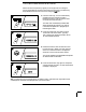
Chapter 1 Quick Start To Connect Wiring to a Module To Connect Wiring to a Module 1 Remove the module cover. 2 Connect wiring to the screw terminals. 20 AWG Typical 6 mm 3 Route wiring through strain relief. 4 Replace the module cover. Cable Tie Wrap (optional) 5 Install the module into mainframe. Channel Number: Slot Channel 20 Wiring Hints... • For detailed information on each module, refer to the section starting on page 163.
Chapter 1 Quick Start To Connect Wiring to a Module 1 Thermocouple Thermocouple Types: B, E, J, K, N, R, S, T See page 351 for thermocouple color codes. 2-Wire Ohms / RTD / Thermistor DC Voltage / AC Voltage / Frequency Ranges: 100 mV, 1 V, 10 V, 100 V, 300 V 4-Wire Ohms / RTD Ranges: 100, 1 k, 10 k, 100 k, 1 M, 10 M, 100 MΩ RTD Types: 0.00385, 0.00391 Thermistor Types: 2.
Chapter 1 Quick Start To Set the Time and Date To Set the Time and Date All readings during a scan are automatically time stamped and stored in non-volatile memory. In addition, alarm data is time stamped and stored in a separate non-volatile memory queue. 1 Set the time of day. Utility Use and to select the field to modify and turn the knob to change the value. You can also edit the AM/PM field. 7,0( 30 2 Set the date. Utility Use and the value.
Chapter 1 Quick Start To Configure a Channel for Scanning 1 To Configure a Channel for Scanning Any channel that can be “read” by the instrument can also be included in a scan. This includes readings on multiplexer channels, a read of a digital port, or a read of the count on a totalizer channel. Automated scanning is not allowed with the RF multiplexer, matrix, actuator, digital output, or voltage output (DAC) modules. 1 Select the channel to be added to the scan list.
Chapter 1 Quick Start To Configure a Channel for Scanning Note: Press to sequentially step through the scan list and take a measurement on each channel (readings are not stored in memory). This is an easy way to verify your wiring connections before initiating the scan. 3 Run the scan and store the readings in non-volatile memory. The instrument automatically scans the configured channels in consecutive order from slot 100 through slot 300 (the SCAN annunciator turns on).
Chapter 1 Quick Start To Copy a Channel Configuration 1 To Copy a Channel Configuration After configuring a channel to be included in the scan list, you can copy that same configuration to other channels in the instrument (including digital channels on the multifunction module). This feature makes it easy to configure several channels for the same measurement.
Chapter 1 Quick Start To Close a Channel To Close a Channel On the multiplexer and switch modules, you can close and open individual relays on the module. However, note that if you have already configured any multiplexer channels for scanning, you cannot independently close and open individual relays on that module. 1 Select the channel. Turn the knob until the desired channel is shown on the right side of front-panel display. For this example, select channel 213. 2 Close the selected channel.
Chapter 1 Quick Start If the Instrument Does Not Turn On 1 If the Instrument Does Not Turn On Use the following steps to help solve problems you might encounter when turning on the instrument. If you need more help, refer to the 34970A Service Guide for instructions on returning the instrument to Agilent for service. 1 Verify that there is ac power to the instrument. First, verify that the power cord is firmly plugged into the power receptacle on the rear panel of the instrument.
Chapter 1 Quick Start If the Instrument Does Not Turn On 1 Remove the power cord. Remove the fuse-holder assembly from the rear panel. 2 Remove the line-voltage selector from the assembly. Fuse: 500 mAT (for all line voltages) Agilent Part Number: 2110-0458 3 Rotate the line-voltage selector until the correct voltage appears in the window. 4 Replace the fuse-holder assembly in the rear panel.
Chapter 1 Quick Start To Adjust the Carrying Handle 1 To Adjust the Carrying Handle To adjust the position, grasp the handle by the sides and pull outward. Then, rotate the handle to the desired position.
Chapter 1 Quick Start To Rack Mount the Instrument To Rack Mount the Instrument You can mount the instrument in a standard 19-inch rack cabinet using one of three optional kits available. Instructions and mounting hardware are included with each rack-mounting kit. Any Agilent System II instrument of the same size can be rack-mounted beside the 34970A. Note: Remove the carrying handle, and the front and rear rubber bumpers, before rack-mounting the instrument.
Chapter 1 Quick Start To Rack Mount the Instrument 1 To rack mount a single instrument, order adapter kit 5063-9240. To rack mount two instruments side-by-side, order lock-link kit 5061-9694 and flange kit 5063-9212. Be sure to use the support rails inside the rack cabinet. To install one or two instruments in a sliding support shelf, order shelf 5063-9255, and slide kit 1494-0015 (for a single instrument, also order filler panel 5002-3999).
32
2 2 Front-Panel Overview
Front-Panel Overview This chapter introduces you to the front-panel keys and menu operation. This chapter does not give a detailed description of every front-panel key or menu operation. It does, however, give you a good overview of the front-panel menu and many front-panel operations. See chapter 4 “Features and Functions,” starting on page 71, for a complete discussion of the instrument’s capabilities and operation.
Chapter 2 Front-Panel Overview Front-Panel Menu Reference Front-Panel Menu Reference This section gives an overview of the front-panel menus. The menus are designed to automatically guide you through all parameters required to configure a particular function or operation. The remainder of this chapter shows examples of using the front-panel menus. Configure the measurement parameters on the displayed channel. • • • • • • Select measurement function (dc volts, ohms, etc.) on the displayed channel.
Chapter 2 Front-Panel Overview Front-Panel Menu Reference Configure the advanced measurement features on displayed channel. • • • • • • • • • Set the integration time for measurements on the displayed channel. Set the channel-to-channel delay for scanning. Enable/disable the thermocouple check feature (T/C measurements only). Select the reference junction source (T/C measurements only). Set the low frequency limit (ac measurements only). Enable/disable offset compensation (resistance measurements only).
Chapter 2 Front-Panel Overview To Monitor a Single Channel To Monitor a Single Channel You can use the Monitor function to continuously take readings on a single channel, even during a scan. This feature is useful for troubleshooting your system before a test or for watching an important signal. 1 Select the channel to be monitored. Only one channel can be monitored at a time but you can change the channel being monitored at any time by turning the knob. 2 Enable monitoring on the selected channel.
Chapter 2 Front-Panel Overview To Set a Scan Interval To Set a Scan Interval You can set the instrument’s internal timer to automatically scan at a specific interval (e.g., start a new scan sweep every 10 seconds) or when an external TTL trigger pulse is received. You can configure the instrument to scan continuously or to stop after sweeping through the scan list a specified number of times. 1 Select the interval scan mode.
Chapter 2 Front-Panel Overview To Apply Mx+B Scaling to Measurements To Apply Mx+B Scaling to Measurements The scaling function allows you to apply a gain and offset to all readings on a specified multiplexer channel during a scan. In addition to setting the gain (“M”) and offset (“B”) values, you can also specify a custom measurement label for your scaled readings (RPM, PSI, etc.). 1 Configure the channel. You must configure the channel (function, transducer type, etc.) before applying any scaling values.
Chapter 2 Front-Panel Overview To Configure Alarm Limits To Configure Alarm Limits The instrument has four alarms which you can configure to alert you when a reading exceeds specified limits on a channel during a scan. You can assign a high limit, a low limit, or both to any configured channel in the scan list. You can assign multiple channels to any of the four available alarms (numbered 1 through 4). 1 Configure the channel. You must configure the channel (function, transducer type, etc.
Chapter 2 Front-Panel Overview To Configure Alarm Limits 4 Set the limit value. The alarm limit values are stored in non-volatile memory for the specified channels. The default values for the high and low limits are “0”. The low limit must always be less than or equal to the high limit, even if you are using only one of the limits. A Factory Reset clears all alarm limits and turns off all alarms. An Instrument Preset or Card Reset does not clear the alarm limits and does not turn off alarms.
Chapter 2 Front-Panel Overview To Read a Digital Input Port To Read a Digital Input Port The multifunction module (34907A) has two non-isolated 8-bit input/output ports which you can use for reading digital patterns. You can read the live status of the bits on the port or you can configure a scan to include a digital read. 1 Select the Digital Input port. Select the slot containing the multifunction module and continue turning the knob until DIN is displayed (channel 01 or 02). 2 Read the specified port.
Chapter 2 Front-Panel Overview To Write to a Digital Output Port To Write to a Digital Output Port The multifunction module (34907A) has two non-isolated 8-bit input/output ports which you can use for outputting digital patterns. 2 1 Select the Digital Output port. Select the slot containing the multifunction module and continue turning the knob until DIN is displayed (channel 01 or 02). 2 Enter the bit pattern editor. Notice that the port is now converted to an output port (DOUT).
Chapter 2 Front-Panel Overview To Read the Totalizer Count To Read the Totalizer Count The multifunction module (34907A) has a 26-bit totalizer which can count pulses at a 100 kHz rate. You can manually read the totalizer count or you can configure a scan to read the count. 1 Select the totalizer channel. Select the slot containing the multifunction module and continue turning the knob until TOTALIZE is displayed (channel 03). 2 Configure the totalize mode.
Chapter 2 Front-Panel Overview To Output a DC Voltage To Output a DC Voltage The multifunction module (34907A) has two analog outputs capable of outputting calibrated voltages between ±12 volts. 2 1 Select a DAC Output channel. Select the slot containing the multifunction module and continue turning the knob until DAC is displayed (channel 04 or 05). 2 Enter the output voltage editor. 9 '$& 3 Set the desired output voltage. Use the knob and or keys to edit the individual digits.
Chapter 2 Front-Panel Overview To Configure the Remote Interface To Configure the Remote Interface The instrument is shipped with both an GPIB (IEEE-488) interface and an RS-232 interface. Only one interface can be enabled at a time. The GPIB interface is selected when the instrument is shipped from the factory. GPIB Configuration 1 Select the GPIB (HPIB) interface. +3,% 2 Select the GPIB address. Interface You can set the instrument’s address to any value between 0 and 30.
Chapter 2 Front-Panel Overview To Configure the Remote Interface RS-232 Configuration 1 Select the RS-232 interface. 2 56 2 Select the baud rate. Interface Select one of the following: 1200, 2400, 4800, 9600, 19200, 38400, 57600 (factory setting), or 115200 baud. %$8' 3 Select the parity and number of data bits. Interface Select one of the following: None (8 data bits, factory setting), Even (7 data bits), or Odd (7 data bits).
Chapter 2 Front-Panel Overview To Store the Instrument State To Store the Instrument State You can store the instrument state in one of five non-volatile storage locations. A sixth storage location automatically holds the power-down configuration of the instrument. When power is restored, the instrument can automatically return to its state before power-down (a scan in progress before power-down will also be resumed). 1 Select the storage location.
3 3 System Overview
System Overview This chapter provides an overview of a computer-based system and describes the parts of a data acquisition system.
Chapter 3 System Overview Data Acquisition System Overview The system configuration shown on the previous page offers the following advantages: • You can use the 34970A to perform data storage, data reduction, mathematical calculations, and conversion to engineering units. You can use the PC to provide easy configuration and data presentation. • You can remove the analog signals and measurement sensors from the noisy PC environment and electrically isolate them from both the PC and earth ground.
Chapter 3 System Overview Data Acquisition System Overview Measurement Software A variety of software is available to configure your data acquisition hardware and manipulate and display your measurement data. Data Logging and Monitoring Agilent BenchLink Data Logger is a Windows®-based application designed to make it easy to use the 34970A with your PC for gathering and analyzing measurements. The software is included with the 34970A when you order the internal DMM.
Chapter 3 System Overview Data Acquisition System Overview The 34970A Data Acquisition / Switch Unit As shown below, the logic circuitry for the 34970A is divided into two sections: earth-referenced and floating. These two sections are isolated from each other in order to maintain measurement accuracy and repeatability (for more information on ground loops, see page 341).
Chapter 3 System Overview Data Acquisition System Overview Plug-In Modules The 34970A offers a complete selection of plug-in modules to give you high-quality measurement, switching, and control capabilities. The plug-in modules communicate with the floating logic via the internal isolated digital bus. The multiplexer modules also connect to the internal DMM via the internal analog bus.
Chapter 3 System Overview Data Acquisition System Overview System Cabling The plug-in modules have screw-terminal connectors to make it easy to connect your system cabling. The type of cabling that you use to connect your signals, transducers, and sensors to the module is critical to measurement success. Some types of transducers, such as thermocouples, have very specific requirements for the type of cable that can be used to make connections.
Chapter 3 System Overview Data Acquisition System Overview Transducers and Sensors Transducers and sensors convert a physical quantity into an electrical quantity. The electrical quantity is measured and the result is then converted to engineering units. For example, when measuring a thermocouple, the instrument measures a dc voltage and mathematically converts it to a corresponding temperature in °C, °F, or K.
Chapter 3 System Overview Signal Routing and Switching Signal Routing and Switching The switching capabilities of the plug-in modules available with the 34970A provide test system flexibility and expandability. You can use the switching plug-in modules to route signals to and from your test system or multiplex signals to the internal DMM or external instruments. Relays are electromechanical devices which are subject to wear-out failure modes.
Chapter 3 System Overview Signal Routing and Switching Multiplexer Switching Multiplexers allow you to connect one of multiple channels to a common channel, one at a time. A simple 4-to-1 multiplexer is shown below. When you combine a multiplexer with a measurement device, like the internal DMM, you create a scanner. For more information on scanning, see page 62.
Chapter 3 System Overview Signal Routing and Switching Matrix Switching A matrix switch connects multiple inputs to multiple outputs and therefore offers more switching flexibility than a multiplexer. Use a matrix for switching low-frequency (less than 10 MHz) signals only. A matrix is arranged in rows and columns. For example, a simple 3x3 matrix could be used to connect three sources to three test points as shown below.
Chapter 3 System Overview Measurement Input Measurement Input The 34970A allows you to combine a DMM (either internal or external) with multiplexer channels to create a scan. During a scan, the instrument connects the DMM to the configured multiplexer channels one at a time and makes a measurement on each channel. Any channel that can be “read” by the instrument can also be included in a scan.
Chapter 3 System Overview Measurement Input Signal Conditioning, Ranging, and Amplification Analog input signals are multiplexed into the internal DMM’s signal-conditioning section – typically comprising switching, ranging, and amplification circuitry. If the input signal is a dc voltage, the signal conditioner is composed of an attenuator for the higher input voltages and a dc amplifier for the lower input voltages.
Chapter 3 System Overview Measurement Input Main Processor The main processor, located in the floating logic section, controls the input signal conditioning, ranging, and the ADC. The main processor accepts commands from, and sends measurement results to, the earth-referenced logic section. The main processor synchronizes measurements during scanning and control operations. The main processor uses a multi-tasking operating system to manage the various system resources and demands.
Chapter 3 System Overview Measurement Input You can configure the event or action that controls the onset of each sweep through the scan list (a sweep is one pass through the scan list): • You can set the instrument’s internal timer to automatically scan at a specific interval as shown below. You can also program a time delay between channels in the scan list.
Chapter 3 System Overview Measurement Input Scanning With External Instruments If your application doesn’t require the built-in measurement capabilities of the 34970A, you can order it without the internal DMM. In this configuration, you can use the 34970A for signal routing or control applications. If you install a multiplexer plug-in module, you can use the 34970A for scanning with an external instrument. You can connect an external instrument (such as a DMM) to the multiplexer COM terminal.
Chapter 3 System Overview Measurement Input The Multifunction Module The multifunction module (34907A) adds two additional measurement input capabilities to the system: digital input and event totalize. The multifunction module also contains a dual voltage output (DAC) which is described in more detail on page 68. Digital Input The multifunction module has two non-isolated 8-bit input/output ports which you can use for reading digital patterns.
Chapter 3 System Overview Measurement Input Totalizer The multifunction module has a 26-bit totalizer which can count pulses at a 100 kHz rate. You can manually read the totalizer count or you can configure a scan to read the count. +IN -IN 26 Bits Channel 03 Totalize Gate Gate • You can configure the totalizer to count on the rising edge or falling edge of the input signal. • The maximum count is 67,108,863 (226- 1). The count rolls over to “0” after reaching the maximum allowed value.
Chapter 3 System Overview Control Output Control Output In addition to signal routing and measurement, you can also use the 34970A to provide simple control outputs. For example, you can control external high-power relays using the actuator module or a digital output channel. The Multifunction Module 3 The multifunction module (34907A) adds two additional control output capabilities to the system: digital output and voltage (DAC) output.
Chapter 3 System Overview Control Output Voltage (DAC) Output The multifunction module has two analog outputs capable of outputting calibrated voltages between ±12 volts with 16 bits of resolution. Each DAC (Digital-to-Analog Converter) channel can be used as a programmable voltage source for analog input control of other devices. A simplified diagram is shown below. 16 DAC 1 Channel 04 DAC 2 Channel 05 16 • You can set the output voltage to any value between +12 Vdc and -12 Vdc, in 1 mV steps.
Chapter 3 System Overview Control Output The Actuator / General-Purpose Switch You can think of the 34903A Actuator as a control output because it is often used to control external power devices. The actuator provides 20 independent, isolated Form C (SPDT) switches. Channel Open (NC Contact Connected) NO = Normally Open NC = Normally Closed Channel Closed (NO Contact Connected) NO NO NC NC COM COM 3 Each channel can switch up to 300V dc or ac rms.
70
4 4 Features and Functions
Features and Functions You will find that this chapter makes it easy to look up all the details about a particular feature of the 34970A. Whether you are operating the instrument from the front panel or over the remote interface, this chapter will be useful.
Chapter 4 Features and Functions SCPI Language Conventions SCPI Language Conventions Throughout this manual, the following conventions are used for SCPI command syntax for remote interface programming: • Square brackets ( [ ] ) indicate optional keywords or parameters. • Braces ( { } ) enclose parameter choices within a command string. • Triangle brackets ( < > ) enclose parameters for which you must substitute a value. • A vertical bar ( | ) separates multiple parameter choices.
Chapter 4 Features and Functions Scanning Scanning The instrument allows you to combine a DMM (either internal or external) with multiplexer channels to create a scan. During a scan, the instrument connects the DMM to the configured multiplexer channels one at a time and makes a measurement on each channel. Any channel that can be “read” by the instrument can also be included in a scan.
Chapter 4 Features and Functions Scanning • Each time you start a new scan, the instrument clears all readings (including alarm data) stored in reading memory from the previous scan. Therefore, the contents of memory are always from the most recent scan. • While a scan is running, the instrument automatically stores the minimum and maximum readings and calculates the average for each channel. You can read these values at any time, even during a scan.
Chapter 4 Features and Functions Scanning • When you add a digital read (multifunction module) to a scan list, that port is dedicated to the scan. The instrument issues a Card Reset to make that port an input port (the other port is not affected). • While a scan is running, you can perform low-level control operations on any channels on the multifunction module that are not in the scan. For example, you can output a DAC voltage or write to a digital port (even if the totalizer is part of the scan list).
Chapter 4 Features and Functions Scanning Power Failure • When shipped from the factory, the instrument is configured to automatically recall the power-down state when power is restored. In this configuration, the instrument will automatically recall the instrument state at power-down and resume a scan in progress.
Chapter 4 Features and Functions Scanning Adding Channels to a Scan List Before you can initiate a scan, you must configure the channels to be scanned and set up a scan list (these two operations occur simultaneously from the front panel). The instrument automatically scans the configured channels in ascending order from slot 100 through slot 300. To Build a Scan List From the Front Panel: To add the active channel to the scan list, press .
Chapter 4 Features and Functions Scanning To Build a Scan List From the Remote Interface: • The MEASure?, CONFigure, and ROUTe:SCAN commands contain a scan_list parameter which defines the list of channels in the scan list. Note that each time you send one of these commands, it redefines the scan list. To determine which channels are currently in the scan list, you can send the ROUTe:SCAN? query command. • To initiate a scan, execute the MEASure?, READ?, or INITiate command.
Chapter 4 Features and Functions Scanning Scan Interval You can configure the event or action that controls the onset of each sweep through the scan list (a sweep is one pass through the scan list): • You can set the instrument’s internal timer to automatically scan at a specific interval. You can also program a time delay between channels in the scan list. • You can manually control a scan by repeatedly pressing the front panel.
Chapter 4 Features and Functions Scanning • You can set the scan interval to any value between 0 seconds and 99:59:59 hours (359,999 seconds), with 1 ms resolution. • Once you have initiated the scan, the instrument will continue scanning until you stop it or until the scan count is reached. See “Scan Count” on page 86 for more information. • Mx+B scaling and alarm limits are applied to measurements during a scan and all data is stored in non-volatile memory.
Chapter 4 Features and Functions Scanning Scan Once In this configuration, the instrument waits for either a front-panel key press or a remote interface command before sweeping through the scan list. • All readings from the scan are stored in non-volatile memory. Readings accumulate in memory until the scan is terminated (until the scan count is reached or until you abort the scan).
Chapter 4 Features and Functions Scanning External Scanning In this configuration, the instrument sweeps through the scan list once each time a low-going TTL pulse is received on the rear-panel Ext Trig Input line (pin 6). Input 5V 0V Ext Trig Input Gnd > 1 µs Ext Trig Connector • You can specify a scan count which sets the number of external pulses the instrument will accept before terminating the scan. See “Scan Count” on page 86 for more information.
Chapter 4 Features and Functions Scanning Scanning on Alarm In this configuration, the instrument sweeps the scan list once each time a reading crossing an alarm limit on a channel. You can also assign alarms to channels on the multifunction module. For example, you can generate an alarm when a specific bit pattern is detected or when a specific count is reached. Note: For complete details on configuring and using alarms, refer to “Alarm Limits” starting on page 122.
Chapter 4 Features and Functions Scanning • Remote Interface Operation: The following program segment configures the instrument to scan when an alarm occurs.
Chapter 4 Features and Functions Scanning Scan Count You can specify the number of times the instrument will sweep through the scan list. When the specified number of sweeps have occurred, the scan stops. • Select a scan count between 1 to 50,000 scan sweeps, or continuous. • During an Interval Scan (see page 80), the scan count sets the number of times the instrument will sweep through the scan list and therefore determines the overall duration of the scan.
Chapter 4 Features and Functions Scanning Reading Format During a scan, the instrument automatically adds a time stamp to all readings and stores them in non-volatile memory. Each reading is stored with measurement units, time stamp, channel number, and alarm status information. From the remote interface, you can specify which information you want returned with the readings (from the front panel, all of the information is available for viewing).
Chapter 4 Features and Functions Scanning Channel Delay You can control the pace of a scan sweep by inserting a delay between multiplexer channels in the scan list (useful for high-impedance or high-capacitance circuits). The delay is inserted between the relay closure and the actual measurement on the channel. The programmed channel delay overrides the default channel delay that the instrument automatically adds to each channel.
Chapter 4 Features and Functions Scanning Automatic Channel Delays If you do not specify a channel delay, the instrument selects a delay for you. The delay is determined by function, range, integration time, and ac filter setting as shown below. DC Voltage, Thermocouple, DC Current (for all ranges): Integration Time PLC > 1 PLC ≤ 1 Channel Delay 2.0 ms 1.
Chapter 4 Features and Functions Scanning • Front-Panel Operation: CH DELAY AUTO • Remote Interface Operation: The following command enables an automatic channel delay on channel 01. ROUT:CHAN:DELAY:AUTO ON,(@101) Selecting a specific channel delay using the ROUTe:CHANnel:DELay command disables the automatic channel delay. Viewing Readings Stored in Memory During a scan, the instrument automatically adds a time stamp to all readings and stores them in non-volatile memory.
Chapter 4 Features and Functions Scanning • Readings acquired during a Monitor are not stored in memory (however, all readings from a scan in progress at the same time are stored in memory). • The MEASure? and READ? commands send readings directly to the instrument’s output buffer but readings are not stored in memory. You will not be able to view these readings. • The INITiate command stores readings in memory.
Chapter 4 Features and Functions Scanning • Remote Interface Operation: The following command retrieves stored readings from memory (the readings are not erased). FETCH? Use the following commands to query the statistics on the readings stored in memory for a specific channel. These commands do not remove the data from memory.
Chapter 4 Features and Functions Single-Channel Monitoring Single-Channel Monitoring In the Monitor function, the instrument takes readings as often as it can on a single channel, even during a scan. This feature is useful for troubleshooting your system before a test or for watching an important signal. Any channel that can be “read” by the instrument can be monitored. This includes any combination of temperature, voltage, resistance, current, frequency, or period measurements on multiplexer channels.
Chapter 4 Features and Functions Single-Channel Monitoring • In the Alarm Scan configuration (see “Scanning on Alarm” on page 84), the instrument sweeps the scan list once each time a reading crosses an alarm limit on a channel. In this configuration, you may use the Monitor function to continuously take readings on a selected channel and wait for an alarm on that channel.
Chapter 4 Features and Functions Scanning With External Instruments Scanning With External Instruments If your application doesn’t require the built-in measurement capabilities of the 34970A, you can order it without the internal DMM. In this configuration, you can use the system for signal routing or control applications. If you install a multiplexer plug-in module, you can use the system for scanning with an external instrument.
Chapter 4 Features and Functions Scanning With External Instruments In this configuration, you must set up a scan list to include all desired multiplexer or digital channels. Channels which are not in the list are skipped during the scan. The instrument automatically scans the list of channels in ascending order from slot 100 through slot 300. For an externally-controlled scan, you must either remove the internal DMM from the 34970A or disable it (see “Internal DMM Disable” on page 145).
Chapter 4 Features and Functions Scanning With External Instruments • An externally-controlled scan can also include a read of a digital port or a read of the totalizer count on the multifunction module. When the channel advance reaches the first digital channel, the instrument scans through all of the digital channels in that slot and stores the readings in reading memory (only one channel advance signal is required).
Chapter 4 Features and Functions General Measurement Configuration General Measurement Configuration This section contains general information to help you configure the instrument for making measurements during a scan. Since these parameters are used by several measurement functions, the discussion is combined into one common section. Refer to the later sections in this chapter for more information on parameters that are specific to a particular measurement function.
Chapter 4 Features and Functions General Measurement Configuration • For frequency and period measurements, the instrument uses one “range” for all inputs between 3 Hz and 300 kHz. The range parameter is required only to specify the resolution. Therefore, it is not necessary to send a new command for each new frequency to be measured. • The MEASure? and CONFigure commands contain an optional range parameter which allows you to specify the range or autoranging.
Chapter 4 Features and Functions General Measurement Configuration Measurement Resolution Resolution is expressed in terms of number of digits the instrument can measure or display on the front panel. You can set the resolution to 4, 5, or 6 full digits, plus a “1⁄2” digit which can only be a “0” or “1”. To increase your measurement accuracy and improve noise rejection, select 61⁄2 digits. To increase your measurement speed, select 41⁄2 digits.
Chapter 4 Features and Functions General Measurement Configuration • The specified resolution is used for all measurements on the selected channel. If you have applied Mx+B scaling or have assigned alarms to the selected channel, those measurements are also made using the specified resolution. Measurements taken during the Monitor function also use the specified resolution. • Changing the number of digits does more than just change the resolution of the instrument.
Chapter 4 Features and Functions General Measurement Configuration • Remote Interface Operation: Specify the resolution in the same units as the measurement function, not in number of digits. For example, if the function is dc volts, specify the resolution in volts. For frequency, specify the resolution in hertz. You can select the resolution using parameters in the MEASure? and CONFigure commands. For example, the following statement selects the 10 Vdc range with 41⁄2 digits of resolution on channel 301.
Chapter 4 Features and Functions General Measurement Configuration Custom A/D Integration Time Integration time is the period of time that the instrument’s analog-todigital (A/D ) converter samples the input signal for a measurement. Integration time affects the measurement resolution (for better resolution, use a longer integration time) and measurement speed (for faster measurements, use a shorter integration time). • Integration time is specified in number of power line cycles (PLCs). Select from 0.
Chapter 4 Features and Functions General Measurement Configuration • The instrument selects 1 PLC when the measurement function is changed and after a Factory Reset (*RST command). An Instrument Preset (SYSTem:PRESet command) or Card Reset (SYSTem:CPON command) does not change the integration time setting. • Front-Panel Operation: First, select the measurement function on the active channel. Then, go to the Advanced menu and select one of the choices in PLCs for the active channel.
Chapter 4 Features and Functions General Measurement Configuration Autozero When autozero is enabled (default), the instrument internally disconnects the input signal following each measurement, and takes a zero reading. It then subtracts the zero reading from the preceding reading. This prevents offset voltages present on the instrument’s input circuitry from affecting measurement accuracy. When autozero is disabled, the instrument takes one zero reading and subtracts it from all subsequent measurements.
Chapter 4 Features and Functions Temperature Measurement Configuration Temperature Measurement Configuration This section contains information to help you configure the instrument for making temperature measurements. For more information on the types of temperature transducers, see “Temperature Measurements” starting on page 345 in chapter 8. The instrument supports direct measurement of thermocouples, RTDs, and thermistors.
Chapter 4 Features and Functions Temperature Measurement Configuration Thermocouple Measurements To connect a thermocouple to the module’s screw terminals, see page 21. • The instrument supports the following thermocouple types: B, E, J, K, N, R, S, and T using ITS-90 software conversions. The default is a J-Type thermocouple. • Thermocouple measurements require a reference junction temperature.
Chapter 4 Features and Functions Temperature Measurement Configuration • Front-Panel Operation: To select the thermocouple function on the active channel, choose the following items. TEMPERATURE , THERMOCOUPLE To select the thermocouple type for the active channel, choose the following item. J TYPE T/C To enable the thermocouple check feature on the active channel (opens are reported as “OPEN T/C”), choose the following item.
Chapter 4 Features and Functions Temperature Measurement Configuration • Remote Interface Operation: You can use the MEASure? or CONFigure command to select the probe type and thermocouple type. For example, the following statement configures channel 301 for a J-type thermocouple measurement. CONF:TEMP TC,J,(@301) You can also use the SENSe command to select the probe type and thermocouple type. For example, the following statement configures channel 203 for a J-type thermocouple measurement.
Chapter 4 Features and Functions Temperature Measurement Configuration RTD Measurements To connect an RTD to the module’s screw terminals, see page 21. • The instrument supports RTDs with α = 0.00385 (DIN / IEC 751) using ITS-90 software conversions or α = 0.00391 using IPTS-68 software conversions. The default is α = 0.00385. • The resistance of an RTD is nominal at 0 °C and is referred to as R0. The instrument can measure RTDs with R0 values from 49Ω to 2.1 kΩ. The default is R0 = 100Ω.
Chapter 4 Features and Functions Temperature Measurement Configuration • Remote Interface Operation: You can use the MEASure? or CONFigure command to select the probe type and RTD type. For example, the following statement configures channel 301 for 2-wire measurements of an RTD with α = 0.00385 (use “85” to specify α = 0.00385 or “91” to specify α = 0.00391). CONF:TEMP RTD,85,(@301) You can also use the SENSe command to select the probe type, RTD type, and nominal resistance.
Chapter 4 Features and Functions Temperature Measurement Configuration Thermistor Measurements To connect a thermistor to the module’s screw terminals, see page 21. • The instrument supports 2.2 kΩ (44004), 5 kΩ (44007), and 10 kΩ (44006) thermistors. • Front-Panel Operation: To select the thermistor function for the active channel, choose the following items. TEMPERATURE , THERMISTOR To select the thermistor type for the active channel, choose from the following items. TYPE 2.
Chapter 4 Features and Functions Voltage Measurement Configuration Voltage Measurement Configuration To connect voltage sources to the module’s screw terminals, see page 21. This section contains information to help you configure the instrument for making voltage measurements. The instrument can measure dc and true RMS ac-coupled voltages on the measurement ranges shown below.
Chapter 4 Features and Functions Voltage Measurement Configuration • Remote Interface Operation: You can enable or disable the automatic input resistance mode on the specified channels. With AUTO OFF (default), the input resistance is fixed at 10 MΩ for all ranges. With AUTO ON, the input resistance is set to >10 GΩ for the three lowest dc voltage ranges. The MEASure? and CONFigure commands automatically select AUTO OFF.
Chapter 4 Features and Functions Resistance Measurement Configuration Resistance Measurement Configuration To connect resistances to the module’s screw terminals, see page 21. This section contains information to help you configure the instrument for making resistance measurements. Use the 2-wire method for ease of wiring and higher density or the 4-wire method for improved measurement accuracy. The measurement ranges are shown below.
Chapter 4 Features and Functions Current Measurement Configuration Current Measurement Configuration To connect a current source to the module’s screw terminals, see page 21. This section contains information to help you configure the instrument for making current measurements on the 34901A multiplexer module. This module has two fused channels for direct dc and ac current measurements on the measurement ranges shown below.
Chapter 4 Features and Functions Current Measurement Configuration • Front-Panel Operation: First, select the ac current (or ac voltage) function on the active channel. Then, go to the Advanced menu and select the slow filter (3 Hz), medium filter (20 Hz), or fast filter (200 Hz) for the active channel. The default is the medium filter. LF 3 HZ:SLOW • Remote Interface Operation: Specify the lowest frequency expected in the input signal on the specified channels.
Chapter 4 Features and Functions Frequency Measurement Configuration Frequency Measurement Configuration To connect an ac source to the module’s screw terminals, see page 21. Low Frequency Timeout The instrument uses three different timeout ranges for frequency measurements. The instrument selects a slow, medium, or fast timeout based on the input frequency that you specify for the selected channels.
Chapter 4 Features and Functions Mx+B Scaling Mx+B Scaling The scaling function allows you to apply a gain and offset to all readings on a specified multiplexer channel during a scan. In addition to setting the gain (“M”) and offset (“B”) values, you can also specify a custom measurement label for your scaled readings (RPM, PSI, etc.). You can apply scaling to any multiplexer channels and for any measurement function. Scaling is not allowed with any of the digital channels on the multifunction module.
Chapter 4 Features and Functions Mx+B Scaling • During a Monitor operation, the gain and offset values are applied to all readings on the specified channel. • You can specify a custom label with up to three characters. You can use letters (A-Z), numbers (0-9), an underscore ( _ ), or the “#” character which displays a degree symbol ( ° ) on the front panel (displayed as a blank space in an output string from the remote interface).
Chapter 4 Features and Functions Mx+B Scaling • Front-Panel Operation: The menu automatically guides you through the gain, offset, and measurement label settings. SET GAIN , SET OFFSET , SET LABEL To reset the gain, offset, and measurement label to their defaults, go to the corresponding level in the menu and turn the knob. To turn scaling off (without clearing the gain and offset values), go to the first level in the menu and select SCALING OFF.
Chapter 4 Features and Functions Alarm Limits Alarm Limits The instrument has four alarms which you can configure to alert you when a reading exceeds specified limits on a channel during a scan. You can assign a high limit, a low limit, or both to any configured channel in the scan list. You can assign multiple channels to any of the four available alarms (numbered 1 through 4).
Chapter 4 Features and Functions Alarm Limits • You can assign an alarm to any configured channel and multiple channels can be assigned to the same alarm number. However, you cannot assign alarms on a specific channel to more than one alarm number. • When an alarm occurs, the instrument stores relevant information about the alarm in the queue. This includes the reading that caused the alarm, the time of day and date of the alarm, and the channel number on which the alarm occurred.
Chapter 4 Features and Functions Alarm Limits • Alarms are logged in the alarm queue only when a reading crosses a limit, not while it remains outside the limit and not when it returns to within limits. Alarm Event No Alarm Upper Limit Lower Limit • Four TTL alarm outputs are available on the rear-panel Alarms connector. You can use these hardware outputs to trigger external alarm lights, sirens, or send a TTL pulse to your control system.
Chapter 4 Features and Functions Alarm Limits • For details on configuring alarms on the multifunction module, see “Using Alarms With the Multifunction Module” on page 130. • A Factory Reset (*RST command) clears all alarm limits and turns off all alarms. An Instrument Preset (SYSTem:PRESet command) or Card Reset (SYSTem:CPON command) does not clear the alarm limits and does not turn off alarms. • Front-Panel Operation: To select the alarm for use on the active channel, choose from the following items.
Chapter 4 Features and Functions Alarm Limits Viewing Stored Alarm Data If an alarm occurs on a channel as it is being scanned, then that channel’s alarm status is stored in reading memory as the readings are taken. As alarm events are generated, they are also logged in an alarm queue, which is separate from reading memory. This is the only place where non-scanned alarms get logged (alarms during a monitor, alarms generated by the multifunction module, etc.).
Chapter 4 Features and Functions Alarm Limits • Remote Interface Operation: The following command reads data from the alarm queue (one alarm event is read and cleared each time this command is executed). SYSTEM:ALARM? The following is an example of an alarm stored in the alarm queue (if no alarm data is in the queue, the command returns “0” for each field). 1 Reading with Units (31.009 °C) 2 Date (May 1, 1997) 3 Time (2:39:40.
Chapter 4 Features and Functions Alarm Limits Using the Alarm Output Lines Four TTL alarm outputs are available on the rear-panel Alarms connector. You can use these hardware outputs to trigger external alarm lights, sirens, or send a TTL pulse to your control system. You can assign an alarm to any configured channel and multiple channels can be assigned to the same alarm number.
Chapter 4 Features and Functions Alarm Limits • You can control the slope of the pulse from the alarm outputs (the selected configuration is used for all four outputs). In the falling edge mode, 0V (TTL low) indicates an alarm. In the rising edge mode, +5V (TTL high) indicates an alarm. A Factory Reset (*RST command) will reset the slope to falling edge. Falling Edge Rising Edge Note: Changing the slope of the output lines may cause the lines to change state.
Chapter 4 Features and Functions Alarm Limits Using Alarms With the Multifunction Module You can configure the instrument to generate an alarm when a specific bit pattern or bit pattern change is detected on a digital input channel or when a specific count is reached on a totalizer channel. These channels do not have to be part of the scan list to generate an alarm. Alarms are evaluated continuously as soon as you enable them.
Chapter 4 Features and Functions Alarm Limits • Remote Interface Operation (Digital Input Channel): To assign the alarm number to report any alarm conditions on the specified digital input channels, use the following command. OUTPut:ALARm[1|2|3|4]:SOURce (@) To configure alarms on the specified digital input channel, use the following commands (also see the example on the following page).
Chapter 4 Features and Functions Alarm Limits Example: Configuring an Alarm on a Digital Input Assume that you want to generate an alarm when a binary pattern of “1000” is read on the upper four bits of port 1. Send the following commands to configure the port for an alarm.
Chapter 4 Features and Functions Digital Input Operations Digital Input Operations The multifunction module (34907A) has two non-isolated 8-bit input/output ports which you can use for reading digital patterns. You can read the live status of the bits on the port or you can configure a scan to include a digital read. • The digital input channels are numbered “s01” (lower byte) and “s02” (upper byte), where s represents the slot number.
Chapter 4 Features and Functions Digital Input Operations • Front-Panel Operation: After selecting the port, press to read the bit pattern (the least significant bit is on the right). The bit pattern read from the port will be displayed until you press another key, turn the knob, or until the display times out. To add a digital read to a scan list, choose the following item. DIO READ From the front-panel only, you can specify whether you want to use binary or decimal format.
Chapter 4 Features and Functions Totalizer Operations Totalizer Operations The multifunction module has a 26-bit totalizer which can count TTL pulses at a 100 kHz rate. You can manually read the totalizer count or you can configure a scan to read the count. • The totalizer channel is numbered “s03”, where s represents the slot number. • You can configure the instrument to count on the rising edge or falling edge of the input signal.
Chapter 4 Features and Functions Totalizer Operations • The maximum count is 67,108,863 (226-1). The count rolls over to “0” after reaching the maximum allowed value. • You can configure the totalizer to reset its count after it is read without losing any counts (TOTalize:TYPE RRESet command). Then, if the totalizer is included in a scan list, the count will be reset on every scan sweep.
Chapter 4 Features and Functions Totalizer Operations • Remote Interface Operation: To read the count from the specified totalizer channel, send the following command. The count may be returned with time stamp, channel number, and alarm status information depending on the FORMat:READing command setting (see “Reading Format” on page 87 for more information). SENS:TOT:DATA? (@303) To configure the totalizer reset mode, send either of the following commands (RRESet means “read and reset”).
Chapter 4 Features and Functions Digital Output Operations Digital Output Operations The multifunction module (34907A) has two non-isolated 8-bit input/output ports which you can use for outputting digital patterns. • The digital output channels are numbered “s01” (lower byte) and “s02” (upper byte), where s represents the slot number. • You cannot configure a port for output operations if that port is already configured to be part of the scan list (digital input).
Chapter 4 Features and Functions DAC Output Operations DAC Output Operations The multifunction module (34907A) has two low-noise analog outputs capable of outputting calibrated voltages between ±12 volts with 16 bits of resolution. Each DAC (Digital-to-Analog Converter) channel can be used as a programmable voltage source for analog input control of other devices. • On the multifunction module, the DAC channels are numbered “s04” and “s05”, where s represents the slot number.
Chapter 4 Features and Functions System-Related Operations System-Related Operations This section gives information on system-related topics such as storing instrument states, reading errors, running a self-test, displaying messages on the front panel, setting the system clock, disabling the internal DMM, reading the firmware revisions, and reading the relay cycle count. State Storage The instrument has six storage locations in non-volatile memory to store instrument states.
Chapter 4 Features and Functions System-Related Operations • The name can contain up to 12 characters. The first character must be a letter (A-Z), but the remaining 11 characters can be letters, numbers (0-9), or the underscore character (“ _ ”). Blank spaces are not allowed. An error is generated if you specify a name with more than 12 characters. • A Factory Reset (*RST command) does not affect the configurations stored in memory.
Chapter 4 Features and Functions System-Related Operations Error Conditions When the front-panel ERROR annunciator turns on, one or more command syntax or hardware errors have been detected. A record of up to 10 errors is stored in the instrument’s error queue. See chapter 6 for a complete listing of the errors. • Errors are retrieved in first-in-first-out (FIFO) order. The first error returned is the first error that was stored. Errors are cleared as you read them.
Chapter 4 Features and Functions System-Related Operations Self-Test A power-on self-test occurs automatically when you turn on the instrument. This limited test assures you that the instrument and all installed plug-in modules are operational. This self-test does not perform the extensive set of tests that are included as part of the complete self-test described below. A complete self-test runs a series of tests and takes approximately 20 seconds to execute.
Chapter 4 Features and Functions System-Related Operations Display Control For security reasons or for a slight increase in scanning rates, you may want to turn off the front-panel display. From the remote interface, you can also display a 13-character message on the front-display. • You can only disable the front-panel display by sending a command from the remote interface (you cannot disable the front panel while in local operation).
Chapter 4 Features and Functions System-Related Operations Real-Time System Clock During a scan, the instrument stores all readings and alarms with the current time and date. The instrument stores the time and date information in non-volatile memory. • When shipped from the factory, the instrument is set to the current time and date (U.S. Mountain Time). • Front-Panel Operation: TIME 03:45 PM JUN 01 1997 • Remote Interface Operation: Use the following commands to set the time and date.
Chapter 4 Features and Functions System-Related Operations Firmware Revision Query The instrument has three microprocessors for control of various internal systems. Each plug-in module also has its own on-board microprocessor. You can query the instrument and each module to determine which revision of firmware is installed for each microprocessor. • The instrument returns three revision numbers.
Chapter 4 Features and Functions System-Related Operations Relay Cycle Count The instrument has a Relay Maintenance System to help you predict relay end-of-life. The instrument counts the cycles on each relay in the instrument and stores the total count in non-volatile memory on each switch module. You can use this feature on any of the relay modules and the internal DMM. • In addition to the channel relays, you can also query the count on backplane relays and bank relays.
Chapter 4 Features and Functions System-Related Operations • Front-Panel Operation: To read the count on the active channel, choose the following item and then turn the knob. To read the count on the internal DMM relays, turn the knob counterclockwise beyond the lowest numbered channel in the instrument. To read the “hidden” backplane and bank relays, turn the knob clockwise beyond the highest numbered channel in the current slot.
Chapter 4 Features and Functions System-Related Operations SCPI Language Version Query The instrument complies with the rules and conventions of the present version of SCPI (Standard Commands for Programmable Instruments). You can determine the SCPI version with which the instrument is in compliance by sending a command from the remote interface. You cannot query the SCPI version from the front panel. • The following command returns the SCPI version. SYSTem:VERSion? Returns a string in the form “YYYY.
Chapter 4 Features and Functions Remote Interface Configuration Remote Interface Configuration This section gives information on configuring the instrument for remote interface communication. For more information on configuring the instrument from the front panel, see “To Configure the Remote Interface” starting on page 46. For more information on the SCPI commands available to program the instrument over the remote interface, see chapter 5, “Remote Interface Reference” starting on page 179.
Chapter 4 Features and Functions Remote Interface Configuration Remote Interface Selection The instrument is shipped with both an GPIB (IEEE-488) interface and an RS-232 interface. Only one interface can be enabled at a time. The GPIB interface is selected when the instrument is shipped from the factory. • The interface selection is stored in non-volatile memory, and does not change when power has been off, after a Factory Reset (*RST command), or after an Instrument Preset (SYSTem:PRESet command).
Chapter 4 Features and Functions Remote Interface Configuration Baud Rate Selection (RS-232) You can select one of eight baud rates for RS-232 operation. The rate is set to 57,600 baud when the instrument is shipped from the factory. You can set the baud rate from the front panel only. • Select one of the following: 1200, 2400, 4800, 9600, 19200, 38400, 57600 (factory setting), or 115200 baud.
Chapter 4 Features and Functions Remote Interface Configuration Flow Control Selection (RS-232) You can select one of several flow control methods to coordinate the transfer of data between the instrument and your computer or modem. The method that you select will be determined by the flow method used by your computer or modem. You can select the flow control method from the front panel only. • Select one of the following: None (no flow control), XON/XOFF (factory setting), DTR/DSR, RTS/CTS, or Modem.
Chapter 4 Features and Functions Remote Interface Configuration • Modem: This mode uses the DTR/DSR and RTS/CTS lines to control the flow of data between the instrument and a modem. When the RS-232 interface is selected, the instrument sets the DTR line true. The DSR line is set true when the modem is on-line. The instrument sets the RTS line true when it is ready to receive data. The modem sets the CTS line true when it is ready to accept data.
Chapter 4 Features and Functions Calibration Overview Calibration Overview This section gives a brief introduction to the calibration features of the instrument and plug-in modules. For a more detailed discussion of the calibration procedures, see chapter 4 in the 34970A Service Guide. Calibration Security This feature allows you to enter a security code to prevent accidental or unauthorized calibrations of the instrument. When you first receive your instrument, it is secured.
Chapter 4 Features and Functions Calibration Overview To Unsecure for Calibration You can unsecure the instrument either from the front panel or over the remote interface. The instrument is secured when shipped from the factory and the security code is set to “HP034970”. • Once you enter a security code, that code must be used for both front-panel and remote operation. For example, if you secure the instrument from the front panel, you must use that same code to unsecure it from the remote interface.
Chapter 4 Features and Functions Calibration Overview To Secure Against Calibration You can secure the instrument either from the front panel or over the remote interface. The instrument is secured when shipped from the factory and the security code is set to “HP034970”. • Once you enter a security code, that code must be used for both front-panel and remote operation. For example, if you secure the instrument from the front panel, you must use that same code to unsecure it from the remote interface.
Chapter 4 Features and Functions Calibration Overview Calibration Message The instrument allows you to store one message in calibration memory in the mainframe. For example, you can store such information as the date when the last calibration was performed, the date when the next calibration is due, the instrument’s serial number, or even the name and phone number of the person to contact for a new calibration.
Chapter 4 Features and Functions Calibration Overview Calibration Count You can query the instrument to determine how many calibrations have been performed. Note that your instrument was calibrated before it left the factory. When you receive your instrument, be sure to read the count to determine its initial value.
Chapter 4 Features and Functions Factory Reset State Factory Reset State The table below shows the state of the instrument after a FACTORY RESET from the Sto/Rcl menu or *RST command from the remote interface.
Chapter 4 Features and Functions Instrument Preset State Instrument Preset State The table below shows the state of the instrument after a PRESET from the Sto/Rcl menu or SYSTem:PRESet command from the remote interface.
Chapter 4 Features and Functions Multiplexer Module Default Settings Multiplexer Module Default Settings The table below shows the default settings for each measurement function on the multiplexer modules. When you configure a channel for a particular function, these are the default settings.
Chapter 4 Features and Functions Module Overview This section gives a description of each plug-in module, including simplified schematics and block diagrams. A wiring log is also included to make it easy to document your wiring configuration for each module. For complete specifications on each plug-in module, refer to the module sections in chapter 9.
Chapter 4 Features and Functions 34901A 20-Channel Multiplexer 34901A 20-Channel Multiplexer This module is divided into two banks of 10 channels each. Two additional fused channels are available for making direct, calibrated dc or ac current measurements with the internal DMM (external shunts are not required). All 22 channels switch both HI and LO inputs, thus providing fully isolated inputs to the internal DMM or an external instrument.
Chapter 4 Features and Functions 34901A 20-Channel Multiplexer Not Used ❒ 300 Module Reference Not Used WIRING LOG Slot Number: ❒ 100 ❒ 200 Ch Name Function Comments 01 02 03 04 05 06 07 08 09 10 H COM L COM 11 * 12 * 13 * 14 * 15 * 16 * 17 * 18 * 19 * 20 * H COM L COM Current Channels Only : 21 22 I COM L COM * 4W Sense Channels are paired to Channel (n-10). 4 Refer to the diagrams on page 20 to connect wiring to the module.
Chapter 4 Features and Functions 34902A 16-Channel Multiplexer 34902A 16-Channel Multiplexer This module is divided into two banks of eight channels each. All 16 channels switch both HI and LO inputs, thus providing fully isolated inputs to the internal DMM or an external instrument. When making 4-wire resistance measurements, the instrument automatically pairs channel n with channel n+8 to provide the source and sense connections.
Chapter 4 Features and Functions 34902A 16-Channel Multiplexer ❒ 300 Module Reference WIRING LOG Slot Number: ❒ 100 ❒ 200 Ch Name Function Comments 01 02 03 04 05 06 07 08 H COM L COM 09 * 10 * 11 * 12 * 13 * 14 * 15 * 16 * H COM L COM * 4W Sense Channels are paired to Channel (n-8). 4 Refer to the diagrams on page 20 to connect wiring to the module.
Chapter 4 Features and Functions 34903A 20-Channel Actuator 34903A 20-Channel Actuator This module contains 20 independent, SPDT (Form C) latching relays. Screw terminals on the module provide access to the Normally-Open, Normally-Closed, and Common contacts for each switch. This module does not connect to the internal DMM. A breadboard area is provided near the screw terminals to implement custom circuitry, such as simple filters, snubbers, and voltage dividers.
Chapter 4 Features and Functions 34903A 20-Channel Actuator NC Slot Number: COM ❒ 100 ❒ 200 ❒ 300 Comments Module Reference WIRING LOG Ch NO 01 02 03 04 05 06 07 08 09 10 11 12 4 13 14 15 16 17 18 19 20 NO = Normally Open, NC = Normally Closed Refer to the diagrams on page 20 to connect wiring to the module.
Chapter 4 Features and Functions 34904A 4x8 Matrix Switch 34904A 4x8 Matrix Switch This module contains 32 two-wire crosspoints organized in a 4-row by 8-column configuration. You can connect any combination of inputs and outputs at the same time. This module does not connect to the internal DMM. Each crosspoint relay has its own unique channel label representing the row and column. For example, channel 32 represents the crosspoint connection between row 3 and column 2 as shown below.
Chapter 4 Features and Functions 34904A 4x8 Matrix Switch Slot Number: ❒ 100 Comments ❒ 200 ❒ 300 Module Reference WIRING LOG Row Name 1 2 3 4 Column Name Comments 1 2 3 4 5 6 7 8 Example: Channel 32 represents Row 3 and Column 2. 4 Refer to the diagrams on page 20 to connect wiring to the module.
Chapter 4 Features and Functions 34905A/6A Dual 4-Channel RF Multiplexers 34905A/6A Dual 4-Channel RF Multiplexers These modules consist of two independent 4-to-1 multiplexers. The channels in each bank are organized in a “tree” structure to provide high isolation and low VSWR. Both banks have a common earth ground. This module does not connect to the internal DMM. You can connect your signals directly to the on-board SMB connectors or to the SMB-to-BNC cables provided with the module.
Chapter 4 Features and Functions 34905A/6A Dual 4-Channel RF Multiplexers Slot Number: Comments ❒ 100 ❒ 200 ❒ 300 Module Reference WIRING LOG Ch Name 11 12 13 14 COM1 21 22 23 24 COM2 Refer to the diagrams on page 20 to connect wiring to the module. Maximum Input Voltage: 42 V Maximum Input Current: 700 mA Maximum Switching Power: 20 W 4 SMB-to-BNC Cable Ten color-coded cables are included with the module.
Chapter 4 Features and Functions 34907A Multifunction Module 34907A Multifunction Module This module combines two 8-bit ports of digital input/output, a 100 kHz totalizer, and two ±12 analog outputs. For greater flexibility, you can read digital inputs and the totalizer count during a scan. Digital Input/Output Bit 0 8 Port 1 (LSB) Channel 01 DIO Bit 7 Bit 0 8 Port 2 (MSB) Channel 02 The DIO consists of two 8-bit ports with TTL-compatible inputs and output.
Chapter 4 Features and Functions 34907A Multifunction Module 02 (DIO 2) Threshold Jumper 03 (Totalizer) 04 (DAC 1) 05 (DAC 2) Name Bit 0 Bit 1 Bit 2 Bit 3 Bit 4 Bit 5 Bit 6 Bit 7 GND Bit 0 Bit 1 Bit 2 Bit 3 Bit 4 Bit 5 Bit 6 Bit 7 GND Input (+) Input (-) Gate Gate Output GND Output GND Slot Number: ❒ 100 Comments ❒ 200 ❒ 300 Module Reference WIRING LOG Ch 01 (DIO 1) 4 Threshold Jumper Position: ❒ TTL ❒ AC Refer to the diagrams on page 20 to connect wiring to the module.
Chapter 4 Features and Functions 34908A 40-Channel Single-Ended Multiplexer 34908A 40-Channel Single-Ended Multiplexer The module is divided into two banks of 20 channels each. All of the 40 channels switch HI only, with a common LO for the module. The module has a built-in thermocouple reference junction to minimize errors due to thermal gradients when measuring thermocouples.
Chapter 4 Features and Functions 34908A 40-Channel Single-Ended Multiplexer Slot Number: Function ❒ 100 ❒ 200 ❒ 300 Comments Module Reference WIRING LOG Ch Name 01 02 03 04 05 06 07 08 09 10 11 12 13 14 15 16 17 18 19 20 21 22 23 24 25 26 27 28 29 30 31 32 33 34 35 36 37 38 39 40 LO H COM L COM 4 177
178
5 5 Remote Interface Reference
Remote Interface Reference • SCPI Command Summary, starting on page 181 • Simplified Programming Overview, starting on page 201 • The MEASure? and CONFigure Commands, starting on page 207 • Setting the Function, Range, and Resolution, starting on page 214 • Temperature Configuration Commands, starting on page 219 • Voltage Configuration Commands, on page 223 • Resistance Configuration Commands, on page 224 • Current Configuration Commands, on page 224 • Frequency Configuration Commands, on page 225 • Scanni
Chapter 5 Remote Interface Reference SCPI Command Summary SCPI Command Summary Throughout this manual, the following conventions are used for SCPI command syntax for remote interface programming: • Square brackets ( [ ] ) indicate optional keywords or parameters. • Braces ( { } ) enclose parameter choices within a command string. • Triangle brackets ( < > ) enclose parameters for which you must substitute a value. • A vertical bar ( | ) separates multiple parameter choices.
Chapter 5 Remote Interface Reference SCPI Command Summary Rules for Using scan_list and ch_list Parameters Before you can initiate a scan, you must set up a scan list to include all desired multiplexer or digital channels. Channels which are not in the list are skipped during the scan. The instrument automatically scans the list of channels in ascending order from slot 100 through slot 300.
Chapter 5 Remote Interface Reference SCPI Command Summary Scan Measurement Commands (see page 226 for more information) MEASure :TEMPerature? {TCouple|RTD|FRTD|THERmistor|DEF} ,{|DEF}[,1[,{|MIN|MAX|DEF}]] ,(@) :VOLTage:DC? [{|AUTO|MIN|MAX|DEF} [,|MIN|MAX|DEF}],] (@) :VOLTage:AC? [{|AUTO|MIN|MAX|DEF} [,|MIN|MAX|DEF}],] (@) :RESistance? [{|AUTO|MIN|MAX|DEF} [,|MIN|MAX|DEF}],] (@) :FRESistanc
Chapter 5 Remote Interface Reference SCPI Command Summary Scan Configuration Commands (see page 226 for more information) ROUTe :SCAN (@) :SCAN? :SCAN:SIZE? TRIGger :SOURce {BUS|IMMediate|EXTernal|ALARm1|ALARm2|ALARm3|ALARm4|TIMer} :SOURce? TRIGger :TIMer {|MIN|MAX} :TIMer? TRIGger :COUNt {|MIN|MAX|INFinity} :COUNt? ROUTe :CHANnel:DELay [,(@)] :CHANnel:DELay? [(@)] :CHANnel:DELay:AUTO {OFF|ON}[,(@)] :CHANnel:DELay:AUTO? [(@)] FORMat :
Chapter 5 Remote Interface Reference SCPI Command Summary Scan Statistics Commands (see page 233 for more information) CALCulate :AVERage:MINimum? [(@)] :AVERage:MINimum:TIME? [(@)] :AVERage:MAXimum? [(@)] :AVERage:MAXimum:TIME? [(@)] :AVERage:AVERage? [(@)] :AVERage:PTPeak? [(@)] :AVERage:COUNt? [(@)] :AVERage:CLEar [(@)] DATA:LAST? [,][(@)] Scan Memory Commands (see page 235 for more information) DATA:POINts? DATA
Chapter 5 Remote Interface Reference SCPI Command Summary Scanning With an External Instrument (see page 239 for more information) ROUTe :SCAN (@) :SCAN? :SCAN:SIZE? TRIGger :SOURce {BUS|IMMediate|EXTernal|TIMer} :SOURce? TRIGger :TIMer {|MIN|MAX} :TIMer? TRIGger :COUNt {|MIN|MAX|INFinity} :COUNt? ROUTe :CHANnel:DELay [,(@)] :CHANnel:DELay? [(@)] ROUTe :CHANnel:ADVance:SOURce {EXTernal|BUS|IMMediate} :CHANnel:ADVance:SOURce? ROUTe :CHANnel:FWIRe {OFF|O
Chapter 5 Remote Interface Reference SCPI Command Summary Temperature Configuration Commands (see page 219 for more information) CONFigure :TEMPerature {TCouple|RTD|FRTD|THERmistor|DEF} ,{|DEF}[,1[,{|MIN|MAX|DEF}]] ,(@) CONFigure? [(@)] UNIT :TEMPerature {C|F|K}[,(@)] :TEMPerature? [(@)] [SENSe:]TEMPerature:TRANsducer :TYPE {TCouple|RTD|FRTD|THERmistor|DEF}[,(@)] :TYPE? [(@)] [SENSe:]TEMPerature:TRANsducer :TCouple:TYPE {B|E|J|K|N|R|
Chapter 5 Remote Interface Reference SCPI Command Summary Voltage Configuration Commands (see page 223 for more information) CONFigure :VOLTage:DC [{|AUTO|MIN|MAX|DEF} [,|MIN|MAX|DEF}],] (@) CONFigure? [(@)] [SENSe:] VOLTage:DC:RANGe {|MIN|MAX}[,(@)] VOLTage:DC:RANGe? [{(@)|MIN|MAX}] VOLTage:DC:RANGe:AUTO {OFF|ON}[,(@)] VOLTage:DC:RANGe:AUTO? [(@)] [SENSe:] VOLTage:DC:RESolution {|MIN|MAX}[,(@)] VOLTage:D
Chapter 5 Remote Interface Reference SCPI Command Summary Resistance Configuration Commands (see page 224 for more information) CONFigure :RESistance [{|AUTO|MIN|MAX|DEF} [,|MIN|MAX|DEF}],] (@) CONFigure? [(@)] [SENSe:] RESistance:RANGe {|MIN|MAX}[,(@)] RESistance:RANGe? [{(@|MIN|MAX}] RESistance:RANGe:AUTO {OFF|ON}[,(@)] RESistance:RANGe:AUTO? [(@)] [SENSe:] RESistance:RESolution {|MIN|MAX}[,(@)] RESista
Chapter 5 Remote Interface Reference SCPI Command Summary Current Configuration Commands (see page 224 for more information) Valid only on channels 21 and 22 on the 34901A multiplexer module.
Chapter 5 Remote Interface Reference SCPI Command Summary Frequency and Period Configuration Commands (see page 214 for more information) CONFigure :FREQuency [{|AUTO|MIN|MAX|DEF} [,|MIN|MAX|DEF}],] (@) CONFigure? [(@)] [SENSe:] FREQuency:VOLTage:RANGe {|MIN|MAX}[,(@)] FREQuency:VOLTage:RANGe? [{(@)|MIN|MAX}] FREQuency:VOLTage:RANGe:AUTO {OFF|ON}[,(@)] FREQuency:VOLTage:RANGe:AUTO? [(@)] [SENSe:] FREQuency:APERture {0.01|0.
Chapter 5 Remote Interface Reference SCPI Command Summary Mx+B Scaling Commands (see page 244 for more information) CALCulate :SCALe:GAIN [,(@)] :SCALe:GAIN? [(@)] :SCALe:OFFSet [,(@)] :SCALe:OFFSet? [(@)] :SCALe:UNIT [,(@)] :SCALe:UNIT? [(@)] CALCulate:SCALe:OFFSet:NULL [(@)] CALCulate :SCALe:STATe {OFF|ON}[,(@)] :SCALe:STATe? [(@)] 192
Chapter 5 Remote Interface Reference SCPI Command Summary Alarm Limit Commands (see page 247 for more information) OUTPut :ALARm[1|2|3|4]:SOURce (@) :ALARm[1|2|3|4]:SOURce? CALCulate :LIMit:UPPer [,(@)] :LIMit:UPPer? [(@)] :LIMit:UPPer:STATe {OFF|ON}[,(@)] :LIMit:UPPer:STATe? [(@)] CALCulate :LIMit:LOWer [,(@)] :LIMit:LOWer? [(@)] :LIMit:LOWer:STATe {OFF|ON}[,(@)] :LIMit:LOWer:STATe? [(@)] SYSTem:ALARm? O
Chapter 5 Remote Interface Reference SCPI Command Summary Digital Input Commands (see page 255 for more information) Ch 01 DIO (LSB) Ch 02 DIO (MSB) Ch 03 Totalizer Ch 04 DAC Ch 05 DAC CONFigure:DIGital:BYTE (@) CONFigure? [(@)] [SENSe:]DIGital:DATA:{BYTE|WORD}? [(@)] Totalizer Commands (see page 256 for more information) Ch 01 DIO (LSB) Ch 02 DIO (MSB) Ch 03 Totalizer Ch 04 DAC Ch 05 DAC CONFigure:TOTalize {READ|RRESet} ,(@) CONFigure? [(@)] [SEN
Chapter 5 Remote Interface Reference SCPI Command Summary Digital Output Commands (see page 258 for more information) Ch 01 DIO (LSB) Ch 02 DIO (MSB) Ch 03 Totalizer Ch 04 DAC Ch 05 DAC SOURce :DIGital:DATA[:{BYTE|WORD}] ,(@) :DIGital:DATA[:{BYTE|WORD}]? (@) SOURce:DIGital:STATe? (@) DAC Output Commands (see page 258 for more information) Ch 01 DIO (LSB) Ch 02 DIO (MSB) Ch 03 Totalizer Ch 04 DAC Ch 05 DAC SOURce :VOLTage ,(@) :VOLTage? (@
Chapter 5 Remote Interface Reference SCPI Command Summary Scan Triggering Commands (see page 228 for more information) TRIGger :SOURce {BUS|IMMediate|EXTernal|ALARm1|ALARm2|ALARm3|ALARm4|TIMer} :SOURce? TRIGger :TIMer {|MIN|MAX} :TIMer? TRIGger :COUNt {|MIN|MAX|INFinity} :COUNt? *TRG INITiate READ? State Storage Commands (see page 261 for more information) *SAV {0|1|2|3|4|5} *RCL {0|1|2|3|4|5} MEMory:STATe :NAME {1|2|3|4|5} [,] :NAME? {1|2|3|4|5} MEMory:STATe:DELete {0|1|2|3|4|5} MEM
Chapter 5 Remote Interface Reference SCPI Command Summary System-Related Commands (see page 264 for more information) SYSTem :DATE ,,- :DATE? :TIME ,,
Chapter 5 Remote Interface Reference SCPI Command Summary Interface Configuration Commands (see page 269 for more information) SYSTem:INTerface {GPIB|RS232} SYSTem:LOCal SYSTem:REMote SYSTem:RWLock Status System Commands (see page 286 for more information) *STB? *SRE *SRE? STATus :QUEStionable:CONDition? :QUEStionable[:EVENt]? :QUEStionable:ENABle :QUEStionable:ENABle? *ESR? *ESE *ESE? STATus :ALARm:CONDition? :ALARm[:EVENt]? :ALARm:ENABle :ALARm
Chapter 5 Remote Interface Reference SCPI Command Summary Calibration Commands (see page 292 for more information) CALibration? CALibration:COUNt? CALibration :SECure:CODE :SECure:STATe {OFF|ON}, :SECure:STATe? CALibration :STRing :STRing? CALibration :VALue :VALue? Service-Related Commands (see page 294 for more information) 5 INSTrument :DMM {OFF|ON} :DMM? :DMM:INSTalled? DIAGnostic :DMM:CYCLes? :DMM:CYCLes:CLEar (1|2|3} DIAGnostic :RELay:CYCLes? [(@)]
Chapter 5 Remote Interface Reference SCPI Command Summary IEEE 488.
Chapter 5 Remote Interface Reference Simplified Programming Overview Simplified Programming Overview This section gives an overview of the basic techniques used to program the 34970A over the remote interface. This section is only an overview and does not give all of the details you will need to write your own application programs. Refer to the remainder of this chapter and also the application examples in chapter 7 for more details and examples.
Chapter 5 Remote Interface Reference Simplified Programming Overview Using the MEASure? Command The MEASure? command provides the easiest way to program the instrument for scanning. However, this command does not offer much flexibility. When you execute this command, the instrument uses default values for the requested measurement configuration and immediately performs the scan. You cannot change any measurement attributes (other than function, range, and resolution) before the measurement is taken.
Chapter 5 Remote Interface Reference Simplified Programming Overview Using the range and resolution Parameters With the MEASure? and CONFigure commands, you can select the measurement function, range, and resolution all in one command. Use the range parameter to specify a fixed range larger than the expected value of the input signal. You can also set the range parameter to AUTO to select autoranging.
Chapter 5 Remote Interface Reference Simplified Programming Overview Using the READ? Command The READ? command changes the state of the scan trigger system from the “idle” state to the “wait-for-trigger” state. Scanning will begin when the specified trigger conditions are satisfied following the receipt of the READ? command. Readings are then sent immediately to the instrument’s output buffer.
Chapter 5 Remote Interface Reference Simplified Programming Overview Example: Using MEASure? The following program segment shows how to use the MEASure? command to make a measurement on one channel. This example configures the instrument for dc voltage measurements, internally triggers the instrument to scan one channel, and then sends the reading to the instrument’s output buffer. MEAS:VOLT:DC? 10,0.003,(@301) This is the simplest way to take a reading.
Chapter 5 Remote Interface Reference Simplified Programming Overview Example: Using CONFigure With INITiate and FETCh? The following program segment is similar to the previous example but it uses INITiate to place the instrument in the “wait-for-trigger” state. The INITiate command places the instrument in the “wait-for-trigger” state, scans the specified channel when the Ext Trig terminal is pulsed on the rear panel, and sends the reading to reading memory.
Chapter 5 Remote Interface Reference The MEASure? and CONFigure Commands The MEASure? and CONFigure Commands Both the MEASure? and CONFigure commands reset all measurement parameters to their default values. For more information on the default settings for these commands, see the table on page 201. • For the range parameter, MIN selects the lowest range for the selected function; MAX selects the highest range; AUTO or DEF selects autoranging.
Chapter 5 Remote Interface Reference The MEASure? and CONFigure Commands MEASure:TEMPerature? {RTD|FRTD},{85|91|DEF} [,1[,|MIN|MAX|DEF}]] ,(@) Configure the specified channels for 2-wire or 4-wire RTD measurements and immediately sweep through the scan list one time. Use “85” to specify α = 0.00385 or “91” to specify α = 0.00391. Note that this command also redefines the scan list.
Chapter 5 Remote Interface Reference The MEASure? and CONFigure Commands MEASure:RESistance? MEASure:FRESistance? [{|AUTO|MIN|MAX|DEF} [,|MIN|MAX|DEF}],] (@) Configure the specified channels for 2-wire or 4-wire measurements and immediately sweep through the scan list one time. Note that this command also redefines the scan list. The readings are sent directly to the output buffer but the readings are not stored in reading memory.
Chapter 5 Remote Interface Reference The MEASure? and CONFigure Commands MEASure:DIGital:BYTE? (@) Configure the instrument to read the specified digital input channels on the multifunction module and immediately sweep through the scan list one time. Note that this command also redefines the scan list. The readings are sent directly to the instrument’s output buffer but the readings are not stored in reading memory.
Chapter 5 Remote Interface Reference The MEASure? and CONFigure Commands CONFigure Command Syntax CONFigure:TEMPerature {TCouple},{B|E|J|K|N|R|S|T|DEF} [,1[,|MIN|MAX|DEF}]] ,(@) Configure the specified channels for thermocouple measurements but do not initiate the scan. Note that this command also redefines the scan list. The default (DEF) transducer type is a J-Type thermocouple.
Chapter 5 Remote Interface Reference The MEASure? and CONFigure Commands CONFigure:VOLTage:DC CONFigure:VOLTage:AC [{|AUTO|MIN|MAX|DEF} [,|MIN|MAX|DEF}],] (@) Configure the specified channels for dc or ac voltage measurements but do not initiate the scan. Note that this command also redefines the scan list. For ac measurements, the resolution is actually fixed at 61⁄2 digits; the resolution parameter only affects the number of digits shown on the front-panel.
Chapter 5 Remote Interface Reference The MEASure? and CONFigure Commands CONFigure:FREQuency CONFigure:PERiod [{|AUTO|MIN|MAX|DEF} [,|MIN|MAX|DEF}],] (@) Configure the specified channels for frequency or period measurements but do not initiate the scan. For frequency and period measurements, the range parameter is ignored. Note that this command also redefines the scan list.
Chapter 5 Remote Interface Reference Setting the Function, Range, and Resolution Setting the Function, Range, and Resolution See also “General Measurement Configuration” in chapter 4 starting on page 98. • For 4-wire measurements, the instrument automatically pairs channel n with channel n+10 (34901A) or n+8 (34902A) to provide the source and sense connections. Specify the paired channel in the lower bank (source) as the ch_list channel.
Chapter 5 Remote Interface Reference Setting the Function, Range, and Resolution [SENSe:] VOLTage:DC:RANGe {|MIN|MAX}[,(@)] VOLTage:AC:RANGe {|MIN|MAX}[,(@)] RESistance:RANGe {|MIN|MAX}[,(@)] FRESistance:RANGe {|MIN|MAX}[,(@)] CURRent:DC:RANGe {|MIN|MAX}[,(@)] CURRent:AC:RANGe {|MIN|MAX}[,(@)] FREQuency:VOLTage:RANGe {|MIN|MAX}[,(@)] PERiod:VOLTage:RANGe {|MIN|MAX}[,(@)] Select th
Chapter 5 Remote Interface Reference Setting the Function, Range, and Resolution [SENSe:] VOLTage:DC:RANGe:AUTO? [(@)] VOLTage:AC:RANGe:AUTO? [(@)] RESistance:RANGe:AUTO? [(@)] FRESistance:RANGe:AUTO? [(@)] CURRent:DC:RANGe:AUTO? [(@)] CURRent:AC:RANGe:AUTO? [(@)] FREQuency:VOLTage:RANGe:AUTO? [(@)] PERiod:VOLTage:RANGe:AUTO? [(@)] Query the autorange setting on the specified channels. Returns “0” (OFF) or “1” (ON).
Chapter 5 Remote Interface Reference Setting the Function, Range, and Resolution [SENSe:] VOLTage:DC:APERture {
Chapter 5 Remote Interface Reference Setting the Function, Range, and Resolution [SENSe:] TEMPerature :NPLC {0.02|0.2|1|2|10|20|100|200|MIN|MAX}[,(@)] VOLTage:DC :NPLC {0.02|0.2|1|2|10|20|100|200|MIN|MAX}[,(@)] RESistance :NPLC {0.02|0.2|1|2|10|20|100|200|MIN|MAX}[,(@)] FRESistance :NPLC {0.02|0.2|1|2|10|20|100|200|MIN|MAX}[,(@)] CURRent:DC :NPLC {0.02|0.
Chapter 5 Remote Interface Reference Temperature Configuration Commands Temperature Configuration Commands See also “Temperature Measurement Configuration” in chapter 4 starting on page 106. General Temperature Commands UNIT :TEMPerature {C|F|K}[,(@)] :TEMPerature? [(@)] Select the temperature measurement units on the specified channels. The default is “C”. The :TEMP? query returns the temperature measurement units currently selected. Returns “C”, “F”, or “K”.
Chapter 5 Remote Interface Reference Temperature Configuration Commands Thermocouple Commands [SENSe:]TEMPerature:TRANsducer :TCouple:TYPE {B|E|J|K|N|R|S|T}[,(@)] :TCouple:TYPE? [(@)] Select the thermocouple type to use on the specified channels. The default is a J-Type thermocouple. The :TYPE? query returns the thermocouple type currently in use. Returns “B”, “E”, “J”, “K”, “N”, “R”, “S”, or “T”.
Chapter 5 Remote Interface Reference Temperature Configuration Commands [SENSe:]TEMPerature:TRANsducer :TCouple:CHECk {OFF|ON}[,(@)] :TCouple:CHECk? [(@)] Disable or enable the thermocouple check feature to verify that your thermocouples are properly connected to the screw terminals for measurements. If you enable this feature, the instrument measures the channel resistance after each thermocouple measurement to ensure a proper connection.
Chapter 5 Remote Interface Reference Temperature Configuration Commands RTD Commands [SENSe:]TEMPerature:TRANsducer :RTD:TYPE {85|91}[,(@)] :RTD:TYPE? [(@)] :FRTD:TYPE {85|91}[,(@)] :FRTD:TYPE? [(@)] Select the RTD type for 2-wire or 4-wire measurements on the specified channels. Use “85” to specify α = 0.00385 (ITS-90 software conversions) or “91” to specify α = 0.00391 (IPTS-68 software conversions). The default is “85”.
Chapter 5 Remote Interface Reference Voltage Configuration Commands Voltage Configuration Commands See also “Voltage Measurement Configuration” in chapter 4 starting on page 113. INPut :IMPedance:AUTO {OFF|ON}[,(@)] :IMPedance:AUTO? [(@)] Disable or enable the automatic input resistance mode for dc voltage measurements on the specified channels. With AUTO OFF (default), the input resistance is fixed at 10 MΩ for all ranges.
Chapter 5 Remote Interface Reference Resistance Configuration Commands Resistance Configuration Commands See also “Resistance Measurement Configuration” in chapter 4 starting on page 115. [SENSe:] RESistance:OCOMpensated {OFF|ON}[,(@)] RESistance:OCOMpensated? [(@)] FRESistance:OCOMpensated {OFF|ON}[,(@)] FRESistance:OCOMpensated? [(@)] Disable or enable offset-compensation for resistance measurements.
Chapter 5 Remote Interface Reference Frequency Configuration Commands Frequency Configuration Commands See also “Frequency Measurement Configuration” in chapter 4 starting on page 118. [SENSe:] FREQuency:RANGe:LOWer {3|20|200|MIN|MAX}[,(@)] FREQuency:RANGe:LOWer? [{(@)|MIN|MAX}] Specify the lowest frequency expected in the input signal for frequency measurements on the specified channels.
Chapter 5 Remote Interface Reference Scanning Overview Scanning Overview See also “Scanning” in chapter 4 starting on page 74. The instrument allows you to combine a DMM (either internal or external) with multiplexer channels to create a scan. During a scan, the instrument connects the DMM to the configured multiplexer channels one at a time and makes a measurement on each channel. Any channel that can be “read” by the instrument can also be included in a scan.
Chapter 5 Remote Interface Reference Scanning Overview • You can use either the internal DMM or an external DMM to make measurements of your configured channels. However, the instrument allows only one scan list at a time; you cannot scan some channels using the internal DMM and others using an external DMM. Readings are stored in 34970A memory only when the internal DMM is used. • If the internal DMM is installed and enabled, the instrument will automatically use it for scanning.
Chapter 5 Remote Interface Reference Scanning Overview Scanning Commands ROUTe :SCAN (@) :SCAN? Select the channels to be included in the scan list. To start the scan, use the INITiate or READ? command. To remove all channels from the scan list, send ROUT:SCAN (@). The :SCAN? query returns a list of channel numbers in the SCPI definite length block format.
Chapter 5 Remote Interface Reference Scanning Overview TRIGger :TIMer {|MIN|MAX} :TIMer? Set the scan-to-scan interval (in seconds) for measurements on the channels in the scan list. This command defines the time from the start of one scan sweep to the start of the next sweep. You can set the interval to any value between 0 seconds and 359,999 seconds (99:59:59 hours), with 1 ms resolution. MIN = 0 seconds. MAX = 359,999 seconds.
Chapter 5 Remote Interface Reference Scanning Overview ROUTe :CHANnel:DELay:AUTO {OFF|ON}[,(@)] :CHANnel:DELay:AUTO? [(@)] Disable or enable an automatic channel delay on the specified channels. If enabled, the delay is determined by the function, range, integration time, and ac filter setting (see “Automatic Channel Delays,” on page 89). Selecting a specific channel delay (using the ROUT:CHAN:DELay command) disables the automatic channel delay.
Chapter 5 Remote Interface Reference Scanning Overview Reading Format Commands During a scan, the instrument automatically adds a time stamp to all readings and stores them in non-volatile memory. Each reading is stored with measurement units, time stamp, channel number, and alarm status information. You can specify which information you want returned with the readings (from the front panel, all of the information is available for viewing).
Chapter 5 Remote Interface Reference Scanning Overview FORMat :READing:TIME {OFF|ON} :READing:TIME? Disable (default) or enable the inclusion of a time stamp with data produced by READ?, FETCh?, or other queries of scan results. This command operates in conjunction with the other FORMat:READing commands (they are not mutually exclusive). Use the FORMat:READ: TIME:TYPE command (see below) to select absolute time (time of day with date) or relative time (time since start of scan).
Chapter 5 Remote Interface Reference Scanning Overview Scan Statistics Commands While a scan is running, the instrument automatically stores the minimum and maximum readings and calculates the average for each channel. You can read these values at any time, even during a scan. The instrument clears the values when a new scan is started, when the CALC:AVER:CLEAR command (described on the next page) is executed, after a Factory Reset (*RST command), or after an Instrument Preset (SYSTem:PRESet command).
Chapter 5 Remote Interface Reference Scanning Overview CALCulate:AVERage:AVERage? [(@)] Calculate the mathematical average of all readings taken on each of the specified channels since the start of the scan. Each channel must be a multiplexer channel that has been configured to be part of the scan list. If no data is available for the specified channels, “0” is returned. Returns a number in the form “+2.61920000E+01”.
Chapter 5 Remote Interface Reference Scanning Overview Scan Memory Commands You can store up to 50,000 readings in non-volatile memory during a scan. Readings are stored only during a scan and all readings are automatically time stamped. If memory overflows (the MEM annunciator will turn on), a status register bit is set and new readings will overwrite the first readings stored (the most recent readings are always preserved). You can read the contents of memory at any time, even during a scan.
Chapter 5 Remote Interface Reference Scanning Overview SYSTem:TIME:SCAN? Read the time at the start of the scan. This command is not affected by the FORMat:READ:TIME:TYPE command. Returns the time in the form “2002,06,02,18,30,00.000” (June 2, 2002 at 6:30 PM). FETCh? Transfer readings stored in non-volatile memory to the instrument’s output buffer where you can read them into your computer. The readings are not erased from memory when you read them using FETCh?.
Chapter 5 Remote Interface Reference Single-Channel Monitoring Overview Single-Channel Monitoring Overview In the Monitor function, the instrument takes readings as often as it can on a single channel, even during a scan. This feature is useful for troubleshooting your system before a test or for watching an important signal. Any channel that can be “read” by the instrument can be monitored.
Chapter 5 Remote Interface Reference Single-Channel Monitoring Overview ROUTe :MONitor (@) :MONitor? Select the channel to be monitored. To turn on the monitor function, use the ROUT:MON:STATE ON command (see below). The :SCAN? query returns a list of channel numbers in the SCPI definite length block format.
Chapter 5 Remote Interface Reference Scanning With an External Instrument Scanning With an External Instrument If your application doesn’t require the built-in measurement capabilities of the 34970A, you can order it without the internal DMM. In this configuration, you can use the system for signal routing or control applications. If you install a multiplexer plug-in module, you can use the system for scanning with an external instrument.
Chapter 5 Remote Interface Reference Scanning With an External Instrument ROUTe :SCAN (@) :SCAN? Select the channels to be included in the scan list. To start the scan, use the INITiate or READ? command. To remove all channels from the scan list, send ROUT:SCAN (@). The :SCAN? query returns a list of channel numbers in the SCPI definite length block format.
Chapter 5 Remote Interface Reference Scanning With an External Instrument TRIGger :TIMer {|MIN|MAX} :TIMer? Set the scan-to-scan interval (in seconds) for measurements on the channels in the scan list. This command defines the time from the start of one scan sweep to the start of the next sweep. You can set the interval to any value between 0 seconds and 359,999 seconds (99:59:59 hours), with 1 ms resolution. MIN = 0 seconds. MAX = 359,999 seconds.
Chapter 5 Remote Interface Reference Scanning With an External Instrument ROUTe :CHANnel:ADVance:SOURce {EXTernal|BUS|IMMediate} :CHANnel:ADVance:SOURce? This command is valid only when the internal DMM is disabled or removed from the 34970A. Select the source to provide the channel advance signal to the next channel in the scan list. When the channel advance signal is received, the instrument opens the currently selected channel and closes the next channel in the scan list.
Chapter 5 Remote Interface Reference Scanning With an External Instrument ROUTe :CHANnel:FWIRe {OFF|ON} [,(@)] :CHANnel:FWIRe? [(@)] This command is valid only when the internal DMM is disabled or removed from the 34970A. Configure the list of channels for 4-wire external scanning without the internal DMM. When enabled, the instrument automatically pairs channel n with channel n+10 (34901A) or n+8 (34902A) to provide the source and sense connections.
Chapter 5 Remote Interface Reference Mx+B Scaling Overview Mx+B Scaling Overview See also “Mx+B Scaling” in chapter 4 starting on page 119. The scaling function allows you to apply a gain and offset to all readings on a specified multiplexer channel during a scan. In addition to setting the gain (“M”) and offset (“B”) values, you can also specify a custom measurement label for your scaled readings (RPM, PSI, etc.). You can apply scaling to any multiplexer channels and for any measurement function.
Chapter 5 Remote Interface Reference Mx+B Scaling Overview Mx+B Scaling Commands CALCulate :SCALe:GAIN [,(@)] :SCALe:GAIN? [(@)] Set the gain (“M”) for scaled readings on the specified channels. The maximum gain allowed is ±1E+15. The default is M=1. The :GAIN? query returns the gain value on the specified channels. CALCulate :SCALe:OFFSet [,(@)] :SCALe:OFFSet? [(@)] Set the offset (“B”) for scaled readings on the specified channels.
Chapter 5 Remote Interface Reference Mx+B Scaling Overview CALCulate:SCALe:OFFSet:NULL (@) Make an immediate null measurement on the specified channels and store it as the offset (“B”) for subsequent measurements. This allows you to adjust for voltage or resistive offsets through your wiring to the point of the measurement. CALCulate :SCALe:STATe {OFF|ON}[,(@)] :SCALe:STATe? [(@)] Disable or enable scaling on the specified channels.
Chapter 5 Remote Interface Reference Alarm System Overview Alarm System Overview See also “Alarm Limits” in chapter 4 starting on page 122. The instrument has four alarms which you can configure to alert you when a reading exceeds specified limits on a channel during a scan. You can assign a high limit, a low limit, or both to any configured channel in the scan list. You can assign multiple channels to any of the four available alarms (numbered 1 through 4).
Chapter 5 Remote Interface Reference Alarm System Overview • You can assign an alarm to any configured channel and multiple channels can be assigned to the same alarm number. However, you cannot assign alarms on a specific channel to more than one alarm number. • When an alarm occurs, the instrument stores relevant information about the alarm in the queue. This includes the reading that caused the alarm, the time of day and date of the alarm, and the channel number on which the alarm occurred.
Chapter 5 Remote Interface Reference Alarm System Overview • Four TTL alarm outputs are available on the rear-panel Alarms connector. You can use these hardware outputs to trigger external alarm lights, sirens, or send a TTL pulse to your control system. You can also initiate a scan sweep (no external wiring required) when an alarm event is logged on a channel. For complete details, refer to “Using the Alarm Output Lines” on page 128.
Chapter 5 Remote Interface Reference Alarm System Overview Alarm Limit Commands OUTPut :ALARm[1|2|3|4]:SOURce (@< ch_list>) :ALARm[1|2|3|4]:SOURce? Assign the alarm number to report any alarm conditions on the specified channels. If not assigned, all alarms on all channels are reported on Alarm 1 by default. The :SOUR? query returns a list of channel numbers in the SCPI definite length block format.
Chapter 5 Remote Interface Reference Alarm System Overview CALCulate :LIMit:LOWer [,(@)] :LIMit:LOWer? [(@)] Set the lower limit for alarms on the specified channels. You can set the value to any number between -120% and +120% of the highest range, for the present function. The default lower limit is -1.0E+15. The lower limit must always be less than or equal to the upper limit. The :LOW? query returns the lower limit for alarms on the specified channels.
Chapter 5 Remote Interface Reference Alarm System Overview Alarm Output Commands Four TTL alarm outputs are available on the rear-panel Alarms connector. You can use these hardware outputs to trigger external alarm lights, sirens, or send a TTL pulse to your control system. Each alarm output line represents the logical “OR” of all channels assigned to that alarm number (an alarm on any of the associated channels will pulse the line).
Chapter 5 Remote Interface Reference Alarm System Overview Digital I/O Alarm Commands See also “Using Alarms With the Multifunction Module” in chapter 4 starting on page 130. CALCulate :COMPare:TYPE {EQUal|NEQual}[,(@)] :COMPare:TYPE? [(@)] Select the comparison mode for alarms on the specified DIO channels. Select EQUal to generate an alarm when the data read from the port is equal to CALC:COMP:DATA after being masked by CALC:COMP:MASK.
Chapter 5 Remote Interface Reference Alarm System Overview CALCulate :COMPare:MASK [,(@)] :COMPare:MASK? [(@)] Specify the mask pattern for comparisons on the specified DIO channels. You must specify the mask parameter as a decimal value between 0 and 255 (binary data is not accepted). Specify 1’s for active bits or 0’s for “don’t care” bits. The digital input channels are numbered “s01” (LSB) and “s02” (MSB), where s represents the slot number.
Chapter 5 Remote Interface Reference Digital Input Commands Digital Input Commands See also “Digital Input Operations” in chapter 4 starting on page 133. MEASure:DIGital:BYTE? (@) Configure the instrument to read the specified digital input channels on the multifunction module and immediately sweep through the scan list one time. Note that this command also redefines the scan list.
Chapter 5 Remote Interface Reference Totalizer Commands Totalizer Commands See also “Totalizer Operations” in chapter 4 starting on page 135. MEASure:TOTalize? {READ|RRESet} ,(@) Configure the instrument to read the count on the specified totalizer channels on the multifunction module and immediately sweep through the scan list one time. Note that this command also redefines the scan list.
Chapter 5 Remote Interface Reference Totalizer Commands [SENSe:] TOTalize:SLOPe {NEGative|POSitive}[,(@)] TOTalize:SLOPe? [(@)] Configure the totalizer to count on the rising edge (default; positive) or falling edge (negative) of the input signal. The totalizer channel is numbered “s03”, where s represents the slot number. The :SLOP? query returns the edge selection. Returns “NEG” or “POS”.
Chapter 5 Remote Interface Reference Digital Output Commands Digital Output Commands SOURce :DIGital:DATA[:{BYTE|WORD}] ,(@) :DIGital:DATA[:{BYTE|WORD}]? (@) Output an 8-bit byte or 16-bit word digital pattern to the specified digital output channels. Note that you cannot configure a port for output operations if that port is already configured to be part of the scan list (digital input). You must specify a decimal value (binary data is not accepted).
Chapter 5 Remote Interface Reference Switch Control Commands Switch Control Commands ROUTe :CLOSe (@) :CLOSe:EXCLusive (@) :CLOSe? (@) Close the specified channels on a multiplexer or switch module. If any multiplexer channels are configured to be part of the scan list, you cannot close multiple channels on that module; closing one channel will open the previously closed channel.
Chapter 5 Remote Interface Reference Switch Control Commands ROUTe :CHANnel:FWIRe {OFF|ON} [,(@)] :CHANnel:FWIRe? [(@)] This command is valid only when the internal DMM is disabled or removed from the 34970A. Configure the list of channels for 4-wire external scanning without the internal DMM. When enabled, the instrument automatically pairs channel n with channel n+10 (34901A) or n+8 (34902A) to provide the source and sense connections.
Chapter 5 Remote Interface Reference State Storage Commands State Storage Commands The instrument has six storage locations in non-volatile memory to store instrument states. The locations are numbered 0 through 5. The instrument uses location “0” to automatically hold the state of the instrument at power down. You can also assign a name to each of the locations (1 through 5) for use from the front panel. *SAV {0|1|2|3|4|5} Store (save) the current instrument state in the specified storage location.
Chapter 5 Remote Interface Reference State Storage Commands MEMory:STATe :NAME {1|2|3|4|5} [,] :NAME? {1|2|3|4|5} Assign a name to the specified storage location (you cannot assign a name to location “0”). You can name a location from the front panel or over the remote interface but you can only recall a named state from the front panel. From the remote interface, you can only recall a stored state using a number (0 through 5).
Chapter 5 Remote Interface Reference State Storage Commands MEMory:STATe :RECall:AUTO {OFF|ON} :RECall:AUTO? Disable or enable (default) the automatic recall of the power-down state from storage location “0” when power is turned on. Select “ON” to automatically recall the power-down state when power is turned on. Select “OFF” to issue a Factory Reset (and state “0” is not automatically recalled) when power is turned on. The :AUTO? query returns the automatic recall setting. Returns “0” (OFF) or “1” (ON).
Chapter 5 Remote Interface Reference System-Related Commands System-Related Commands See also “System-Related Operations” in chapter 4 starting on page 140. SYSTem:DATE ,,- Set the instrument calendar. The setting is stored in non-volatile memory. When shipped from the factory, instrument is set to the current time and date (U.S Mountain Time). For example, the following command sets the calendar to June 1, 2002. SYST:DATE 2002,06,01 SYSTem:DATE? Read the instrument calendar.
Chapter 5 Remote Interface Reference System-Related Commands *IDN? Read the instrument’s identification string. The instrument returns three numbers for the system firmware. The first number is the firmware revision number for the measurement processor; the second is for the input/output processor; and the third is for the front-panel processor. An example string is shown below: HEWLETT-PACKARD,34970A,X,X.X-X.X-X.X Be sure to dimension a string variable with at least 40 characters.
Chapter 5 Remote Interface Reference System-Related Commands DISPlay {OFF|ON} DISPlay? Disable or enable the front-panel display. When disabled, the entire front-panel display goes dark and all display annunciators except ERROR are disabled. All keys except are locked out when the display is disabled. The display is automatically enabled when power is cycled, after a Factory Reset (*RST command), or when you return to local by pressing . The DISP? query the front-panel display setting.
Chapter 5 Remote Interface Reference System-Related Commands INSTrument :DMM {OFF|ON} :DMM? Disable or enable the internal DMM. When you change the state of the internal DMM, the instrument issues a Factory Reset (*RST command). The :DMM? query returns the state of the internal DMM. Returns “0” (disabled) or “1” (enabled). INSTrument:DMM:INSTalled? Query the instrument to determine if the internal DMM is installed. Returns “0” (not installed) or “1” (installed).
Chapter 5 Remote Interface Reference System-Related Commands SYSTem:ERRor? Query the instrument’s error queue. A record of up to 10 errors is stored in the instrument’s error queue. Errors are retrieved in first-in-first-out (FIFO) order. The first error returned is the first error that was stored. When you have read all errors from the queue, the ERROR annunciator turns off and the errors are cleared. The error queue is cleared by the *CLS (clear status) command or when power is cycled.
Chapter 5 Remote Interface Reference Interface Configuration Commands Interface Configuration Commands See also “Remote Interface Configuration” in chapter 4 starting on page 150. SYSTem:INTerface {GPIB|RS232} Select the remote interface. Only one interface can be enabled at a time. The GPIB interface is selected when the instrument is shipped from the factory. SYSTem:LOCal Place the instrument in the local mode for RS-232 operation.
Chapter 5 Remote Interface Reference RS-232 Interface Configuration RS-232 Interface Configuration See also “Remote Interface Configuration” in chapter 4 on page 150. This section contains information to help you use the instrument over the RS-232 interface. The programming commands for RS-232 are listed on page 269. RS-232 Configuration Overview Configure the RS-232 interface using the parameters shown below.
Chapter 5 Remote Interface Reference RS-232 Interface Configuration RS-232 Flow Control Modes You can select one of several flow control methods to coordinate the transfer of data between the instrument and your computer or modem. • None: In this mode, data is sent and received over the interface without any flow control used. When using this method, use a slower baud rate (< 9600 baud) and avoid sending more than 128 characters without stopping or reading a response.
Chapter 5 Remote Interface Reference RS-232 Interface Configuration RS-232 Data Frame Format A character frame consists of all the transmitted bits that make up a single character. The frame is defined as the bits from the start bit to the last stop bit, inclusively. Within the frame, you can select the baud rate, number of data bits, and parity type. The instrument uses the following frame formats for seven and eight data bits.
Chapter 5 Remote Interface Reference RS-232 Interface Configuration If your computer has a 9-pin serial port with a male connector, use the cable included with the instrument (if you ordered the internal DMM). If you need an additional cable, order the RS232-61601 cable which is part of the 34398A Cable Kit. This cable has a 9-pin female connector on each end. The cable pin diagram is shown below (this is the pinout for the cable shipped with the 34970A).
Chapter 5 Remote Interface Reference Modem Communications Modem Communications This section gives details on communicating with the instrument from a remote PC using a modem. To communicate over the phone lines, you must have a PC and two modems. One modem is connected to your PC (local modem) and the other is connected to the 34970A (remote modem). The steps below show how to set up a typical modem. 1. Connect the remote modem to your local PC. 2.
Chapter 5 Remote Interface Reference The SCPI Status System The SCPI Status System This section describes the structure of the SCPI status system used by the 34970A. The status system records various conditions and states of the instrument in five register groups as shown on the following page. Each of the register groups is made up of several low-level registers called Condition registers, Event registers, and Enable registers which control the action of specific bits within the register group.
Chapter 5 Remote Interface Reference The SCPI Status System Agilent 34970A Status System Alarm Register Questionable Data Register C EV NOTES: C = Condition Register EV = Event Register EN = Enable Register Ovld = Overload Ovfl = Overflow Queue EN C Volt Ovld Curr Ovld EV EN Alarm 1 Alarm 2 Alarm 3 Alarm 4 Queue Alrm Ovfl “OR” “OR” Res Ovld Temp Ovld Tot Ovfl Mem Ovfl STAT:QUES:COND? SYST:ALARm? STAT:ALARm:COND? STAT:QUES:EVENt? STAT:ALARm:EVENt? STAT:QUES:ENABle STAT:QUES:ENABle?
Chapter 5 Remote Interface Reference The SCPI Status System The Status Byte Register The Status Byte register group reports conditions from the other register groups. Data in the instrument’s output buffer is immediately reported on the “Message Available” bit (bit 4). Clearing an event register from one of the other register groups will clear the corresponding bits in the Status Byte condition register.
Chapter 5 Remote Interface Reference The SCPI Status System Using Service Request (SRQ) and Serial Poll You must configure your computer to respond to the IEEE-488 service request (SRQ) interrupt to use this capability. Use the Status Byte enable register (*SRE command) to select which condition bits will assert the IEEE-488 SRQ line. If bit 6 (RQS) transitions from a “0” to a “1”, then an IEEE-488 service request message is sent to your computer.
Chapter 5 Remote Interface Reference The SCPI Status System Using the Message Available Bit (MAV) You can use the Status Byte “Message Available” bit (bit 4) to determine when data is available to read into your computer. The instrument subsequently clears bit 4 only after all messages have been read from the output buffer. To Interrupt Your Bus Controller Using SRQ 1. Send a Device Clear message to clear the instrument’s output buffer (e.g., CLEAR 709). 2.
Chapter 5 Remote Interface Reference The SCPI Status System The Questionable Data Register The Questionable Data register group provides information about the quality of the instrument’s measurement results. Any or all of these conditions can be reported to the Questionable Data summary bit through the enable register. To set the enable register mask, you must write a decimal value to the register using the STATus:QUES:ENABle command.
Chapter 5 Remote Interface Reference The SCPI Status System The Questionable Data event register is cleared when: • You execute a *CLS (clear status) command. • You query the event register using the STATus:QUES:EVENt? command. The Questionable Data enable register is cleared when: • You turn on the power (*PSC does not apply). • You execute the STATus:PRESet command. • You execute the STATus:QUES:ENABle 0 command.
Chapter 5 Remote Interface Reference The SCPI Status System The Standard Event Register The Standard Event register group reports the following types of instrument events: power-on detected, command syntax errors, command execution errors, self-test or calibration errors, query errors, or the *OPC command is executed. Any or all of these conditions can be reported to the Standard Event summary bit through the enable register.
Chapter 5 Remote Interface Reference The SCPI Status System The Standard event register is cleared when: • You execute the *CLS (clear status) command. • You query the event register using the *ESR? command. The Standard Event enable register is cleared when: • You execute the *ESE 0 command. • You turn the power on and have previously configured the instrument to clear the enable register using the *PSC 1 command.
Chapter 5 Remote Interface Reference The SCPI Status System The Alarm Register The Alarm register group is used to report the status of the four instrument alarm limits. Any or all of these alarm conditions can be reported to the Alarm Register summary bit through the enable register. To set the enable register mask, you must write a decimal value to the register using the STATus:ALARm:ENABle command.
Chapter 5 Remote Interface Reference The SCPI Status System The Standard Operation Register The Standard Operation register group is used to report when the instrument is scanning. Any or all of these conditions can be reported to the Standard Operation summary bit through the enable register. To set the enable register mask, you must write a decimal value to the register using the STATus:OPER:ENABle command.
Chapter 5 Remote Interface Reference Status System Commands Status System Commands An application program is included in chapter 7 which shows the use of the Status System Registers. Refer to page 330 for more information. Status Byte Register Commands See the table on page 277 for the register bit definitions. *STB? Query the summary (condition) register in this register group. This command is similar to a Serial Poll but it is processed like any other instrument command.
Chapter 5 Remote Interface Reference Status System Commands Questionable Data Register Commands See the table on page 280 for the register bit definitions. STATus:QUEStionable:CONDition? Query the condition register in this register group. This is a read-only register and bits are not cleared when you read the register. A *RST (Factory Reset) will clear all bits in a condition register.
Chapter 5 Remote Interface Reference Status System Commands Standard Event Register Commands See the table on page 282 for the register bit definitions. *ESR? Query the event register in this register group. This is a read-only register. Once a bit is set, it remains set until cleared by a *CLS (clear status) command. A query of this register returns a decimal value which corresponds to the binary-weighted sum of all bits set in the register.
Chapter 5 Remote Interface Reference Status System Commands Alarm Register Commands See the table on page 284 for the register bit definitions. STATus:ALARm:CONDition? Query the condition register in this register group (note that this condition register uses only bit 4). This is a read-only register and bits are not cleared when you read the register. A *RST (Factory Reset) clears the “Queue Empty” bit (bit 4) in the condition register.
Chapter 5 Remote Interface Reference Status System Commands Standard Operation Register Commands See the table on page 285 for the register bit definitions. STATus:OPERation:CONDition? Query the condition register in this register group. This is a read-only register and bits are not cleared when you read the register. Note that a *RST (Factory Reset) command may set the “Configuration Change” bit (bit 8) in the condition register.
Chapter 5 Remote Interface Reference Status System Commands DATA:POINts:EVENt:THReshold DATA:POINts:EVENt:THReshold? Set a bit in the event register when the specified number of readings have been stored in reading memory during a scan. You can set the memory threshold to any value between 1 reading and 50,000 readings. The default is 1 reading. When the specified number of readings have been stored in memory, the “Memory Threshold” bit (bit 9) is set to a “1” in the register.
Chapter 5 Remote Interface Reference Calibration Commands Calibration Commands For an overview of the calibration features of the instrument, refer to “Calibration Overview” in chapter 4 starting on page 155. For a more detailed discussion of the instrument’s calibration procedures, see chapter 4 in the 34970A Service Guide. CALibration? Perform a calibration of the instrument using the specified calibration value (CALibration:VALue command).
Chapter 5 Remote Interface Reference Calibration Commands CALibration:SECure:STATe {OFF|ON}, CALibration:SECure:STATe? Unsecure or secure the instrument for calibration. The security code may contain up to 12 alphanumeric characters. The :STAT? query reads the secured state of the instrument. Returns “0” (unsecured) or “1” (secured). CALibration:STRing Store a message in calibration memory in the mainframe.
Chapter 5 Remote Interface Reference Service-Related Commands Service-Related Commands INSTrument :DMM {OFF|ON} :DMM? Disable or enable the internal DMM. When you change the state of the internal DMM, the instrument issues a Factory Reset (*RST command). The :DMM? query returns the state of the internal DMM. Returns “0” (disabled) or “1” (enabled). INSTrument:DMM:INSTalled? Query the instrument to determine if the internal DMM is installed. Returns “0” (not installed) or “1” (installed).
Chapter 5 Remote Interface Reference Service-Related Commands *RST Reset the instrument to the Factory configuration. See “Factory Reset State” on page 160 in chapter 4 for a complete listing of the instrument’s Factory Reset state. This command is equivalent to selecting FACTORY RESET from the front-panel Sto/Rcl Menu. SYSTem:PRESet Preset the instrument to a known configuration. See “Instrument Preset State” on page 161 in chapter 4 for a complete listing of the instrument’s preset state.
Chapter 5 Remote Interface Reference An Introduction to the SCPI Language An Introduction to the SCPI Language SCPI (Standard Commands for Programmable Instruments) is an ASCII-based instrument command language designed for test and measurement instruments. Refer to “Simplified Programming Overview,” starting on page 201, for an introduction to the basic techniques used to program the instrument over the remote interface. SCPI commands are based on a hierarchical structure, also known as a tree system.
Chapter 5 Remote Interface Reference An Introduction to the SCPI Language Command Format Used in This Manual The format used to show commands in this manual is shown below: VOLTage:DC:RANGe {|MINimum|MAXimum}[,(@)] The command syntax shows most commands (and some parameters) as a mixture of upper- and lower-case letters. The upper-case letters indicate the abbreviated spelling for the command. For shorter program lines, send the abbreviated form.
Chapter 5 Remote Interface Reference An Introduction to the SCPI Language Command Separators A colon ( : ) is used to separate a command keyword from a lower-level keyword. You must insert a blank space to separate a parameter from a command keyword. If a command requires more than one parameter, you must separate adjacent parameters using a comma as shown below: "CONF:VOLT:DC 10, 0.003" A semicolon ( ; ) is used to combine commands into one message string, and can also minimize typing.
Chapter 5 Remote Interface Reference An Introduction to the SCPI Language Querying Parameter Settings You can query the current value of most parameters by adding a question mark ( ? ) to the command.
Chapter 5 Remote Interface Reference An Introduction to the SCPI Language SCPI Parameter Types The SCPI language defines several different data formats to be used in program messages and response messages. Numeric Parameters Commands that require numeric parameters will accept all commonly used decimal representations of numbers including optional signs, decimal points, and scientific notation. Special values for numeric parameters like MINimum, MAXimum, and DEFault are also accepted.
Chapter 5 Remote Interface Reference An Introduction to the SCPI Language String Parameters String parameters can contain virtually any set of ASCII characters. A string must begin and end with matching quotes; either with a single quote or with a double quote. You can include the quote delimiter as part of the string by typing it twice without any characters in between.
Chapter 5 Remote Interface Reference Using Device Clear Using Device Clear Device Clear is an IEEE-488 low-level bus message which you can use to return the instrument to a responsive state. Different programming languages and IEEE-488 interface cards provide access to this capability through their own unique commands. The status registers, the error queue, the alarm queue, and all configuration states are left unchanged when a Device Clear message is received. Device Clear performs the following actions.
6 6 Error Messages
Error Messages • Errors are retrieved in first-in-first-out (FIFO) order. The first error returned is the first error that was stored. Errors are cleared as you read them. When you have read all errors from the queue, the ERROR annunciator turns off and the errors are cleared. The instrument beeps once each time an error is generated. • If more than 10 errors have occurred, the last error stored in the queue (the most recent error) is replaced with “Error queue overflow”.
Chapter 6 Error Messages Execution Errors Execution Errors -101 Invalid character An invalid character was found in the command string. You may have used an invalid character such as #, {, $, or % in the command header or within a parameter. Example: CONF:VOLT:DC {@101) -102 Syntax error Invalid syntax was found in the command string. You may have inserted a blank space before or after a colon in the command header, or before a comma. Or you may have omitted the “@” character in the channel list syntax.
Chapter 6 Error Messages Execution Errors -114 Header suffix out of range A header suffix is the number that can be appended to the end of some command headers. This error is generated if an invalid number is used. Example: OUTP:ALARM5:SOURCE (“5” is not a valid alarm number) -121 Invalid character in number An invalid character was found in the number specified for a parameter. Example: TRIG:TIMER 12..
Chapter 6 Error Messages Execution Errors -168 Block data not allowed Data was sent to the instrument in SCPI definite length block format but this command does not accept this format. Example: SOUR:DIG:DATA #128 -178 Expression data not allowed A channel list was received but is not allowed for this command. Example: SYST:CTYPE? (@100) -211 Trigger ignored More than one trigger was received while the instrument was scanning. Triggers are occurring too frequently and you may need to slow them down.
Chapter 6 Error Messages Execution Errors -230 Data stale A FETCh? or DATA:REMove? command was received but internal reading memory was empty. The readings retrieved may be invalid. -310 System error A firmware defect has been found. This is not a fatal error but you should contact your nearest Hewlett-Packard Service Center if this error is reported. -350 Error queue overflow The error queue is full because more than 10 errors have occurred.
Chapter 6 Error Messages Instrument Errors Instrument Errors 111 Channel list: slot number out of range The specified slot number is invalid. The channel number has the form (@scc), where s is the slot number (100, 200, or 300) and cc is the channel number. Example: CONF:VOLT:DC (@404) 112 Channel list: channel number out of range The specified channel number is invalid for the module in the selected slot.
Chapter 6 Error Messages Instrument Errors 221 Settings conflict: calculate limit state forced off If you plan to use scaling on a channel which will also use alarms, be sure to configure the scaling values first. This error is generated if you attempt to assign the alarm limits first and the instrument will turn off alarms and clear the limit values.
Chapter 6 Error Messages Instrument Errors 261 Not able to execute while scan initiated While a scan is running, you cannot change any parameters that affect the scan (channel configuration, scan interval, scaling values, alarm limits, issue a Card Reset, or recall a stored state). To stop a scan in progress, send the ABORt command or a bus Device Clear. 271 Not able to accept unit names longer than 3 characters For Mx+B scaling, you can specify a custom label with up to three characters.
Chapter 6 Error Messages Instrument Errors 303 Module not able to perform requested operation A command was received which is not valid for the specified module. This error is most commonly generated when you send a command intended for the multifunction module to a switching module. 305 Not able to perform requested operation The requested operation is not valid for the specified channel.
Chapter 6 Error Messages Instrument Errors 501 I/O processor: isolator framing error 502 I/O processor: isolator overrun error 511 Communications: RS-232 framing error 512 Communications: RS-232 overrun error 513 Communications: RS-232 parity error 514 RS-232 only: unable to execute using HP-IB There are three commands which are allowed only with the RS-232 interface: SYSTem:LOCal, SYSTem:REMote, and SYSTem:RWLock.
Chapter 6 Error Messages Self-Test Errors Self-Test Errors The following errors indicate failures that may occur during a self-test. Refer to the 34970A Service Guide for more information.
Chapter 6 Error Messages Calibration Errors Calibration Errors The following errors indicate failures that may occur during a calibration. Refer to the 34970A Service Guide for more information. 701 Cal: security disabled by jumper The calibration security feature has been disabled with a jumper inside the instrument. When applicable, this error will occur at power-on to alert you that the instrument is unsecured. 702 Cal: secured The instrument is secured against calibration.
Chapter 6 Error Messages Calibration Errors 710 Cal: full scale correction out of range 720 Cal: DCV offset out of range 721 Cal: DCI offset out of range 722 Cal: RES offset out of range 723 Cal: FRES offset out of range 724 Cal: extended resistance self cal failed 725 Cal: 300V DC correction out of range 730 Cal: precharge DAC convergence failed 731 Cal: A/D turnover correction out of range 732 Cal: AC flatness DAC convergence failed 733 Cal: AC low frequency convergence failed 734
Chapter 6 Error Messages Plug-In Module Errors Plug-In Module Errors 901 Module hardware: unexpected data received 902 Module hardware: missing stop bit 903 Module hardware: data overrun 904 Module hardware: protocol violation 905 Module hardware: early end of data 906 Module hardware: missing end of data 907 Module hardware: module srq signal stuck low 908 Module hardware: not responding 910 Module reported an unknown module type 911 Module reported command buffer overflow 912 Module
318
7 7 Application Programs
Application Programs This chapter contains several example programs to help you develop programs for your specific measurement application. Chapter 5, “Remote Interface Reference,” starting on page 179, lists the syntax for the SCPI (Standard Commands for Programmable Instruments) commands available to program the 34970A. The examples in this chapter have been tested on a PC running on Windows 95.
Chapter 7 Application Programs Example Programs for Excel 7.0 Example Programs for Excel 7.0 This section contains two example programs written using Excel macros (Visual Basic ® for Applications) to control the 34970A. Using Excel, you can send SCPI commands to configure the instrument and then record measurement data on the Excel spreadsheet. To write an Excel macro you must first open a module in Excel. Go to the Insert menu, choose Macro, and then Module.
Chapter 7 Application Programs Example Programs for Excel 7.0 Excel 7.0 Example: takeReadings Macro ’"""""""""""""""""""""""""""""""""""""""""""""""""""""""""""""""""""""""""""""""""""""""""" ’ This Excel Macro (Visual Basic) configures the 34970A for scanning with the 34901A, ’ 34902A, or 34908A multiplexer modules. When this subroutine is executed, it will ’ take the specified number of readings on the selected channel. You can easily modify the ’ number of readings, channel delay, and channel number.
Chapter 7 Application Programs Example Programs for Excel 7.0 Excel 7.0 Example: Port Configuration Macro Option Explicit ’ Declarations for VISA.DLL ’ Basic I/O Operations Private Declare Function viOpenDefaultRM Lib "VISA32.DLL" Alias "#141" (sesn As Long) As Long Private Declare Function viOpen Lib "VISA32.DLL" Alias "#131" (ByVal sesn As Long, _ ByVal desc As String, ByVal mode As Long, ByVal TimeOut As Long, vi As Long) As Long Private Declare Function viClose Lib "VISA32.
Chapter 7 Application Programs Example Programs for Excel 7.0 Sub OpenPort() ’"""""""""""""""""""""""""""""""""""""""""""""""""""""""""""""""""""""""""" ’ Be sure that the GPIB address has been set in the ’VISAaddr’ variable ’ before calling this routine.
Chapter 7 Application Programs Example Programs for Excel 7.0 Excel 7.0 Example: ScanChannels Macro ’"""""""""""""""""""""""""""""""""""""""""""""""""""""""""""""""""""""""""""""""""""""""""" ’ This Excel Macro (Visual Basic) configures the 34970A for scanning with the 34901A, ’ 34902A, or 34908A multiplexer modules. When this subroutine is executed, it will ’ scan 5 channels and display the readings on a spreadsheet.
Chapter 7 Application Programs Example Programs for Excel 7.0 ’ Set up the scan trigger parameters after configuring the channels in the scan list ’ using the CONFigure command. The following commands configure the scan interval.
Chapter 7 Application Programs Example Programs for Excel 7.0 Sub makeDataTable(Channel As Integer, columnIndex As Integer) ’ This routine will take the parsed data in row ’1’ for a channel and put it into a ’ table. ’Channel’ determines the row of the table and ’columnIndex’ determines the ’ column (scan sweep count). ’ The number of comma-delimited fields returned per channel is determined by the ’ FORMat:READing commands. The number of fields per channel is required to locate ’ the data in row 1.
Chapter 7 Application Programs Example Programs for C and C++ Example Programs for C and C++ The following C programming examples show you how to send and receive formatted I/O. For more information on non-formatted I/O, refer to the Agilent VISA User’s Guide. The examples in this section show you how to use the SCPI commands for the instrument with the VISA functionality and does not include error trapping. Error trapping, however, is good programming practice and is recommended for your application.
Chapter 7 Application Programs Example Programs for C and C++ C / C++ Example: dac_out.c /* dac_out.c /*************************************************************************** * Required: 34907A Multifunction Module in slot 200; VISA library * * This program uses the VISA library to communicate with the 34970A. * * The program queries slot 200 and displays the response. It then resets * * the instrument and sends the value ’voltage’ to the DAC on channel 205.
Chapter 7 Application Programs Example Programs for C and C++ C / C++ Example: stat_reg.c /* stat_reg.c /***************************************************************************** * Required: VISA library. * * This program demonstrates the use of the 34970A Status Registers * * for an alarm and Operation Complete (OPC) and for enabling and receiving * * an SRQ interrupt. This program also shows how to configure a scan for * * 10 readings on one channel.
Chapter 7 Application Programs Example Programs for C and C++ do{ /* Stay in loop until the srqFlag goes negative */ index = 1; for (count = 0; count <45; count++) { index = 0; printf(".
332
8 8 Tutorial
Tutorial This chapter describes methods that you can use to reduce errors that can affect your measurements. You will also find information to help you better understand how the 34970A makes measurements and what you can do to get the best results.
Chapter 8 Tutorial System Cabling and Connections System Cabling and Connections This section describes methods to reduce measurement errors that can be introduced by your system cabling. Many system cabling errors can be reduced or eliminated by selecting the proper cable and grounding scheme for your system. Cable Specifications A wide variety of general-purpose and custom cables are available. The following factors influence the type of cable that you choose.
Chapter 8 Tutorial System Cabling and Connections • Cable Resistance – Varies with wire gauge size and cable length. Use the largest gauge wire possible and try to keep the cable lengths as short as possible to minimize the cable resistance. The following table lists typical cable resistance for copper wire of several gauge sizes (the temperature coefficient for copper wire is 0.35% per °C).
Chapter 8 Tutorial System Cabling and Connections Grounding Techniques One purpose of grounding is to avoid ground loops and minimize noise. Most systems should have at least three separate ground returns. 1. One ground for signals. You may also want to provide separate signal grounds between high-level signals, low-level signals, and digital signals. 2. A second ground is used for noisy hardware such as relays, motors, and high-power equipment. 3. A third ground is used for chassis, racks, and cabinets.
Chapter 8 Tutorial System Cabling and Connections Shielding Techniques Shielding against noise must address both capacitive (electrical) and inductive (magnetic) coupling. The addition of a grounded shield around the conductor is highly effective against capacitive coupling. In switching networks, this shielding often takes the form of coaxial cables and connectors. For frequencies above 100 MHz, double-shielded coaxial cable is recommended to maximize shielding effectiveness.
Chapter 8 Tutorial System Cabling and Connections Sources of System Cabling Errors Radio Frequency Interference Most voltage-measuring instruments can generate false readings in the presence of large, high-frequency signals. Possible sources of high-frequency signals include nearby radio and television transmitters, computer monitors, and cellular telephones. High-frequency energy can also be coupled to the internal DMM on the system cabling.
Chapter 8 Tutorial System Cabling and Connections Thermal EMF Errors Thermoelectric voltages are the most common source of error in low-level dc voltage measurements. Thermoelectric voltages are generated when you make circuit connections using dissimilar metals at different temperatures. Each metal-to-metal junction forms a thermocouple, which generates a voltage proportional to the junction temperature difference.
Chapter 8 Tutorial System Cabling and Connections Noise Caused by Ground Loops When measuring voltages in circuits where the internal DMM and the device-under-test are both referenced to a common earth ground, a ground loop is formed. As shown below, any voltage difference between the two ground reference points (Vground) causes a current to flow through the LO measurement lead. This causes an error voltage (VL) which is added to the measured voltage.
Chapter 8 Tutorial System Cabling and Connections Low-Level AC Measurement Errors When measuring ac voltages less than 100 mV, be aware that these measurements are especially susceptible to errors introduced by extraneous noise sources. An exposed test lead will act as an antenna and the internal DMM will measure the signals received. The entire measurement path, including the power line, act as a loop antenna.
Chapter 8 Tutorial Measurement Fundamentals Measurement Fundamentals This section explains how the 34970A makes measurements and discusses the most common sources of error related to these measurements. The Internal DMM The internal DMM provides a universal input front-end for measuring a variety of transducer types without the need for additional external signal conditioning.
Chapter 8 Tutorial Measurement Fundamentals Rejecting Power-Line Noise Voltages A desirable characteristic of an integrating analog-to-digital (A/D) converter is its ability to reject spurious signals. Integrating techniques reject power-line related noise present with dc signals on the input. This is called normal mode rejection or NMR. Normal mode noise rejection is achieved when the internal DMM measures the average of the input by “integrating” it over a fixed period.
Chapter 8 Tutorial Measurement Fundamentals Temperature Measurements A temperature transducer measurement is typically either a resistance or voltage measurement converted to an equivalent temperature by software conversion routines inside the instrument. The mathematical conversion is based on specific properties of the various transducers. The mathematical conversion accuracy (not including the transducer accuracy) for each transducer type is shown below.
Chapter 8 Tutorial Measurement Fundamentals RTD Measurements An RTD is constructed of a metal (typically platinum) that changes resistance with a change in temperature in a precisely known way. The internal DMM measures the resistance of the RTD and then calculates the equivalent temperature. An RTD has the highest stability of the temperature transducers. The output from an RTD is also very linear. This makes an RTD a good choice for high-accuracy, long-term measurements.
Chapter 8 Tutorial Measurement Fundamentals Thermocouple Measurements A thermocouple converts temperature to voltage. When two wires composed of dissimilar metals are joined, a voltage is generated. The voltage is a function of the junction temperature and the types of metals in the thermocouple wire. Since the temperature characteristics of many dissimilar metals are well known, a conversion from the voltage generated to the temperature of the junction can be made.
Chapter 8 Tutorial Measurement Fundamentals An ice bath is used to create a known reference temperature (0 °C). Once the reference temperature and thermocouple type are known, the temperature of the measurement thermocouple can be calculated. Internal DMM Ice Bath The T-type thermocouple is a unique case since one of the conductors (copper) is the same metal as the internal DMM’s input terminals. If another type of thermocouple is used, two additional thermocouples are created.
Chapter 8 Tutorial Measurement Fundamentals To make a more accurate measurement, you should extend the copper test leads of the internal DMM closer to the measurement and hold the connections to the thermocouple at the same temperature. Internal DMM Measurement Thermocouple Ice Bath Reference Thermocouple This circuit will give accurate temperature measurements. However, it is not very convenient to make two thermocouple connections and keep all connections at a known temperature.
Chapter 8 Tutorial Measurement Fundamentals In some measurement situations, however, it would be nice to remove the need for an ice bath (or any other fixed external reference). To do this, an isothermal block is used to make the connections. An isothermal block is an electrical insulator, but a good heat conductor. The additional thermocouples created at J1 and J2 are now held at the same temperature by the isothermal block.
Chapter 8 Tutorial Measurement Fundamentals Thermocouple Types Temperature Range Probe Accuracy T/C Type Pos (+) Lead Neg (-) Lead Comments B U.S. British DIN Japanese French Platinum-30% Rhodium Gray N/A Red Red N/A Platinum-60% Rhodium Red N/A Gray Gray N/A 250°C - 1820°C ±0.5°C High Temperature. Beware of contamination. Do not insert in metal tubes. J U.S. British DIN Japanese French Iron White Yellow Red Red Yellow Constantan Red Blue Blue White Black -210°C - 1200°C ±1.1°C - 2.
Chapter 8 Tutorial Measurement Fundamentals Sources of Error in Thermocouple Measurements Reference Junction Error A thermocouple is typically formed by welding or soldering two wires together to make the junction. Soldering introduces a third metal into the junction. Provided that both sides of the thermocouple are at the same temperature, the third metal has little effect. Commercial thermocouples are welded using a capacitive-discharge technique.
Chapter 8 Tutorial Measurement Fundamentals Shunt Impedance The insulation used for thermocouple wire and extension wire can be degraded by high temperatures or corrosive atmospheres. These breakdowns appear as a resistance in parallel with the thermocouple junction. This is especially apparent in systems using a small gauge wire where the series resistance of the wire is high. Shielding Shielding reduces the effect of common mode noise on a thermocouple measurement.
Chapter 8 Tutorial Measurement Fundamentals DC Voltage Measurements To make a useful dc meter, a “front-end” is required to condition the input before the analog-to-digital conversion. Signal conditioning increases the input resistance, amplifies small signals, and attenuates large signals to produce a selection of measuring ranges. Signal Conditioning for DC Measurements Input signal conditioning for dc voltage measurements includes both amplification and attenuation.
Chapter 8 Tutorial Measurement Fundamentals Sources of Error in DC Voltage Measurements Common Mode Rejection Ideally, the internal DMM is completely isolated from earth-referenced circuits. However, there is finite resistance and capacitance between the input LO terminal and earth ground. If the input terminals are both driven by an earth-referenced signal (Vf) then a current will flow through RS and create a voltage drop VL as shown below.
Chapter 8 Tutorial Measurement Fundamentals Noise Caused by Injected Current Residual capacitances in the instrument’s power transformer cause small currents to flow from the LO terminal of the internal DMM to earth ground. The frequency of the “injected current” is the power line frequency or possibly harmonics of the power line frequency. The injected current is dependent upon the power line configuration and frequency. A simplified circuit is shown below.
Chapter 8 Tutorial Measurement Fundamentals Loading Errors Due to Input Resistance Measurement loading errors occur when the resistance of the device-under-test (DUT) is an appreciable percentage of the instrument’s own input resistance. The diagram below shows this error source.
Chapter 8 Tutorial Measurement Fundamentals Loading Errors Due to Input Bias Current The semiconductor devices used in the input circuits of the internal DMM have slight leakage currents called bias currents. The effect of the input bias current is a loading error at the internal DMM’s input terminals. The leakage current will approximately double for every 10 °C temperature rise, thus making the problem much more apparent at higher temperatures.
Chapter 8 Tutorial Measurement Fundamentals AC Voltage Measurements The main purpose of an ac “front end” is to change an ac voltage input into a dc voltage which can be measured by the ADC. Signal Conditioning for AC Measurements Input signal conditioning for ac voltage measurements includes both attenuation and amplification. An input coupling capacitor (C) blocks the dc portion of the input signal so that only the ac component is measured.
Chapter 8 Tutorial Measurement Fundamentals True RMS AC Measurements True RMS responding multimeters measure the “heating” potential of an applied voltage. Unlike an “average responding” measurement, a true RMS measurement is used to determine the power dissipated in a resistor. The power is proportional to the square of the measured true RMS voltage, independent of waveshape. An average responding ac multimeter is calibrated to read the same as a true RMS meter for sinewave inputs only.
Chapter 8 Tutorial Measurement Fundamentals Making High-Speed AC Measurements The internal DMM’s ac voltage and ac current functions implement three low-frequency filters. These filters allow you to trade-off low frequency accuracy for faster scanning speed. The fast filter settles in 0.12 seconds and is useful for measurements above 200 Hz. The medium filter settles in 1 second and is useful for measurements above 20 Hz. The slow filter settles in 7 seconds and is useful for measurements above 3 Hz.
Chapter 8 Tutorial Measurement Fundamentals Sources of Error in AC Voltage Measurements Many of the errors associated with dc voltage measurements also apply to ac voltage measurements. Additional errors unique to ac voltage measurements are described in this section. Crest Factor Errors (non-sinusoidal inputs) A common misconception is that “since the internal DMM is true RMS, its sinewave accuracy specifications apply to all waveforms.
Chapter 8 Tutorial Measurement Fundamentals Example: Calculating Measurement Error Calculate the approximate measurement error for a pulse train input with a crest factor of 3 and a fundamental frequency of 20 kHz. The internal DMM is set to the 1 V range. For this example, use the 90-day accuracy specifications of ± (0.05% of reading + 0.04% of range), as shown in chapter 9 on page 406. Errorsine = ±(0.05% + 0.04%) = ±0.09% Errorcrest factor = 0.15% Errorbandwidth = – 3 2 x 20000 4 x 3.
Chapter 8 Tutorial Measurement Fundamentals AC Loading Errors In the ac voltage function, the input of the internal DMM appears as a 1 MΩ resistance in parallel with 150 pF of capacitance. The cabling that you use to connect signals to the instrument will also add additional capacitance and loading. The table below shows the approximate input resistance at various frequencies.
Chapter 8 Tutorial Measurement Fundamentals Low-Level AC Measurement Errors When measuring ac voltages less than 100 mV, be aware that these measurements are especially susceptible to errors introduced by extraneous noise sources. An exposed test lead will act as an antenna and the internal DMM will measure the signals received. The entire measurement path, including the power line, act as a loop antenna.
Chapter 8 Tutorial Measurement Fundamentals Measurements Below Full Scale You can make the most accurate ac measurements when the internal DMM is at full scale of the selected range. Autoranging occurs at 10% and 120% of full scale. This enables you to measure some inputs at full scale on one range and 10% of full scale on the next higher range. Note that the measurement accuracy will be significantly different for the two cases.
Chapter 8 Tutorial Measurement Fundamentals Current Measurements Current measurements are allowed only on the 34901A module. An ammeter senses the current flowing through its input connections – approximating a short circuit between its input terminals. An ammeter must be connected in series with the circuit or device being measured such that current flows through both the meter and the test circuit.
Chapter 8 Tutorial Measurement Fundamentals Sources of Error in DC Current Measurements When you connect the internal DMM in series with a test circuit to measure current, a measurement error is introduced. The error is caused by the DMM’s series burden voltage. A voltage is developed across the wiring resistance and current shunt resistance of the internal DMM as shown below.
Chapter 8 Tutorial Measurement Fundamentals Resistance Measurements An ohmmeter measures the dc resistance of a device or circuit connected to its input. Resistance measurements are performed by supplying a known dc current to an unknown resistance and measuring the dc voltage drop. HI Runknown Itest To Amplifier and Analog-to-Digital Converter I LO The internal DMM offers two methods for measuring resistance: 2-wire and 4-wire ohms.
Chapter 8 Tutorial Measurement Fundamentals The 4-wire ohms method is used in systems where lead resistances can become quite large and variable and in automated test applications where cable lengths can be quite long. The 4-wire ohms method has the obvious disadvantage of requiring twice as many switches and twice as many wires as the 2-wire method.
Chapter 8 Tutorial Measurement Fundamentals Offset Compensation Most connections in a system use materials that produce small dc voltages due to dissimilar metal-to-metal contact (thermocouple effect) or electrochemical batteries (for a description of the thermocouple effect, see page 340). These dc voltages also add errors to resistance measurements. The offset-compensated measurement is designed to allow resistance measurements in the presence of small dc voltages.
Chapter 8 Tutorial Measurement Fundamentals Sources of Error in Resistance Measurements External Voltages Any voltages present in the system cabling or connections will affect a resistance measurement. The effects of some of these voltages can be overcome by using offset compensation (as described on the previous page). Settling Time Effects The internal DMM has the ability to insert automatic measurement settling delays.
Chapter 8 Tutorial Measurement Fundamentals Strain Gage Measurements Although the instrument does not directly support strain measurements, you can measure a strain gage using a 4-wire resistance measurement with scaling. However, BenchLink Data Logger software has built-in strain gage measurement capability. When a force is applied to a body, the body deforms. The deformation per unit length is called strain (ε). Strain may be either tensile (+) or compressive (-).
Chapter 8 Tutorial Measurement Fundamentals Strain Sensors The metal foil resistance strain gage is by far the most widely used strain measurement sensor. It consists of a thin metallic foil grid bonded to a thin insulating, adhesive backing. The resistance of the foil varies linearly with strain. Strain in the test body is simply the ratio of the foil’s strained to unstrained resistance: ε = ∆R / R.
Chapter 8 Tutorial Measurement Fundamentals Making Strain Gage Measurements A Wheatstone bridge is commonly used to enable instruments with low-sensitivity measuring capabilities to measure small resistance changes common in strain measurements. Instruments with high-resolution resistance measuring capabilities, like the 34970A internal DMM, can directly measure small resistance changes with high precision and linearity.
Chapter 8 Tutorial Measurement Fundamentals Frequency and Period Measurements The internal DMM uses a reciprocal counting technique to measure frequency and period. This method generates constant measurement resolution for any input frequency. The internal DMM’s ac voltage measurement section performs input signal conditioning for frequency and period measurements. Reset Analog Input Signal Conditioning Counter F/F Latch .01s .
Chapter 8 Tutorial Measurement Fundamentals Input Error Sources of Error in Frequency and Period Measurements The internal DMM’s ac voltage measurement section performs input signal conditioning. All frequency counters are susceptible to errors when measuring low-voltage, low-frequency signals. The effects of both internal noise and external noise pickup are critical when measuring “slow” signals. The error is inversely proportional to frequency.
Chapter 8 Tutorial Low-Level Signal Multiplexing and Switching Low-Level Signal Multiplexing and Switching Low-level multiplexers are available in the following types: one-wire, 2-wire, and 4-wire. The following sections in this chapter describe each type of multiplexer. The following low-level multiplexer modules are available with the 34970A.
Chapter 8 Tutorial Low-Level Signal Multiplexing and Switching One-Wire (Single-Ended) Multiplexers On the 34908A multiplexer, all of the 40 channels switch the HI input only, with a common LO for the module. The module also provides a thermocouple reference junction for making thermocouple measurements (for more information on the purpose of an isothermal block, see page 350).
Chapter 8 Tutorial Low-Level Signal Multiplexing and Switching Four-Wire Multiplexers You can make 4-wire ohms measurements using the 34901A and 34902A multiplexers. For a 4-wire ohms measurement, the channels are divided into two independent banks by opening the bank relay. For 4-wire measurements, the instrument automatically pairs channel n with channel n+10 (34901A) or n+8 (34902A) to provide the source and sense connections.
Chapter 8 Tutorial Low-Level Signal Multiplexing and Switching Signal Routing and Multiplexing When used stand-alone for signal routing (not scanning or connected to the internal DMM), multiple channels on the 34901A and 34902A multiplexers can be closed at the same time. You must be careful that this does not create a hazardous condition (for example, connecting two power sources together). Note that a multiplexer is not directional.
Chapter 8 Tutorial Low-Level Signal Multiplexing and Switching Sources of Error in Multiplexing and Switching Noise can be coupled inside a switch by the drive circuitry, by switch thermal EMFs, or by coupling among signal paths. Noise can also be generated outside the network and conducted or coupled into the switch. Although noise problems apply to the entire system, they can become especially acute for switching. Switch networks contain a high concentration of signals, which magnify the errors.
Chapter 8 Tutorial Low-Level Signal Multiplexing and Switching The 34901A and 34902A multiplexers have an additional relay, called a bank switch or tree switch, which helps reduce channel-to- channel noise (Cadj). The multiplexer channels are divided into two banks. The bank switch isolates one bank of channels from the other, effectively removing any parallel adjacent capacitance from the isolated bank. During a scan, the instrument automatically controls the bank switches.
Chapter 8 Tutorial Actuators and General-Purpose Switching Actuators and General-Purpose Switching The 34903A Actuator provides 20 independent, isolated SPDT (single-pole, double-throw) or Form C switches. This module offers simple on-off switching which you can use to control power devices or for custom switching applications. For example, you can use an actuator to build a simple resistance ladder as shown below.
Chapter 8 Tutorial Actuators and General-Purpose Switching Snubber Circuits Whenever a relay contact opens or closes, electrical breakdown or arching can occur between the contacts. This can cause high-frequency noise radiation, voltage and current surges, and physical damage to the relay contacts. A breadboard area is provided on the 34903A to implement custom circuitry such as simple filters, snubbers, and voltage dividers.
Chapter 8 Tutorial Actuators and General-Purpose Switching The maximum value for Rp is usually made equal to the load resistance RL. Therefore, the limits on Rp can be stated as: V < Rp < RL Imax Note that the actual value of the current (Io) in a circuit is determined by the equation: Io = V RL Where V is the peak value of the source voltage and RL is the resistance of the load. The value for Io will be used to determine the value of the protection capacitor (Cp).
Chapter 8 Tutorial Actuators and General-Purpose Switching Using Attenuators Provisions have been made on the 34903A circuit board for installing simple attenuators or filter networks. An attenuator is composed of two resistors that act as a voltage divider. A typical attenuator circuit is shown below.
Chapter 8 Tutorial Matrix Switching Matrix Switching A matrix switch connects multiple inputs to multiple outputs and therefore offers more switching flexibility than a multiplexer. Use a matrix for switching low-frequency (less than 10 MHz) signals only. A matrix is arranged in rows and columns. For example, a simple 3x3 matrix could be used to connect three sources to three test points as shown below.
Chapter 8 Tutorial Matrix Switching Combining Matrices You can combine two or more matrix switches to provide more complex switching. For example, the 34904A provides a 4-row by 8-column matrix. You can combine two of these modules as either a 4-row by 16-column matrix or an 8-row by 8-column matrix. An 8x8 matrix is shown below.
Chapter 8 Tutorial RF Signal Multiplexing RF Signal Multiplexing A special type of multiplexer is the RF multiplexer. This type of multiplexer uses special components to maintain a 50Ω or 75Ω impedance in the signal line being switched. In a test system, these switches are often used to route a test signal from a signal source to the device-under-test. The switches are bi-directional. The diagram below shows two examples of a 4-to-1 channel RF multiplexer in a test system.
Chapter 8 Tutorial RF Signal Multiplexing Sources of Error in RF Switching Impedance mismatching can cause a variety of errors in an RF multiplexing system. These errors can cause distorted waveforms, overvoltage, or undervoltage conditions. To minimize RF impedance mismatching: • Use the correct cable and connector for the circuit impedance (50Ω or 75Ω). Note that it is difficult to visually differentiate a 50Ω connector from a 75Ω connector.
Chapter 8 Tutorial Multifunction Module Multifunction Module Digital Input The 34907A module has two non-isolated 8-bit input/output ports which you can use for reading digital patterns. • You can read the live status of the bits on the port or you can configure a scan to include a digital read. • You can generate an alarm when a specific bit pattern or bit pattern change is detected on an input channel. The channels do not have to be part of the scan list to generate an alarm.
Chapter 8 Tutorial Multifunction Module Digital Output The 34907A module has two non-isolated 8-bit input/output ports which you can use for outputting digital patterns. You can combine the two ports to output a 16-bit word. A simplified diagram of a single output bit is shown below. External Circuit +5 V +V 10 kΩ Output I/O Line (1 of 16) 0.2Ω • Each output bit is capable of directly driving up to 10 TTL loads (less than 1 mA).
Chapter 8 Tutorial Multifunction Module Using an External Pull-Up In general, an external pull-up is required only when you want to set the output “high” value greater than TTL levels. For example, to use a +12V external power supply, the value of the external pull-up resistor is calculated as follows: Vcc = 12 Vdc Imax = Iout low x safety factor = 1 mA x 0.5 = 0.5 mA R = Vcc 12 = = 24 kΩ 0.
Chapter 8 Tutorial Multifunction Module Totalizer The 34907A module has a 26-bit totalizer which can count pulses at a 100 kHz rate. You can manually read the totalizer count or you can configure a scan to read the count. Totalizer On / Off Software Reset + Input Signal (1V to 42V) – Counter Data Signal Conditioning G Gate Input G GND TTL AC Threshold Jumper • Using the hardware jumper labeled “Totalize Threshold” on the module, you can control the threshold at which an edge is detected.
Chapter 8 Tutorial Multifunction Module • You can control when the totalizer actually records counts by providing a gate signal (G and G terminals on the module). A TTL high signal applied to the “G” terminal enables counting and a low signal disables counting. A TTL low signal applied to the “G” terminal enables counting and a high signal disables counting. The totalizer only counts when both terminals are enabled. You can use either the G terminal, the G terminal, or both.
Chapter 8 Tutorial Multifunction Module Voltage (DAC) Output The 34907A module has two analog outputs capable of outputting calibrated voltages between ±12 volts with 16 bits of resolution. Each DAC (Digital-to-Analog Converter) channel can be used as a programmable voltage source for analog input to other devices. 16-Bit Digital Data Output Voltage DAC RL • You can set the output voltage to any value between +12 Vdc and -12 Vdc, in 1 mV steps. Each DAC is earth referenced, it cannot float.
Chapter 8 Tutorial Multifunction Module DAC Errors The output of a DAC varies with temperature. If possible, you should operate the instrument at a stable temperature and as close as possible to the calibration temperature of the DAC for greater accuracy. The output of a DAC also exhibits two other types of errors: differential error and integral error. • Differential Error refers to the smallest possible change in voltage.
Chapter 8 Tutorial Relay Life and Preventative Maintenance Relay Life and Preventative Maintenance The 34970A Relay Maintenance System automatically counts the cycles on each relay in the instrument and stores the total count in non-volatile memory on each switch module. Use this feature to track relay failures and predict system maintenance requirements. For more information on using this feature, refer to “Relay Cycle Count” on page 147.
Chapter 8 Tutorial Relay Life and Preventative Maintenance Relay Life As a relay is used, the contacts begin to wear and the resistance of the closed contacts increases. The initial contact resistance of a relay is typically 50 mΩ (plus lead resistance). When the contact resistance exceeds 20 to 50 times its initial value, the contact resistance becomes very erratic and the relay should probably be replaced. For most applications, a relay with contact resistance greater than 1Ω should be replaced.
Chapter 8 Tutorial Relay Life and Preventative Maintenance Switching Frequency Relay contacts heat up as they switch significant power. The heat is dissipated through the leads and the body of the relay. As you increase the switching frequency to near its maximum, heat cannot dissipate before the next cycle. The contact temperature rises and the life of the relay is reduced.
402
9 • DC, Resistance, and Temperature Accuracy Specifications, on page 404 • DC Measurement and Operating Characteristics, on page 405 • AC Accuracy Specifications, on page 406 • AC Measurement and Operating Characteristics, on page 407 • Measurement Rates and System Characteristics, on page 408 • Module Specifications: 34901A, 34902A, 34908A, 34903A, 34904A, on page 409 34905A, 34906A, on page 410 Typical AC Performance Graphs, on page 411 34907A, on page 412 • BenchLink Data Logger Software Specifications,
Chapter 9 Specifications DC, Resistance, and Temperature Accuracy Specifications DC, Resistance, and Temperature Accuracy Specifications ± ( % of reading + % of range ) [1] Includes measurement error, switching error, and transducer conversion error Range [3] Function Test Current or Burden Voltage DC Voltage 100.0000 mV 1.000000 V 10.00000 V 100.0000 V 300.000 V Resistance [4] 100.0000 Ω 1.000000 kΩ 10.00000 kΩ 100.0000 kΩ 1.000000 MΩ 10.00000 MΩ 100.
Chapter 9 Specifications DC Measurement and Operating Characteristics DC Measurement and Operating Characteristics DC Measurement Characteristics [1] DC Voltage Measurement Method: A/D Linearity: Input Resistance: 100 mV, 1 V, 10 V ranges 100 V, 300 V ranges Input Bias Current: Input Protection: Resistance Measurement Method: Function DCV, DCI, and Resistance: Selectable 10 MΩ or >10 GΩ 10 MΩ ±1% < 30 pA at 25 °C 300 V on all ranges Single Channel Measurement Rates [8] Input Protection: DC Current Shun
Chapter 9 Specifications AC Accuracy Specifications AC Accuracy Specifications ± ( % of reading + % of range ) [1] Includes measurement error, switching error, and transducer conversion error Function True RMS AC Voltage [4] Frequency and Period [6] True RMS AC Current 34901A Only Range [3] Frequency 24 Hour [2] 23 °C ± 1 °C 90 Day 23 °C ± 5 °C 1 Year 23 °C ± 5 °C Temperature Coefficient /°C 0 °C – 18 °C 28 °C – 55 °C 100.
Chapter 9 Specifications AC Measurement and Operating Characteristics AC Measurement and Operating Characteristics AC Measurement Characteristics [1] AC Operating Characteristics [4] True RMS AC Voltage Measurement Method: Function ACV, ACI: Crest Factor: Additional Crest Factor Errors (non-sinewave): [2] AC-coupled True RMS – measures the ac component of input with up to 300 Vdc of bias on any range Maximum 5:1 at Full Scale Crest Factor 1-2: Crest Factor 2-3: Crest Factor 3-4: Crest Factor 4-5: 0.
Chapter 9 Specifications Measurement Rates and System Characteristics Measurement Rates and System Characteristics Single Channel Measurement Rates [1] [2] System Characteristics Function DCV, 2-Wire Ohms: Resolution 61⁄2 (10 PLC) 51⁄2 (1 PLC) 41⁄2 (0.02 PLC) Thermocouple: 0.1 °C (1 PLC) (0.02 PLC) 49 (47) 280 RTD, Thermistor: 0.01 °C (10 PLC) 0.1 °C (1 PLC) 1 °C (0.02 PLC) 6 (5) 47 (47) 280 61⁄2 Slow (3 Hz) 61⁄2 Medium (20 Hz) 61⁄2 Fast (200 Hz) 61⁄2 [3] 0.
Chapter 9 Specifications Module Specifications Module Specifications 34901A, 34902A, 34908A, 34903A, 34904A Multiplexer General 34901A Number of Channels Connects to Internal DMM 34902A 34908A Actuator Matrix 34903A 34904A 20+2 16 40 20 4x8 2/4 wire 2/4 wire 1 wire SPDT 2 wire No No Yes Yes Yes Scanning Speed [1] 60 ch/s 250 ch/s 60 ch/s Open/Close Speed 120/s 120/s 70/s 120/s 120/s 300 V Maximum Input Voltage (dc, ac rms) 300 V 300 V 300 V 300 V Current (dc, ac rms)
Chapter 9 Specifications Module Specifications Module Specifications 34905A, 34906A RF Multiplexer General Number of Channels Open/Close Speed 34905A 34906A Dual 1x4 50Ω Dual 1x4 75Ω The ac performance graphs are shown on the following page. AC Characteristics 34905A 34906A 2 GHz 2 GHz 10 MHz -0.1 -0.1 100 MHz -0.4 -0.4 500 MHz -0.6 -0.5 -1.0 Bandwidth [3] Insertion Loss (dB) 60/s Maximum Input Voltage (dc, ac rms) 42 V 1 GHz -1.0 Current (dc, ac rms) 0.7 A 1.5 GHz -1.2 -1.
Chapter 9 Specifications Typical AC Performance Graphs Typical AC Performance Graphs 34905A, 34906A Insertion Loss (50Ω) Insertion Loss (75Ω) Direct to Module Using provided adapter cables VSWR (50Ω) VSWR (75Ω) Crosstalk (50Ω) Crosstalk (75Ω) 411 9
Chapter 9 Specifications Module Specifications Module Specifications Software Specifications 34907A Digital Input / Output Port 1, 2: Vin(L): Vin(H): Vout(L): Vout(H): Vin(H) Max: Alarming: Speed Latency Read/Write Speed: BenchLink Data Logger (not included with Option 001) 8 Bit, input or output, non-isolated < 0.8V (TTL) > 2.0V (TTL) < 0.8V @ Iout = - 400 mA > 2.
Chapter 9 Specifications Product and Module Dimensions Product and Module Dimensions 103.6 mm 254.4 mm 374.0 mm 88.5 mm 212.6 mm 348.3 mm Module TOP 315.6 91.9 All dimensions are shown in millimeters.
Chapter 9 Specifications To Calculate Total Measurement Error To Calculate Total Measurement Error Each specification includes correction factors which account for errors present due to operational limitations of the internal DMM. This section explains these errors and shows how to apply them to your measurements. Refer to “Interpreting Internal DMM Specifications,” starting on page 416, to get a better understanding of the terminology used and to help you interpret the internal DMM’s specifications.
Chapter 9 Specifications To Calculate Total Measurement Error Understanding the “ % of range ” Error The range error compensates for inaccuracies that result from the function and range you select. The range error contributes a constant error, expressed as a percent of range, independent of the input signal level. The following table shows the range error applied to the DMM’s 24-hour dc voltage specification.
Chapter 9 Specifications Interpreting Internal DMM Specifications Interpreting Internal DMM Specifications This section is provided to give you a better understanding of the terminology used and will help you interpret the internal DMM’s specifications. Number of Digits and Overrange The “number of digits” specification is the most fundamental, and sometimes, the most confusing characteristic of a multimeter.
Chapter 9 Specifications Interpreting Internal DMM Specifications Resolution Resolution is the numeric ratio of the maximum displayed value divided by the minimum displayed value on a selected range. Resolution is often expressed in percent, parts-per-million (ppm), counts, or bits. For example, a 61⁄2-digit multimeter with 20% overrange capability can display a measurement with up to 1,200,000 counts of resolution. This corresponds to about 0.0001% (1 ppm) of full scale, or 21 bits including the sign bit.
Chapter 9 Specifications Interpreting Internal DMM Specifications 24-Hour Accuracy The 24-hour accuracy specification indicates the internal DMM’s relative accuracy over its full measurement range for short time intervals and within a stable environment. Short-term accuracy is usually specified for a 24-hour period and for a ±1 °C temperature range. 90-Day and 1-Year Accuracy These long-term accuracy specifications are valid for a 23 °C ± 5 °C temperature range.
Chapter 9 Specifications Configuring for Highest Accuracy Measurements Configuring for Highest Accuracy Measurements The measurement configurations shown below assume that the internal DMM is in its Factory Reset state. It is also assumed that manual ranging is enabled to ensure proper full scale range selection. DC Voltage, DC Current, and Resistance Measurements: • Set the resolution to 6 digits (you can use the 6 digits slow mode for further noise reduction).
420
Index If you have questions relating to the operation of the 34970A, call 1-800-452-4844 in the United States, or contact your nearest Agilent Technologies Sales Office.
Index Index ac voltage measurements ac filter, 114, 361 connections, 21 loading errors, 364 low frequency filter, 114, 361 ranges, 21, 113 settling time, 114, 361 signal conditioning, 359 true RMS measurements, 360 accuracy, 417 accuracy specifications ac measurements, 406 dc measurements, 404 actuator switching, 59, 384 address (GPIB) factory setting, 150 selecting, 3, 150 address, channel number, 23, 181 ADRS annunciator, 4 Advanced key, 36, 104 ALARM annunciator, 4, 124 alarm data, viewing, 126 Alarm k
Index C calendar factory setting, 145 setting, 22, 145 calibration certificate, 17 calibration overview, 155 read count, 159 security code, 155 text message, 158 to secure, 157 to unsecure, 156 CAL:COUNt? command, 292 CAL:SECure:CODE command, 292 CAL:SECure:STATe command, 293 CAL:STRing command, 293 CAL:VALue command, 293 CAL? command, 292 capacitance, cable, 336 capacitive coupling, 338, 381 Card Reset key, 26 carrying handle adjusting, 29 removing, 29 celsius, setting units, 106 Channel Advance (externa
Index Index connector pinout alarm output, 128 RS-232, 273 connector location Alarm output, 5, 128 Channel Advance, 5 Channel Closed, 5 Ext Trig, 5, 83 GPIB, 5 RS-232, 5 contact debounce (totalizer), 396 protection, 385 resistance, 399 continuous scan count, 86 conversion accuracy RTD, 345 thermistor, 345 thermocouple, 345 copying, channel configuration, 25 correlated noise, 341, 365 count (scan) continuous, 38, 86 default value, 38, 86 settings, 38, 86 count calibration, 159 clearing relay cycles, 148 re
Index Excel macro example programs, 321 Express Exchange program, 10 EXT annunciator, 4 Ext Trig connector, 5, 83, 95 external DMM connections, 95 scanning with, 95 external reference (T/C), 107 external scanning connections, 95 with digital channels, 97 external trigger connector, 5, 83, 95 scan interval, 80 E F E5810A LAN-to-GPIB, 51 echo commands (modem), 274 enable register (status), 275 ERROR annunciator, 4, 142, 304 error messages, 303-318 errors ac loading, 364 cabling, 339 capacitive coupling, 3
Index H Index “half” digit, 100, 416 handle adjusting, 29 removing, 29 handshake (RS-232) DTR/DSR mode, 153 factory setting, 47, 153 Modem mode, 154 None (no flow mode), 153 RTS/CTS mode, 153 selecting, 47, 153 XON/XOFF mode, 153 hardware output lines (alarms), 128 hardware, rack mounting, 31 high-frequency switching, 390 humidity, product operating, 408 I ice bath, 348 IEEE-488 (GPIB) address selection, 46, 151 cable, 51 connector, 5 interface selection, 46, 151 setting address, 150 factory address set
Index M measurement speeds, scanning, 405 measurement tutorial, 333 medium ac filter, 114, 116, 361 medium timeout, 118 MEM annunciator, 4 memory overflow, 280 reading scanned readings, 90 threshold (status register), 391 viewing alarm data, 126 viewing scanned data, 24 MEM:NSTates? command, 263 MEM:STATe:DELete command, 262 MEM:STATe:NAME command, 262 MEM:STATe:RECall:AUTO command, 263 MEM:STATe:VALid? command, 263 menus front panel, 3, 33 summary, 35 message available, 279 message calibration, 158 fron
Index Index O OC annunciator, 4 offset “B” (Mx+B scaling), 39, 119 offset compensation, 115, 371 offset voltages, 105 On/Standby switch, 17 ONCE annunciator, 4 Open key, 26 “OPEN T/C” message, 107, 221 operating system requirements, 412 Option 001 (internal DMM) See Option 001 Installation Note output format, alarm queue data, 127 output lines, alarms, 124, 128 OUTP:ALARm:CLEar command, 252 OUTP:ALARm:CLEar:ALL command, 252 OUTP:ALARm:MODE command, 252 OUTP:ALARm:SLOPe command, 252 P parameter types (SCP
Index revision number (firmware) 34970A, 146 plug-in modules, 146 RF cable kits (SMB-to-BNC), 173 RF multiplexers insertion loss, 391 performance graphs, 411 sources of error, 391 VSWR, 391 RFI radiation, 339 ribbon cables, 55 RMT annunciator, 4 rosette (strain gage), 374 ROUTe:CHAN:ADV:SOUR command, 97 ROUTe:CHAN:DELay command, 88, 229 ROUTe:CHAN:DELay:AUTO command, 230 ROUTe:CHAN:FWIRe command, 97, 243 ROUTe:CHAN:ADV:SOUR command, 242 ROUTe:CLOSe command, 259 ROUTe:CLOSe:EXCL command, 259 ROUTe:DONE? com
Index Index scanning aborting scan, 78, 79 alarm mode, 84 channel delay, 88 clearing memory, 75, 78, 79 external mode, 83 external scan with digital input, 97 initiating from front panel, 78 initiating from remote, 79 interval (timer) mode, 81 interval trigger, 80 manual (once) mode, 82 memory overview, 74 modules allowed, 74 on alarm, 84 power failure, 77 reading format, 87 readings stored in memory, 74 removing modules during, 76 rules, 74 scan once (manual) mode, 82 speeds, 408 statistics, 75 stopping
Index STATus:QUES:ENABle command, 287 STATus:QUES:EVENt? command, 287 Step key, 24, 78 Sto/Rcl key, 36, 48 stop bits (RS-232), 270 stopping scan, 81 stored states definition, 48 front-panel operation, 141 naming states, 48, 140 power-down recall, 140 remote operation, 141 strain gage common uses, 374 gage factor, 374 measurements, 120, 373 Mx+B equations, 120 poisson strain, 373 rosette, 374 shearing strain, 373 Wheatstone bridge, 375 strain relief, 20, 335 stress (strain gage), 373 string parameters, 301
Index Index Thermocouple Check feature, 107, 221 thermocouples calculation error, 353 color codes, 351 conversion accuracy, 345 connections, 21 diffusion error, 352 external reference, 107 fixed reference, 107 internal reference, 107 isothermal block, 107 measurement tutorial, 347 measurement units, 106 probe accuracy, 351 reference junction, 107 reference junction error, 352 shielding, 353 shunt impedance, 353 temperature range, 351 Thermocouple Check, 107, 221 types supported, 21, 106, 351 thermoelectri
Index W X Warnings 34901A, 165 34902A, 167 34903A, 169 34904A, 171 34908A, 176 warranty information, inside front cover weight, product, 408 Wheatstone bridge (strain), 375 wire size (gauge), 336 wiring log 34901A, 165 34902A, 167 34903A, 169 34904A, 171 34905A, 173 34906A, 173 34907A, 175 34908A, 177 wiring connections ac current, 21 ac voltage, 21 dc current, 21 dc voltage, 21 frequency, 21 period, 21 resistance, 21 RTDs, 21 thermistors, 21 thermocouples, 21 wiring strain relief, 20 wiring strip length
434 Index
warranty.fm Page 0 Monday, March 31, 2003 1:40 PM © Copyright Agilent Technologies, Inc. 1997-2003 Warranty Safety Notices Do not defeat power cord safety ground feature. Plug in to a grounded outlet. Agilent Technologies, Inc. 815 14th Street S.W. Loveland, Colorado 80537 U.S.A. The material contained in this document is provided “as is,” and is subject to being changed, without notice, in future editions.
declaration_of_conformity.fm Page 1 Monday, March 31, 2003 1:40 PM DECLARATION OF CONFORMITY According to ISO/IEC Guide 22 and CEN/CENELEC EN 45014 Manufacturer’s Name: Agilent Technologies, Inc. Manufacturer’s Address: 815 14th Street SW Loveland, Colorado 80537 U.S.A. Declares, that the product Product Name: Model Number: Product Options: Data Acquisition / Switch Unit and Associated Modules 34970A and 34901A through 34908A This declaration covers all options of the above product.