Operating and Service Manual Agilent Technologies 85037A/B Precision Detectors Serial Numbers This manual applies directly to Agilent 85037A/B detectors with serial number 00101 and above. Part Number: 85037-90013 Printed in USA November 2001 Supersedes June 1993 © Copyright 1992–1993, 2001 Agilent Technologies, Inc.
Notice. The information contained in this document is subject to change without notice. Agilent Technologies makes no warranty of any kind with regard to this material, including but not limited to, the implied warranties of merchantability and fitness for a particular purpose. Agilent shall not be liable for errors contained herein or for incidental or consequential damages in connection with the furnishing, performatnce, or use of this material.
Certification Warranty Agilent Technologies certi es that this product met its published speci cations at the time of shipment from the factory. Agilent further certi es that its calibration measurements are traceable to the United States National Institute of Standards and Technology, to the extent allowed by the Institute's calibration facility, and to the calibration facilities of other International Standards Organization members.
Assistance Safety Notes Caution Product maintenance agreements and other customer assistance agreements are available for Agilent products. For any assistance, contact your nearest Agilent Technologies Sales and Service O ce. The following safety notes are used throughout this manual. Familiarize yourself with each of the notes and its meaning before operating this instrument. Caution denotes a hazard.
Contents 1. General Information 2. Installation 3. Introduction . . . . . . . . . . . . . . . . Product Description . . . . . . . . . . . Instruments Covered by This Manual . . . . Accessories . . . . . . . . . . . . . . . . Equipment Required but Not Supplied . . . . Recommended Test Equipment . . . . . . . Re ection or Transmission Measurements . . AC Detection . . . . . . . . . . . . . . Speci cations and Supplemental Characteristics . . . . . . . . . . . . . . . . . . Safety Considerations . . .
DC Detection Measurements . . . . . . . . . Enabling the DC Detection Mode . . . . . Making Accurate DC Measurements . . . . Operation . . . . . . . . . . . . . . . Zeroing an 85037A/B . . . . . . . . . . AC Detection Measurements . . . . . . . . . Making Accurate AC Measurements . . . . Characterizing the Detector (Performing a Power Calibration) . . . . . . . . . . . . . . Contents-2 4. Performance Tests 5. Adjustments 6. Replaceable Parts Introduction . . . . . . . . . . . . . .
. A. Service Error Messages . . . . . . . . . . . Repair . . . . . . . . . . . . . . Replacing the Detector . . . . . . Removing the Covers . . . . . . . Replacing the Cable Assembly (W1) . . . . . 7-1 7-1 7-2 7-2 7-3 Visual Inspection . . . . . . . . . . . . . . . . Cleaning . . . . . . . . . . . . . . . . . . Mechanical Inspection . . . . . . . . . . . . . A-1 A-1 A-2 Caring for Connectors . . . . . . . . . . . . . . . . . . . . . . . . .
Figures 2-1. Example of a Static-Safe Workstation . . . . . . 2-2. Using Precision 7 mm Connectors . . . . . . . 2-3. SMA and 3.5 mm Connector Cross-Sections and SWR Performance . . . . . . . . . . . . . 3-1. Detector Features . . . . . . . . . . . . . . 3-2. Typical Measurement Setup . . . . . . . . . . 4-1. Return Loss Setup . . . . . . . . . . . . . . 4-2. Frequency Response Test Setup . . . . . . . . 4-3. Frequency Response Graph . . . . . . . . . . 4-4. Dynamic Power Accuracy Test Setup . . . . . .
1 General Information Introduction Product Description This manual contains information on operating, testing, and servicing the Agilent 85037A and 85037B precision detectors. Figure 6-1 shows the detectors and the supplied cable marker kit. The Agilent 85037A/B precision detectors are speci cally designed for use with an Agilent 8757D scalar network analyzer and are not compatible with the Agilent 8757A/C/E, 8756, or 8755 scalar network analyzers.
Accessories Table 6-2 lists accessories available for use with these detectors. Equipment Required but Not Supplied Recommended Test Equipment Reflection or Transmission Measurements AC Detection Specifications and Supplemental Characteristics 1-2 General Information Table 1-4 lists the equipment required to test the detectors. You may substitute any equipment that meets the indicated critical speci cations.
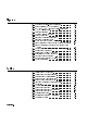
Table 1-1. Agilent 85037A Standard 1 Connector Standard Type-N (m) Option 001 Precision 7 mm Frequency Range 0.01 to 18 GHz Return Loss 0.01 to 0.04 GHz 10 dB 0.04 to 18 GHz 20 dB 2 Frequency Response 0.01 to 0.04 GHz 60.35 dB 0.04 to 18 GHz 60.18 dB Dynamic Range AC mode +20 to 055 dBm DC mode +20 to 050 dBm 3 ,5 DC Absolute Power Accuracy Power Corrected (dBm) (6dB) +20 0.25 +10 0.11 030 0.11 040 0.40 050 0.85 3 ,4 AC Dynamic Power Accuracy Default (6dB) 0.40 0.40 0.40 0.80 1.
Table 1-2. Agilent 85037B Specifications 1 Connector 3.5 mm (m) Frequency Range 0.01 to 26.5 GHz Return Loss 0.01 to 0.04 GHz 10 dB 0.04 to 18 GHz 20 dB 18 to 26.5 GHz 18 dB 2 Frequency Response 0.01 to 0.04 GHz 60.35 dB 0.04 to 18 GHz 60.18 dB 18 to 26.5 GHz 60.22 dB Dynamic Range AC mode +20 to 055 dBm DC mode +20 to 050 dBm 3,5 DC Absolute Power Accuracy Power Corrected3 (dBm) (6dB) +20 0.25 +10 0.11 030 0.11 040 0.40 050 0.85 3 ,4 AC Dynamic Power Accuracy Default (6dB) 0.40 0.40 0.40 0.80 1.
Table 1-3. Supplemental Characteristics Cable Length Weight Net Shipping 1.22m (48 in) 0.24 kg (0.5 lb) 1 kg (2.2 lb) RF Connector Mechanical Tolerances Type-N male (85037A) Recession of the male center conductor 0.207 to 0.210 in1 Precision 7 mm (85037A Option 001) Recession of the center conductor2 Collet resilience 0 to 0.003 in After you depress the collet, it must spring back out. Precision 3.5 mm (85037B) Recession of the male center conductor 0 to 0.
Table 1-4. Recommended Test Equipment Item Type-N Connector Gage Kit 7 mm Connector Gage Kit 3.
2 Installation Safety There are no hazardous voltages in this detector. Considerations Initial Inspection 1. 2. 3. 4. Check the shipping container and packaging material for damage. Check that the shipment is complete. Check connector, cable, and detector body for mechanical damage. Check the detector electrically: Either make a measurement or test to speci cations. (See Chapter 3, \Operation" or Chapter 4, \Performance Tests.
Preparation for Use Caution Electrostatic Discharge (ESD) Do not subject the detector to mechanical shock. ESD can damage the highly sensitive microcircuits in this device; charges as low as 100 V can destroy a detector. ESD damage occurs most often as you connect or disconnect a device. Use this detector at a static-safe workstation and wear a grounding strap. Never touch the input connector center contacts or the cable contact pins.
Power Requirements Cable Lead Identification Mating Connectors Caution Connecting an 85037A/B The scalar network analyzer supplies power for the detector. When you use more than one detector, use the coded cable clips (from the cable marker kit) to identify leads; place matching clips on each cable, one at each end. Table 1-3 lists connector mechanical tolerances. Microwave Connector Care (08510-90064) provides information on the proper maintenance, inspection, and gaging of connectors.
Mating a Precision 3.5 mm Connector to an SMA Connector It is possible to mate a precision 3.5 mm connector to an SMA connector, but this is not ideal because the two connectors have slightly di erent dimensions and mechanical characteristics. Mating a precision 3.5 mm connector to an SMA connector also a ects the electrical performance. (See \Electrical Performance".) Use the following procedure to safely mate 3.5 mm and SMA connectors. 1. Inspect the SMA connector. Never mate a precision 3.
Figure 2-3. SMA and 3.
: 0 C to +55 C. : Up to 95%. Protect the detector from temperature extremes, which can cause condensation. : Up to 7,620m (25,000 ft). Operating Temperature Environment Humidity Altitude Storage and Shipment Environment Store or ship the detectors in environments within the following limits: : 025 C to +75 C. : Up to 95%. Protect the detector from temperature extremes which can cause condensation. : Up to 7,620m (25,000 ft).
Returning a Detector for Service If you ship the detector to a Agilent o ce or service center ll out a blue service tag (provided at the back of this manual), and include the following information: 1. Company name and address. Do not use an address with a P.O. box number because products cannot be returned to a P.O. box. 2. A technical contact person with a complete phone number. 3. The complete model and serial number of the detector. 4. The type of service required (calibration, repair). 5.
3 Operation Operating Theory AC Detection DC Detection Cautions The 85037A/B can detect either unmodulated RF signals (DC mode) or square wave amplitude modulated RF signals (AC mode). In either detection mode, the detector provides a 27.778 kHz square wave signal to the analyzer to interpret and display. In AC detection, an RF or microwave signal is amplitude modulated with a 27.778 kHz square wave. The detector demodulates (envelope detects) and ampli es this signal to produce a 27.
Features Figure 3-1. Detector Features Connector Torque Values 3-2 Operation Tighten the 85037A type-N connector nger-tight only. Tighten the 85037A Option 001 with a torque wrench, part number 8710-1766 set at 13.8 cm-kg (12 in-lb). Tighten the 85037B with a torque wrench part number 8710-1764 set at 9.2 cm-kg (8 in-lb).
Operator's Check Operating Modes and Specifications Dynamic Accuracy Frequency Response See \Characterizing the Detector" in this chapter for a procedure that allows you to quickly check the detector. This procedure can be used as a daily check. The Agilent 85037 series precision detectors have built-in corrections for both frequency range and dynamic accuracy. These corrections are used to enhance the measurement capability of the detector. The following text explains how the corrections are made.
However, if the frequency the detector sees is di erent from what is being swept (for example, when using a mixer or multiplier), then the user must manually enter the correct detector frequencies as follows: 1. Press 4 5. 2. Select MORE . 3. Select DET FREQ . CAL NNNNNNNNNNNNNN NNNNNNNNNNNNNNNNNNNNNNNNNN 4. Select 5. Select 6. Select 7. Select Measurement System Configuration DET A,B,C or R . NNNNNNNNNNNNNNNNNNNNNNNNNNNNNNNNNNNNNNNNNNNN and use the keypad to enter a value.
DC Detection Measurements Enabling the DC Detection Mode DC detection o ers absolute power measurement capability and the ability to characterize oscillators and modulation sensitive devices. 1. On the analyzer, press 4 5. 2. Connect the detector. 3. Enable DC mode: Press 4 5 and select MODE DC . Selecting the MODE DC softkey also turns o the source square wave modulation. You must enable the DC mode to access the DC-speci c softkeys.
Note Before you zero the detector, remove all RF signals from the detector input. Even a small RF signal present during zeroing produces measurement errors. The 8757D analyzer has three types of zeroing: AUTOZRO turns o the source RF signal output and automatically zeroes the detector. REPT AZ ON/OFF automatically repeats autozero at selected intervals. MANUAL is similar to power meter zeroing.
Characterizing the Detector (Performing a Power Calibration) To obtain the best accuracy, and to meet the \corrected" dynamic accuracy speci cations, each detector must be characterized on the 8757D input on which it will be used. The characterization routine simultaneously corrects both AC and DC measurements. This routine is also useful as an operator's check to ensure the detector is operating properly. Only the 8757D with an Option 002 power calibrator have this capability.
4 Performance Tests Use the procedures in this chapter to test the detector's electrical performance to the speci cations listed in Chapter 1. None of these tests require access to the detector's interior. To completely test each detector, three tests are required: 1. return loss 2. dynamic accuracy (AC and DC uncorrected) 3. frequency response Introduction Equipment Required Note Preceding each test is an equipment table that lists which equipment you will need for that particular test.
Return Loss at a Nominal 0 10 dBm Description The return loss of the 85037 can be measured using the test system described in this procedure. The test setup is calibrated using an open/short to minimize frequency response and phasing errors. Then the detector under test (DUT) is connected to the test port of the bridge, and its return loss is measured on the 8757D. The three main sources of error in these measurements come from: 1. bridge directivity 2. source match of the bridge 3.
Table 4-1. Return Loss Equipment Table Equipment Common to all Agilent Detectors Scalar Network Analyzer 8360 Series Synthesized Sweeper Additional Equipment Required for 85037A Directional Bridge Shielded Open Short Adapter Type-N (m) to 3.5 mm (f) Additional Equipment Required for 85037A Option 001 Directional Bridge Calibrated Open/Short Adapter Type-N (m) to 3.
Connect the open to the test port of the bridge. Select STORE OPEN . Remove the open. The CRT will display: SHORT/OPEN CAL SAVED IN CH1 MEM. Press Function 4 5. Select MEAS-MEM . 4. On the 8757D: Connect the detector under test to the test port of the bridge. Press Function 4 5 4 5 4 5. Press 4 5. Use the cursor to nd the highest trace value (the worst case measurement), in each speci cation range. Write each value in the test record.
Frequency Response at a Nominal 0 10 dBm Description The frequency response of the 85037A/B detector is speci ed as the maximum peak-to-peak deviation from a constant input signal of 010 dBm, as measured over the speci ed frequency range. To simplify the measurement procedure, frequency response is measured with a nominal 010 dBm signal applied. First, the source is characterized for frequency response using a calibrated power meter/sensor combination. Second, the DUT is characterized.
Table 4-2.
Press Instrument State 4 5. Select MODE DC . 4. On the source: Press 4 5 4 5 4 5. Connect the power meter/sensor to the output of the splitter. Press 4 5 Ext Det MORE Coupling Factor 4 5 4 5. Press 4 5 40 5 4 5 and, if necessary, adjust the power level for a power meter reading within 6 0.05 dB of 010 dBm. Do not readjust the power level for the remainder of this test.
10. Connect the detector to the power splitter. On the 8757D: Press Function 4 5 to turn the cursor on. 11. On the source: Press 4 5 and enter the rst test frequency. Remember to use only the test frequencies used in steps 5 through 7. 12. Note and record on the worksheet (under the \Measured Power" column) the value indicated by the 8757D cursor display. 13. Repeat this step until all of the same frequency points have been measured. CURSOR CW Computing the Maximum Error 4-8 Performance Tests 14.
Figure 4-3. Frequency Response Graph Table 4-3. Worksheet Recommended Test Frequencies Frequency in GHz Measured Power (dBm) Source Power (dBm) Meas Power minus Source Power (dB) 0.01 0.04 0.10 2 6 10 14 16 18 20 22 24 26.
Dynamic Power Accuracy Description Procedure The dynamic power accuracy of the 85037A/B is dependent upon the raw (uncorrected) response of the detector, the correction routine of the 8757D analyzer, and the accuracy of the 8757D Option 002 calibrator. The accuracy of the calibrator is assumed to be within speci cations. This can be checked by following the performance test procedure in the 8757D manual. The correction routine is xed and cannot vary, so it is also assumed to be accurate.
13. Verify the noise oor in AC mode. Press: 4 5 AVG ON 4 5 and record the average noise oor as displayed by the cursor reading. 14. Press 4 5 4 5 MODE DC . 15. Repeat steps 6 through 12 for DC mode. The detector should be rezeroed between the 030 and 040 dBm steps. NNNNNNNNNNNNNNNNNNNN AVG CURSOR NNNNNNNNNNNNNNNNNNNNNNN PRESET SYSTEM Figure 4-4. Dynamic Power Accuracy Test Setup First Alternate Dynamic Power Accuracy Description Figure 4-5.
Second Alternate Dynamic Power Accuracy Description Figure 4-6. Second Alternate Dynamic Power Accuracy Test Setup This setup is for performing independent veri cation of dynamic accuracy in 10 dB increments up to +20 dBm in DC mode. Table 4-4. Additional Equipment Function Generator 50 MHz Bandpass Filter Procedure 4-12 Performance Tests Agilent 8116A 08757-80027 1. Set the 8757D for CW, DC mode, cursor on. 2. Set the step attenuator to 20 dB. 3.
Table 4-5.
Table 4-5. Test Record for 85037A (2 of 3) Model Test Equipment Used 1. 2. 3. 4. 5. 6. 7. 8.
Table 4-5. Test Record for 85037A (3 of 3) Serial Number: Report Number: Test Description Speci cation Return Loss at a Nominal 010 dBm Date: Measured Results Measurement Uncertainty1 0.01 to 0.04 GHz 10 dB 0.04 to 18 GHz 20 dB 61.0 dB 62.4 dB 60.35 dB 60.18 dB 60.18 dB 60.25 dB 60.4 dB 60.4 dB 60.4 dB 60.8 dB 61.3 dB 055 dBm 60.2 dB 60.13 dB 60.22 dB 60.30 dB 60.36 dB 60.4 dB 60.4 dB 60.4 dB 60.8 dB 61.3 dB 60.2 dB 60.13 dB 60.22 dB 60.3 dB 60.
4-16 Performance Tests
Table 4-6.
Table 4-6. Test Record for 85037A Option 001 (2 of 3) Model Test Equipment Used 1. 2. 3. 4. 5. 6. 7. 8.
Table 4-6. Test Record for 85037A Option 001 (3 of 3) Serial Number: Report Number: Test Description Speci cation Return Loss at a Nominal 010 dBm Date: Measured Results Measurement Uncertainty1 0.01 to 0.04 GHz 10 dB 0.04 to 18 GHz 20 dB 6.7 dB 61.4 dB 60.35 dB 60.18 dB 60.18 dB 60.25 dB 60.4 dB 60.4 dB 60.4 dB 60.8 dB 61.3 dB 055 dBm 60.2 dB 60.13 dB 60.22 dB 60.3 dB 60.36 dB 60.4 dB 60.4 dB 60.4 dB 60.8 dB 61.3 dB 60.2 dB 60.13 dB 60.22 dB 60.3 dB 60.
4-20 Performance Tests
Table 4-7.
Table 4-7. Test Record for 85037B (2 of 3) Model Test Equipment Used 1. 2. 3. 4. 5. 6. 7. 8.
Table 4-7. Test Record for 85037B (3 of 3) Serial Number: Report Number: Test Description Speci cation Return Loss at a Nominal 010 dBm Date: Measured Results Measurement Uncertainty1 0.01 to 0.04 GHz 10 dB 0.04 to 18 GHz 20 dB 18 GHz to 26.5 GHz 18 dB 60.7 dB 61.4 dB 62.0 dB 60.35 dB 60.18 dB 60.22 dB 60.18 dB 60.25 dB 60.3 dB 6 0.4 dB 6 0.4 dB 6 0.4 dB 6 0.8 dB 6 1.3 dB 055 dBm 60.2 dB 60.13 dB 60.22 dB 60.3 dB 60.36 dB +10 dBm 6 0.4 dB 6 0.4 dB 0 dBm + 0.
5 Adjustments Introduction Two adjustments can be performed on the 85037A/B. 1. coarse zero adjustment 2. feedthrough nulling adjustment Normally these two adjustments do not need to be performed. They should only be performed if the zeroing routine fails. Before attempting any adjustments: Turn on all equipment and allow a minimum of 30 minutes warmup time. Note that the adjustments are interactive and must be performed in the order given.
Coarse Zero Adjustment Description The coarse zero adjustment centers the detector's DC preamp input o set voltage within the built-in automatic zero routine's range. This is accomplished by adjusting for the lowest overall indication of noise on the 8757D. When the level is minimized, it indicates that the range has been properly centered. Remove the detector's outer covers and metal housing to allow access for making the adjustments.
Figure 5-2. Coarse Zero Adjustment Feedthrough Nulling Adjustment Description Procedure The feedthrough nulling is adjusted for best DC accuracy below 045 dBm. This is accomplished by adjusting for the highest overall indication of noise on the 8757D. When the level of noise is maximized, it indicates that the feedthrough is nulled. Equipment: 8757D scalar network analyzer Perform the following steps in order. Connect the equipment as shown in Figure 5-1. On the 8757D: 1. Press 4 5. 2.
10. Press 4 5 DC DET ZERO MANUAL . The display indicates:REMOVE RF FROM DC DETECTORS. If you have connected the detector to an RF output, disconnect it. 11. Press CONT . When the routine is complete the display indicates: MANUAL ZERO COMPLETED. 12. Locate the Feedthrough Null multi-turn potentiometer which is on the top side of the PC board, (the same side as the cable wires). Adjust it one half turn (either direction). See Figure 5-3. 13.
6 Replaceable Parts Introduction Ordering Parts This section provides replaceable parts and ordering information. To order a part listed in the replaceable parts Table 6-2, quote the Agilent part number, indicate the quantity required and address the order to your nearest Agilent o ce.
To request information on a part that is not listed in the replaceable parts table, include the instrument model number and a description of the part and its function. Address the inquiry to the nearest Agilent o ce. Figure 6-1. Detectors and Cable Marker Kit Table 6-1.
Table 6-2. Replaceable Parts and Accessories Part Description Agilent Model or Part Number Rebuilt/Exchange Assemblies 85037A Type-N 85037A Option 001 7 mm 85037B 3.5 mm Accessories Connector Gage Kits Type-N 7 mm 3.5 mm 85037-69006 85037-69007 85037-69008 85054-80011 85050-80012 11752-60106 Collet Extractor Tool For 85037A Option 001 5060-0370 Adapters Type-N (f) to BNC (m) Type-N (m) to Type-N (m) 3.5 mm (f) to 3.5 mm (f) Type-N (m) to APC-7 (Option 001 only) APC-3.
Figure 6-2.
By internet, phone, or fax, get assistance with all your test & measurement needs. Table 6-3. Contacting Agilent Online Assistance: www.agilent.
7 Service Caution Error Messages This product is susceptible to damage from electrostatic discharge (ESD). When you perform any of the following procedures, wear a grounded static-strap and work at a static-safe workstation. The message EEPROM read failed -- A (B,C or R) Indicates that the EEPROM calibration constants are either corrupted or unable to be read from the detector. The problem could be in either the detector or the 8757D. Try another detector to isolate the cause.
Repair Replacing the Detector Removing the Covers 1. Remove the plastic covers from the existing detector. (See \Removing the Covers.") 2. Install the covers on the replacement detector. 3. Perform an operator's check. (See \Operator's Check" in Chapter 3.) 4. If the replacement is a restored exchange detector, return the defective detector using the packing material supplied. 1. Place the detector with its narrow side on a at surface, with the RF connector facing away from you. (See Figure 7-1.) 2.
Repair Replacing the Cable Assembly (W1) Caution 1. Remove the plastic covers from the detector. (See \Removing the Covers.") 2. Remove the two screws at the cable end of the metal housing. 3. Slide the metal housing away from the RF connector, completely exposing the printed circuit (PC) assembly. 4. Unsolder all cable wires from the PC assembly. 5. With the PC assembly facing up, carefully secure the detector frame in a vice. Do not grip the PC assembly.
Repair Figure 7-2.
A Caring for Connectors This appendix provides a brief introduction to the fundamentals of proper connector care, as important to good measurements as proper instrument calibration and adjustment. This appendix is intended to provide basic information and tell you where to nd more: Agilent's Microwave Connector Care . (See Table 6-2 for ordering information.) Remember A damaged connector can destroy any connector attached to it. Basic connector care comprises three parts: 1. visual inspection 2.
Mechanical Inspection A-2 Caring for Connectors Because coaxial connector mechanical tolerances can be very precise (on the order of a few hundredths of microinches), even a perfectly clean, unused connector can cause trouble if it is mechanically out of speci cation. Use a connector gage to mechanically inspect coaxial connectors. Gage a connector at the following times: Before you use it for the rst time.
Index A B C D AC detection, 1-2, 3-1 adjustments, 5-1 coarse zero adjustment, 5-1{2 feedthrough nulling adjustment, 5-1{2 autozero, 4-7 bridge directivity, 4-2 source match, 4-2 cable lead identi cation, 2-3 replacing, 7-3 cable assembly, 7-3 characterizing the detector, 3-7 characterizing the source, 4-7 cleaning connectors, A-1 coarse zero adjustment, 5-1 computing the maximum error, 4-8 worksheet, 4-9 connector care, A-1 cleaning, A-1 mating, 2-3 mating a 3.
E F feedthrough nulling adjustment, 5-1 oor mat use, 2-2 frequency response, 4-5 correction constants, 3-3 correction factors, 3-3 G gaging, 2-4 H heel strap use, 2-2 I M O P Index-2 electrical performance, 4-1 electrostatic discharge (ESD), 2-2 cautions, 3-1 equipment, 4-6 exchange credit, 7-1 initial inspection, 2-1 installation, 2-1 mat use, 2-2 measurement errors sources, 4-2 measurements AC detection, 3-6 DC detection, 3-5 measurement system con guration, 3-4 measuring the detector, 4-7 m
R S T W Z re ection measurements, 1-2 removing covers, 7-2 repairable parts, 7-1 replaceable parts, 6-1 replacing cable, 7-3 detector, 7-2 return loss, 4-3 test description, 4-2 safety considerations, 2-1 service, 7-1 returning detector for service, 2-7 setup AC detection mode, 3-4{6 DC detection mode, 3-4{5 static-safe practices, 2-2 workstation, 2-2 storage and shipment, 2-6 environment, 2-6 table mat use, 2-2 test records, 4-13 transmission measurements, 1-2 W1 cable replacement, 7-3 wrist strap use