Supplemental Operator’s Guide for the Agilent 35670A Dynamic Signal Analyzer By: David Forrest Seattle Sound and Vibration, inc. Print Date: December, 2000 ãSeattle Sound and Vibration, inc. 1996, 2000. All rights reserved. Agilent Part number 35670-90059 Special Permission Amoco Corporation and Agilent Technologies, Inc are granted full editing, duplication and distribution privileges.
AGILENT 35670A Supplemental Operator’s Guide SECTION 1 : TURNING ON THE AGILENT 35670A .......................................................................................... 1 SECTION 2 : MEASUREMENT STATE AFTER TURN-ON............................................................................... 2 SECTION 3 : MEASURING WITH TRANSDUCERS........................................................................................... 3 USING ICP-TYPE TRANSDUCERS WITH THE AGILENT 35670A .......................
AGILENT 35670A Supplemental Operator’s Guide SECTION 11 : MODAL TESTING USING A HAMMER AND ACCELEROMETER ................................. 25 SETTING UP THE TRANSDUCER PARAMETERS ......................................................................................................... 25 SETTING UP INPUT RANGE ...................................................................................................................................... 26 CHOOSING A PRELIMINARY FREQUENCY SPAN ........................
AGILENT 35670A Supplemental Operator’s Guide SECTION 21 : USING AN EXTERNAL TRIGGER FOR TIME AVERAGING ........................................... 60 SPECIFY USER LEVELS FOR TRIGGERING ................................................................................................................ 60 CHARACTERIZING THE EXTERNAL TRIGGER ........................................................................................................... 60 SETTING UP EXTERNAL TRIGGER ...................................
AGILENT 35670A Supplemental Operator’s Guide Section 1 : Turning On the AGILENT 35670A The entire turn-on procedure for the AGILENT 35670A takes 40 seconds. In that time the analyzer completes a hardware self-test, boots its operating system, completes a front end self-calibration and autoranges all input channels. The default measurement state of the analyzer is a two-channel FFT measurement with a span of 51.
AGILENT 35670A Supplemental Operator’s Guide Section 2 : Measurement State After Turn-on Inst Mode FFT Measurement Source Channels 2 INPUT Meas Data Data A Data C PWR SPEC1 TIME1 Data B Data D PWR SPEC2 TIME2 MAG-LOG REAL Coord B Coord D MAG-LOG REAL Trac Coord Coord A Coord C Freq Start Center Rec Len 0 Hz 25.6 kHz 7.8125 ms Stop Span Resoltn 51.2 kHz 51.2 kHz 400 Window CH1 CH2 CH3 CH4 FLATTOP FLATTOP FLATTOP FLATTOP BW BW BW BW 488.88 488.88 488.88 488.
AGILENT 35670A Supplemental Operator’s Guide Section 3 : Measuring with Transducers The AGILENT 35670A can be used with a broad range of transducers. Transducers can use an external preamplifier to convert the raw signal into a voltage that is compatible with the AGILENT 35670A. Some transducers have internal circuitry which provides preamplification, however these internal circuits must be powered externally.
AGILENT 35670A Supplemental Operator’s Guide For example, if an accelerometer has am internal sensitivity of 25 pC/g, and a charge amplifier has a gain setting of 10 mV/pC, then the resulting transducer sensitivity is 250 mV/g. However is the gain setting on the charge amplifier is changed to 1 mV/pC, then the resulting sensitivity would then be 25 mV/g. Specifying Transducer Sensitivity and Units The AGILENT 35670A provides the ability to convert electrical signals into Engineering Units.
AGILENT 35670A Supplemental Operator’s Guide Section 4 : Measuring a Single Channel Power Spectrum - Displacement This section contains procedures for setting up and measuring a single channel power spectrum of displacement using an AGILENT 35670A Dynamic Signal Analyzer. Included are steps to select single channel operation, set up transducer parameters, frequency span, choose input range, select windowing, and turn on averaging in order to improve measurement accuracy.
AGILENT 35670A Supplemental Operator’s Guide Any frequency below 51.2 kHz may of course be entered, however the analyzer will select the lowest span that contains the desired frequency. For example, if 1200 Hz is entered, the analyzer is switched to a span of 1600 Hz. Frequency Spans Available for the AGILENT 35670A 102.4 kHz * 100 Hz 51.2 kHz 50 Hz 25.6 kHz 25 Hz 12.8 kHz 12.5 Hz 6.4 kHz 6.25 Hz 3.2 kHz 3.125 Hz 1.6 kHz 1.5625 Hz 800 Hz 0.78125 Hz 400 Hz 0.390625 200 Hz 0.
AGILENT 35670A Supplemental Operator’s Guide Input CH1 Rng: 501.7819 mVpk CH3 Rng: 2.5149 Vpk Date: 10-02-96 Time: 08:42:00 PM A: CH1 Pwr Spec 1 Vrms LogMag decades X:160 Hz CH2 Rng: 631.706 mVpk CH4 Rng: 2.5149 Vpk Y:169.558 mVrms 6 1 uVrms 0Hz 800Hz Quantifying Power Spectrum Results Use the marker knob to read the amplitude at any measured frequency.
AGILENT 35670A Supplemental Operator’s Guide Section 5 : Improving Measurement Results Frequency Zooming to Increase Resolution The AGILENT 35670A has the ability to zoom in on a signal to show detail with very fine resolution. After choosing a center frequency, it is possible to decrease the span and therefore increase the resolution all the way down to 61 µHz. To zoom in on a signal, move the marker to the desired center frequency, then: • • • Press the [Freq] hardkey. Press the [CENTER] softkey (F2).
AGILENT 35670A Supplemental Operator’s Guide If continuous real-time measurements over a long duration are required, and absolutely no overload conditions are desired, then a fixed input range can be set that is greater than any signal expected. During periods of low signal level, dynamic range will not be optimal, however the entire measurement can be completed without overloads. To set up a fixed range of 1 volt: • • Press the [Input] hardkey.
AGILENT 35670A Supplemental Operator’s Guide Systm Util Date: 10-02-96 Time: 08:40 PM Date: 01-02-04 Time: 12:44:00 PM A: CH1 Pwr Spec 1 Vrms LogMag decades 10 Hz Y:174.
AGILENT 35670A Supplemental Operator’s Guide Section 6 : Measuring a Single Channel Time Waveform This section contains procedures for setting up and measuring a single channel time waveform using an AGILENT 35670A Dynamic Signal Analyzer. Included are steps to select single channel operation, set up the trace time length, and set up triggering to capture a transient event. Instructions will also be presented to scale the time trace.
AGILENT 35670A Supplemental Operator’s Guide Selecting Time Record Length The default time record length at a frequency span of 51.2 kHz is only 7.8 ms, which is usually not enough time to capture a mechanical event or observe a transducer’s time domain signal. To increase the time record length to 0.25 s, perform the following steps: • • • Press the [Freq] hardkey Press the [RECORD LENGTH] softkey (F8) Enter 0.25 and then press the [S] softkey (F1) The analyzer selects a new frequency span of 1.
AGILENT 35670A Supplemental Operator’s Guide • Press the [ARM] softkey (F9) again. Event Triggering The AGILENT 35670A has the ability to trigger the acquisition of a time waveform based on the slope and level of the measured signal. To set up triggering properly, the polarity of the measured pulse must be known in advance: will the event start with a negative slope or positive slope? Will the event be mostly positive or mostly negative? Use trial measurements to determine polarity if unknown.
AGILENT 35670A Supplemental Operator’s Guide Input CH1 Rng: 1.0012 Vpk CH3 Rng: 2.5149 Vpk Date: 10-02-96 Time: 08:47:00 PM A: CH1 Time 2.5 V Real X:38.0859 ms CH2 Rng: 631.706 mVpk CH4 Rng: 2.5149 Vpk Y:1.06837 V 500 mV /div -2.5 V -9.7656ms 489.7461ms Quantifying Time Trace Results Use the marker knob to read the amplitude at any time during the trace.
AGILENT 35670A Supplemental Operator’s Guide Section 7 : Measuring Dual Channel Spectra This section contains procedures for setting up and measuring a dual channel spectrum using an AGILENT 35670A Dynamic Signal Analyzer. Procedures are similar to those in the section “Measuring Single Channel Spectrum,” however display setup and results are different and will be described here.
AGILENT 35670A Supplemental Operator’s Guide • • • • Press the [Meas Data] hardkey. Press the [CHANNEL 1 2 3 4] softkey (F1) until 2 is highlighted. Press the [Scale] hardkey. Toggle the [AUTOSCALE ON OFF] softkey (F1) until ON is highlighted. Note: many of these keystrokes are not necessary if performed in the given order because the analyzer defaults to many of these settings. To acquire dual channel spectra, • Press the yellow [Start] hardkey.
AGILENT 35670A Supplemental Operator’s Guide Use the marker knob to read the amplitude at any measured frequency for Channel 1 in Trace A. To set up the marker for Channel 2 in Trace B, • • • • Press the [Active Trace] hardkey. Press the [B] softkey (F2). Press the [Marker] hardkey. Toggle the [MARKER ON OFF] softkey (F1) until ON is highlighted. • • Press the [Active Trace] hardkey. Press the [A] softkey (F1). The marker knob is now active for Trace B, which is Channel 2.
AGILENT 35670A Supplemental Operator’s Guide Section 8 : Improving Dual Channel Measurement Results Maximizing Dynamic Range Autoranging to maximize the dynamic range of measurements in the AGILENT 35670A can function on all channels simultaneously. Therefore all capability previously mentioned for single-channel front-end ranging is available for dualchannel operation. To set up autorange on all channels, follow these steps: • • • Press the [Input] hardkey. Press [ALL CHANNELS] softkey (F2).
AGILENT 35670A Supplemental Operator’s Guide Avg Type: RMS [FFT] Update Rt: 5 Date: 10-02-96 Time: 08:51:00 PM A: CH1 Pwr Spec 1 Vrms LogMag decades X:60 Hz X:60 Hz 0Hz B: CH2 Pwr Spec 100 mVrms decades Y:112.185 mVrms 5 10 uVrms LogMag Number: 10 Overlap: 0 % AVG: 10 Y:95.
AGILENT 35670A Supplemental Operator’s Guide Section 9 : Measuring Dual Channel Time Waveforms This section contains procedures for setting up and measuring a single channel time waveform using an AGILENT 35670A Dynamic Signal Analyzer. Included are steps to select single channel operation, set up the trace time length, and set up triggering to capture a transient event. Instructions will also be presented to scale the time trace.
AGILENT 35670A Supplemental Operator’s Guide • • • • • • • • • • • Press the [CHANNEL 1 2 3 4] softkey (F1) until 1 is highlighted. Press the [TIME CHANNEL 1] softkey (F5) Press the [Scale] hardkey. Toggle the [AUTOSCALE ON OFF] softkey (F1) until ON is highlighted.. Press the [Active Trace] hardkey. Press the [B] softkey (F1) Press the [Meas Data] hardkey. Press the [CHANNEL 1 2 3 4] softkey (F1) until 2 is highlighted. Press the [TIME CHANNEL 2] softkey (F5) Press the [Scale] hardkey.
AGILENT 35670A Supplemental Operator’s Guide Then set up trigger parameters (for a positive event, positive slope) as follows: • • • • Press the [TRIGGER SETUP] softkey (F6) Press the [CHANNEL LEVEL] softkey (F1) Enter 5 then press the [PERCENT (%)] softkey (F4) Press the [SLOPE POS NEG] softkey (F5) until POS is highlighted. Trigger Delay Both channels should acquire data using the same pre-trigger delay. To set up a 0.
AGILENT 35670A Supplemental Operator’s Guide Using Markers with Dual Channel Time Measurements Compare the time trace of Channel 1 with Channel 2 using two techniques: peak tracking and coupled markers. With peak tracking active on both channels, it is possible to measure an event with two channels and easily compare peak amplitudes. Set set up peak tracking for both channels, do the following: • • • • • • • • Press the [Active Trace] hardkey. Press the [A] softkey (F1). Press the [Marker] hardkey.
AGILENT 35670A Supplemental Operator’s Guide • • • • • • Press the [Active Trace] hardkey. Press the [A B C D] softkey (F7). Press the [Scale] hardkey. Toggle the [AUTOSCALE ON OFF] softkey (F1) until ON is highlighted.. Press the [Active Trace] hardkey. Press the [A] softkey (F1). The default QUAD display shows Channel 1 power spectrum in Trace A, Channel 2 power spectrum in Trace B, Channel 1 time in Trace C, and Channel 2 time in Trace D.
AGILENT 35670A Supplemental Operator’s Guide Section 11 : Modal Testing Using a Hammer and Accelerometer Hammer testing is often the easiest and quickest technique for measuring frequency response functions used in modal analysis. Instructions for using a hammer with a force transducer and an accelerometer to measure frequency response functions are presented. Setting Up the Transducer Parameters Connect the force transducer on the hammer to Channel 1.
AGILENT 35670A Supplemental Operator’s Guide • • • Toggle the [XDCR UNIT ON OFF] softkey (F4) until ON is highlighted. Press the [XDCR UNIT LABEL] softkey (F7). Select the [g] softkey (F2). Setting Up Input Range Use CH* AUTO UP ONLY as the autorange routine as follows: • • • Press the [Input] hardkey. Press [ALL CHANNELS] softkey (F2). Select the [CH* AUTO UP ONLY] softkey (F5). Then tap the structure with the hammer once.
AGILENT 35670A Supplemental Operator’s Guide • • • • Press the [TRIGGER SETUP] softkey (F6) Press the [ALL CHANNELS] softkey (F8) Press the [CHANNEL * DELAY] softkey (F9) Enter -.01 then press the [S] softkey (F1) • Press the yellow [Start] hardkey. Now to check that the trigger parameters are correct, The analyzer should show in highlighted text above the trace: WAITING FOR CH 1 TRIGGER Tap the hammer on the test structure to see if the measurement will trigger.
AGILENT 35670A Supplemental Operator’s Guide Window Type: Force/Expo [FFT] Date: 10-02-96 Time: 09:02:00 PM A: CH1 Time 80 mV Real -20 mV -9.766ms B: CH2 Time 300 mV Real -200 mV -9.766ms C: CH1 Win Time 70 mV Real -30 mV -9.766ms D: CH2 Win Time 250 mV Real -250 mV -9.766ms Width: 15 ms Decay: 30 ms X:488.281 us Y:67.1154 mV X:488.281 us Y:-74.925 mV X:488.281 us Y:48.1237 mV X:488.281 us Y:-53.234 mV 115.112ms 115.112ms 115.112ms 115.
AGILENT 35670A Supplemental Operator’s Guide window time constant of 62.5 ms. To set up these Force/Response windows, follow these steps: • • • • • • • Press the [Window] hardkey. Press the [FORCE EXPO] softkey (F4). Press the [FORCE EXPO SETUP] softkey (F6). Press the [FORCE WIDTH] softkey (F6). Enter 36 and then press the [mS] softkey (F2). Press the [EXPO DECAY] softkey (F7). Enter 62.5 and then press the [mS] softkey (F2).
AGILENT 35670A Supplemental Operator’s Guide significantly. Ten averages may take longer, but may be necessary when testing difficult, non-linear structures. To set up five averages, follow these steps: • • • • Press the [Avg] hardkey. Toggle the [AVERAGE ON OFF] softkey (F1) until ON is highlighted. Press the [NUMBER AVERAGES] softkey (F2). Enter 5 and press the [ENTER] softkey (F1). • • Press the [Avg] hardkey. Toggle the [OVLD REJ ON OFF] softkey (F1) until ON is highlighted.
AGILENT 35670A Supplemental Operator’s Guide Changing Frequency Span Changing frequency span or resolution affects three important parameters in hammer testing which must be changed to correspond to the new time record length: Trigger Delay, Force Window Width, and Response Window Decay Time. The following relationship between the parameters can be used as a guideline: T = N (1024 . F) Where T is the time record length in seconds, N is the resolution in lines, and F is the frequency span in Hz.
AGILENT 35670A Supplemental Operator’s Guide Section 12 : Hammer Test Setup Without a Force Transducer Hammer testing for modal analysis without a force transducer can yield usable results if an accelerometer is placed on the hammer and used to trigger the measurement.
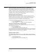
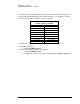
AGILENT 35670A Supplemental Operator’s Guide Section 13 : Order Domain Results in List Mode Machinery run-ups and run-downs can be analyzed with order analysis, which is spectral analysis normalized to RPM. Results can be simplified by examining only a list of amplitude versus order, so that only desired results are examined. To set up and measure a list of 10 orders for a machinery run-up, follow these steps: • • • • • • • Press the green [Preset] hardkey Press [DO PRESET] softkey (F1).
AGILENT 35670A Supplemental Operator’s Guide • • • • • • • Enter 4 and press the [ORDERS] softkey (F1). Enter 5 and press the [ORDERS] softkey (F1). Enter 6 and press the [ORDERS] softkey (F1). Enter 7 and press the [ORDERS] softkey (F1). Enter 8 and press the [ORDERS] softkey (F1). Enter 9 and press the [ORDERS] softkey (F1). Enter 10 and press the [ORDERS] softkey (F1). • • • • • Insert a 3.5” diskette into the AGILENT 35670A Press the [Save/Recall] hardkey. Press the [SAVE MORE] softkey (F3).
AGILENT 35670A Supplemental Operator’s Guide Section 14 : Comparing Two-Channel Real-Time Spectra with Recalled Data Compare two channels of real-time data with spectra stored in registers using the UPPR/LOWR FRNT/BACK display format of the AGILENT 35670A. Note that the real-time data should be measured with the same frequency and resolution as the stored data if valid, direct comparisons are desired. Preset the analyzer as follows: • • • Press the green [Preset] hardkey Press [DO PRESET] softkey (F1).
AGILENT 35670A Supplemental Operator’s Guide • • • Press the [MORE CHOICES] softkey (F9). Press the [DATA REGISTER] softkey (F8). Press the [D2] softkey (F2). Recalling the Spectra from Disk Use data registers D1 and D2 to contain the spectra used for comparison. D1 is compared to Channel 1 real-time data, and D2 is compared to Channel 2 real-time data. Comparison data must either be measured, then stored into data registers D1 and D2, or recalled into registers D1 and D2 from disk or non-volatile RAM.
AGILENT 35670A Supplemental Operator’s Guide • • • • • • Press the [Save/Recall] hardkey. Press the [RECALL DATA] softkey (F4). Press the [RCL TRACE AND SCALE] softkey (F1). Press the [FROM FILE INTO D1] softkey (F1). Press the [CLEAR ENTRY] softkey (F9). Enter COMPARE1.DAT and press the [ENTER] softkey (F1). Data from the file “COMPARE1.DAT” now appears in data register D1. Next, recall “COMPARE2.DAT” into dataregister D2 as follows: • • • • • • Press the [Save/Recall] hardkey.
AGILENT 35670A Supplemental Operator’s Guide Scaling for traces A and B are now identical. To accomplish the same trace scaling for C and D, follow these steps: • • • • • • Press the [Active Trace] hardkey. Press the [C D] softkey (F1). Press the [Scale] hardkey. Toggle the [AUTOSCALE ON OFF] softkey (F1) until ON is highlighted. Press the [Y PER DIV (DECADES)] softkey (F6). Enter 2 and press the [ENTER] softkey (F1).
AGILENT 35670A Supplemental Operator’s Guide Section 15 : Waterfall Spectra at Time Intervals Waterfalls on the AGILENT 35670A can be used to examine and compare spectra at fixed intervals of time. This is especially useful when measuring non-stationary signals from machinery, such as during run-ups and run-downs. To see a waterfall display of the vibration signature, follow these steps: Preset the analyzer as follows: • • • Press the green [Preset] hardkey Press [DO PRESET] softkey (F1).
AGILENT 35670A Supplemental Operator’s Guide • • • Press the [Disp Format] hardkey. Press the [WATERFALL SETUP] softkey (F8). Toggle the [WATERFALL ON OFF] softkey (F1) until ON is highlighted. The default number of waterfall steps is 15, which means only 15 spectra are kept in memory and as new data is taken, the oldest spectra is discarded.
AGILENT 35670A Supplemental Operator’s Guide This makes the waterfall trace active. • • Press the [Marker Fctn] hardkey. Press the [WATERFALL MARKERS] softkey (F5). • Press the [SAVE AND DISP DATA] softkey (F5). The SLICE SELECT softkey will be active. Use the marker knob to move the cursor to the frequency of interest. This one keystroke saves the selected slice into data register D2 and changes the Meas Data of Trace A to display data register D2.
AGILENT 35670A Supplemental Operator’s Guide Section 16 : Waterfall Spectra at RPM Intervals Spectra can be acquired at fixed RPM intervals with RPM STEP ARM. This feature allows spectra to be taken at uniform RPM intervals even during erratic run-ups. Setting Up the Tachometer Connect the tachometer signal to the TACH BNC connector on the back of the AGILENT 35670A.
AGILENT 35670A Supplemental Operator’s Guide • Press 50 then the [RPM] softkey (F1). • • • • • • Press the [Active Trace] hardkey. Select the [B] softkey (F2). Press the [Disp Format] hardkey. Select the [WATERFALL SETUP] softkey (F8). Select the [WATERFALL STEPS] softkey (F8). Enter 15 and then press the [ENTER] softkey (F1).
AGILENT 35670A Supplemental Operator’s Guide Marker Fcn Trace: B [Watrfall] Base Supr: 0 % Date: 07-24-96 Time: 11:31:00 PM Save Reg: D2 Height: 57 % A: D2 Pwr Spec 1 Vrms LogMag 4 decades 100 u 0Hz B: CH1 Pwr Spec 1 Vrms Slice:122 Hz Trace:4.311 kRPM 800Hz LogMag 100 uVrms 4.883 kRPM 3.
AGILENT 35670A Supplemental Operator’s Guide Section 17 : Two-Channel Absolute and Differential Amplitude Measurement Measuring the relative motion between points on a machine can provide information regarding clearances and forces. These measurements may also demonstrate a susceptibility of a machine to a particular mode of vibration. Absolute motion can be measured as a power spectrum, with units of peak-to-peak displacement in mils.
AGILENT 35670A Supplemental Operator’s Guide • • • • • • • • Toggle the [AUTOSCALE ON OFF] softkey (F1) until ON is highlighted.. Press the [Active Trace] hardkey. Press the [B] softkey (F1) Press the [Meas Data] hardkey. Press the [CHANNEL 1 2 3 4] softkey (F1) until 2 is highlighted. Press the [TIME CHANNEL 2] softkey (F5) Press the [Scale] hardkey. Toggle the [AUTOSCALE ON OFF] softkey (F1) until ON is highlighted.
AGILENT 35670A Supplemental Operator’s Guide • • difference in motion between Channel 1 and Channel 2 in mils peak-topeak phase angle between the two channels. Set up the AGILENT 35670A • • • • • • • • Press the green [Preset] hardkey Press [DO PRESET] softkey (F1). Press the [Pause/Cont] hardkey if desired. Press the [Freq] hardkey Enter 800 and then press the [Hz] softkey (F2). Press the [Input] hardkey. Press the [ALL CHANNELS] softkey (F2). Select the [CH* AUTO UP ONLY] softkey (F5).
AGILENT 35670A Supplemental Operator’s Guide • • • Toggle the [CHANNEL 1 2 3 4] softkey (F1) until 2 is highlighted. Press the [LIN SPEC CHANNEL 2] softkey (F3). Press the [ENTER] softkey (F7). Set up display • • Press the [Disp Format] hardkey. Press the [QUAD] softkey (F6). • • • • • • • • • Press the [Active Trace] hardkey. Press the [A] softkey (F1). Press the [Meas Data] hardkey. Press the [CHANNEL 1 2 3 4] softkey (F1) until 1 is highlighted.
AGILENT 35670A Supplemental Operator’s Guide • • • • Press the [Active Trace] hardkey again. Press the [D] softkey (F2). Press the [Trace Coord] hardkey. Press the [PHASE] softkey (F4). Start measurement • Press the yellow [Start] hardkey. The AGILENT 35670A will now measure motion of Channel 1 and 2 and show the results in Traces A and B. The difference in motion between Channel 1 and Channel 2 is shown in Trace C. The phase angle between channels is shown in Trace D.
AGILENT 35670A Supplemental Operator’s Guide Section 18 : Measuring Frequency Response with the AGILENT 35670A Frequency response functions characterize the behavior of systems to external stimuli. For mechanical systems, the stimulus can be a transient force such as an impact from a hammer, or a broadband stimulus, such as random excitation from an electrodynamic shaker. The response is usually motion of the system, measured with and accelerometer, velocity transducer, or displacement probe.
AGILENT 35670A Supplemental Operator’s Guide • • • Attach one end of stinger to shaker and one end to force transducer Connect amplifier output to shaker Connect amplifier input to AGILENT 35670A source • • Connect force transducer to Channel 1 Connect accelerometer to Channel 2 • • • Turn on the AGILENT 35670A, or Press the green [Preset] hardkey Press the yellow [Pause/Cont] hardkey if desired.
AGILENT 35670A Supplemental Operator’s Guide Choose measurement parameters • • • • • • • Press the [Freq] hardkey Enter 800 and then press the [Hz] softkey (F2) Press the [Avg] hardkey. Press the [NUMBER AVERAGES] softkey (F2), enter 4, then press the [ENTER] softkey (F1). Turn on averaging by pressing the [AVERAGE ON OFF] softkey (F1) until ON is highlighted. Press the [Window] hardkey Press the [UNIFORM] softkey (F3). Set up display parameters • • • • • • • • • • • • Press the [Disp Format] hardkey.
AGILENT 35670A Supplemental Operator’s Guide • Turn up the level control on the shaker amplifier until the excitation is noticeable, but does not buzz or rattle. If buzzing or rattling is heard, then either the level is too high or the structure is loose and must be quieted. Press the [MORE CHOICES] softkey (F9) Press the [BURST RANDOM] softkey (F2) • • Set up the trigger • • Press the [Trigger] hardkey. Press the [SOURCE TRIGGER] softkey (F4).
AGILENT 35670A Supplemental Operator’s Guide • • • • • • • Press the [Disp Format] hardkey. Press the [SINGLE] softkey (F1) Press the [Active Trace] hardkey. Press the [ A ] softkey (F1). Press the [Trace Coord] hardkey. Press the [MORE CHOICES] softkey (F6). Press the [NYQUIST DIAGRAM] softkey (F4). Trac Coord A: Nyquist [FFT] C: Real Date: 10-02-96 Time: 09:49:00 PM A: Freq Resp2/1 200 e-3 Imag Nyquist R:-117.6 e-3 B: Phase D: Real I:-101.3 e-3 +j X:262 Hz 50 e-3 -1 /div -300 e-3 +1 -366.
AGILENT 35670A Supplemental Operator’s Guide • • • • • • • • • Toggle the [AUTOSCALE ON OFF] softkey (F1) until ON is highlighted. Press the [Active Trace] hardkey. Press the [ A ] softkey (F2). Press the [Trace Coord] hardkey. Press the [MORE CHOICES] softkey (F6). Press the [REAL PART] softkey (F2). Press the [Active Trace] hardkey. Press the [ B ] softkey (F2). Press the [IMAGINARY PART] softkey (F3).
AGILENT 35670A Supplemental Operator’s Guide Section 19 : Two Spectral Traces Showing Mils and Ips while EU is G Measure an accelerometer signal and display velocity and displacement spectra with the UPPER/LOWER display format in the AGILENT 35670A as follows: Preset the AGILENT 35670A • • • • Turn on the AGILENT 35670A, or Press the green [Preset] hardkey Press the yellow [Pause/Cont] hardkey if desired. Press [CHANNELS 1 2 4 ] softkey (F7) until 1 is highlighted.
AGILENT 35670A Supplemental Operator’s Guide • • • • • • • Press the [Trace Coord] hardkey. Press the [Y UNITS] softkey (F8) Toggle the [AMPLITUDE PK PP RMS] softkey (F4) until PK is highlighted. Press the [XDCR UNIT CONVERT] softkey (F4) Press the [inch/s (VEL)] softkey (F6) Press the [Scale] hardkey. Toggle the [AUTOSCALE ON OFF] softkey (F1) until ON is highlighted.
AGILENT 35670A Supplemental Operator’s Guide Section 20 : Peak Hold During a Machine Run-up and Coast-Down Peak amplitudes experienced during run-ups and coast-downs can be measured directly with the AGILENT 35670A using peak hold. Although the resulting spectra will indicate the maximum amplitude measured in each frequency bin during the course of the run-up and run-down, it is not possible to determine from this information whether the peak was due to the fundamental frequency or a harmonic.
AGILENT 35670A Supplemental Operator’s Guide • • • • • Press the [Active Trace] hardkey. Press the [ A ] softkey (F5). Press the [Scale] hardkey. Toggle the [AUTOSCALE ON OFF] softkey (F1) until ON is highlighted. Press the yellow [Start] hardkey. When the run-up and run-down is completed, • Press the yellow [Pause/Cont] hardkey and examine results. Avg Type: Peak Hold [FFT] Update Rt: 5 Date: 10-02-96 Time: 09:55:00 PM B: CH1 Pwr Spec 100 mVrms LogMag decades X:0 Number: 100 Overlap: 0 % Hz Y:994.
AGILENT 35670A Supplemental Operator’s Guide Section 21 : Using an External Trigger for Time Averaging Use external triggering for synchronous averaging of linear spectra. With a reliable, consistent trigger, the resulting noise floor tends to be eliminated and the signal-tonoise ratio of the measurement can be optimal. If the trigger is TTL, with little noise and jitter, then trigger setup is accomplished as follows: • • • • Press the [Trigger] hardkey. Select the [EXTERNAL TRIGGER] softkey (F2).
AGILENT 35670A Supplemental Operator’s Guide Acquire and Display the Trigger Signal • • • • Press the yellow [Start] hardkey. Press the [Freq] hardkey. Press the [UP ARROW] hardkey until only a few trigger pulses are visible. Press the yellow [Pause/Cont] hardkey to stop the measurement and characterize the trigger signal with the marker. Characterize the Trigger Signal • • • • Use the market knob to determine the highest and lowest level of the trigger pulse. Note if the trigger level exceeds 2V.
AGILENT 35670A Supplemental Operator’s Guide Measuring Time Averaged Spectrums with External Triggering Now that the external trigger has been set up, the analyzer is ready to measure a signal with time averaging as follows: • • • • Connect the external trigger signal to the EXT TRIG port on the back of the AGILENT 35670A. Turn on the AGILENT 35670A, or Press the green [Preset] hardkey Press the yellow [Pause/Cont] hardkey if desired.
AGILENT 35670A Supplemental Operator’s Guide Section 22 : Saving Trace Data to a 3.5” Disk or Non-Volatile RAM Save trace data into non-volatile RAM or 3.5” disk using the AGILENT 35670A Save/Recall capabilities. All AGILENT 35670A data is stored as a Standard Data Format (SDF) file. This data format is compatible across Agilent Technologies’s line of Dynamic Signal Analyzers. Utilities are available to view and plot SDF files from a PC and to access the data programmatically. Saving Trace to 3.
AGILENT 35670A Supplemental Operator’s Guide Saving Trace to Non-Volatile RAM (NV-RAM) To store Trace A data as a file named “N1.DAT” into NV-RAM, follow these steps: • • • • • • • • • • • Press the [Active Trace] hardkey. Press the [ A ] softkey (F5). Press the [Save/Recall] hardkey. Press the [DEFAULT DISK] softkey (F9). Press the [NON-VOL RAM DISK] softkey (F9). Press the [Save/Recall] hardkey. Press the [SAVE DATA] softkey (F1). Press the [SAVE TRACE] softkey (F1). Press the [INTO FILE] softkey (F9).
AGILENT 35670A Supplemental Operator’s Guide Section 23 : Recalling Trace Data From 3.5” Disk or Non-Volatile Memory Recall trace data from a file in non-volatile RAM or 3.5” disk using the AGILENT 35670A Save/Recall capabilities. Recalled data is placed in a data register where it can be viewed, plotted, printed, analyzed, or used to compare. Recall Trace From 3.5” Disk To recall data from a file named “T1.DAT” on a 3.5” disk into data register D1, follow these steps: • • • • Insert the 3.
AGILENT 35670A Supplemental Operator’s Guide • • • • • • • • • • • 66 Press the [DATA REGISTER] softkey (F8). Press the [D2] softkey (F2). Press the [Save/Recall] hardkey. Press the [DEFAULT DISK] softkey (F9). Press the [NON-VOL RAM DISK] softkey (F9). Press the [Save/Recall] hardkey. Press the [RECALL DATA] softkey (F4). Press the [RCL TRACE AND SCALE] softkey (F1). Press the [FROM FILE INTO D2] softkey (F2). Press the [CLEAR ENTRY] softkey (F9). Enter N1.
AGILENT 35670A Supplemental Operator’s Guide Section 24 : Plotting and Printing Trace Data Use the plotting and printing capability of the AGILENT 35670A to generate hardcopy documentation of measurement results. Any trace can be documented, however to plot or print data stored on disk or in NV-RAM, the data must first be recalled into a Trace. To recall trace data from a file, see the section “Recalling Trace Data From 3.5" Disk or Non-Volatile Memory.
AGILENT 35670A Supplemental Operator’s Guide • Select the [SYSTEM CONTROLLR] softkey (F2). Check the Plot/Print Destination • • • Press the [Plot/Print] hardkey. Press the [PLOT/PRNT DESTINATN] softkey (F4). Select the [OUTPUT TO GPIB] softkey (F1). Plot the Trace • • • Place a sheet of paper in the plotter and locate P1 and P2, if not done automatically. Press the [Plot/Print] hardkey. Press the [START PLOT] softkey (F1).
AGILENT 35670A Supplemental Operator’s Guide Section 25 : Importing Plots into Microsoft Word The plotter output of the AGILENT 35670A conforms to the HP-GL/2 Graphics Language. When the PLOT/PRINT output device is specified as a 3.5” disk file, not a printer or plotter, then the resulting graphics files can be imported directly into Microsoft Word using the Insert Picture command.
AGILENT 35670A Supplemental Operator’s Guide Plot to a File Using the AGILENT 35670A The AGILENT 35670A has the ability to route plotter output to a file. If the file is named with a “.HGL” file extension, then Word will recognize this file immediately as an HP Graphics Language file. Set up plotter output to a file • • • • • • Press the [Plot/Print] hardkey. Press the [PLOT/PRNT DESTINATN] softkey (F4). Select the [OUTPUT TO FILE] softkey (F4). Press the [OUTPUT FILENAME] softkey (F5).
AGILENT 35670A Supplemental Operator’s Guide Section 26 : Running a Single Calibration Test on Command The AGILENT 35670A automatically runs periodic self-calibration tests which ensure that all measurements will meet published performance specifications. If a calibration is desired at a specific time, then a single caibration may be performed as follows: • • • Press the [System Utility] hardkey. Press the [CALIBRATION] softkey (F2). Press the [SINGLE CAL] softkey (F3).
AGILENT 35670A Supplemental Operator’s Guide Section 29 : Transducer Unit Conversion with the AGILENT 35670A Automatic conversion between acceleration, velocity, or displacement units is available with the Trace Coord capability in the AGILENT 35670A. Transducer sensitivity and transducer unit label is first specified for the input channel, then the desired unit is specified using XDCR UNIT CONVERSION.
AGILENT 35670A Supplemental Operator’s Guide • • • • Press the [XDCR UNIT CONVERT] softkey (F4) Press the [inch (DISP)] softkey (F7) Press the [Scale] hardkey. Toggle the [AUTOSCALE ON OFF] softkey (F1) until ON is highlighted. This accomplishes the equivalent of multiplying “g” by 386.4 to get “inches per second squared” (ips^2), and dividing by (jω)^2 to integrate twice in the frequency domain to get displacement.
AGILENT 35670A Supplemental Operator’s Guide • • • • • • • • • • • • • • • • • • • • Press the [DEFINE CONSTANT] softkey (F2). Press the [DEFINE K1] softkey (F1). Enter 386.4 and press the [ENTER] softkey (F1). Press the [Analys] hardkey. Press the [DEFINE FUNCTION] softkey (F1). Press the [DEFINE F1] softkey (F1). Press the [CONSTANT (K1-K5)] softkey (F3). Press the [CONSTANT K1] softkey (F1). Press the [ * ] softkey (F3). Press the [OPERATION] softkey (F5). Press the [MORE] softkey (F9).
AGILENT 35670A Supplemental Operator’s Guide Section 30 : Using the Agilent Technologies Demostration Unit with the AGILENT 35670A Several of the sections in this User’s Guide are best explained with live data using transducers and machines. Because it is usually impractical to bring machinery into a laboratory for training purposes, the Agilent Technologies Demonstration Unit with the Dynamic Signals Test Disc #1 (The Red CD) provides a practical alternative.
AGILENT 35670A Supplemental Operator’s Guide above the track number. The following descriptions link the Section in this User’s Guide to the appropriate CD track. Also described herein is the recommended CD output channel connection to the AGILENT 35670A. Finally any setup clues will be described to help utilize the signals on the CD.
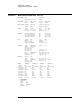
AGILENT 35670A Supplemental Operator’s Guide Section 4: CD Track: CD Track Desc.: Left Ch. (A Out): Right Ch. (B Out): Measuring a Single Channel Spectrum 24 160 kHz Calibration Tone N/A Channel 1 of the AGILENT 35670A Section 5: CD Track: CD Track Desc: Left Ch. (A Out): Right Ch. (B Out): Improving Measurement Results 24 160 kHz Calibration Tone N/A Channel 1 of the AGILENT 35670A Section 6: CD Track: CD Track Desc.: Left Ch. (A Out): Right Ch.
AGILENT 35670A Supplemental Operator’s Guide Section 10: CD Track: CD Track Desc.: Left Ch. (A Out): Right Ch. (B Out): Measuring Dual Channel Spectra and Time Waveforms 41 Current Probe, Tachometer Channel 1 of the AGILENT 35670A Channel 2 of the AGILENT 35670A Section 11: CD Track: CD Track Desc.: Left Ch. (A Out): Right Ch.