Agilent Technologies N5161A/62A/81A/82A/ 83A MXG Signal Generators Installation Guide Agilent Technologies
Notices © Agilent Technologies, Inc. 2006-2009 Warranty No part of this manual may be reproduced in any form or by any means (including electronic storage and retrieval or translation into a foreign language) without prior agreement and written consent from Agilent Technologies, Inc. as governed by United States and international copyright laws. The material contained in this document is provided “as is,” and is subject to being changed, without notice, in future editions.
Contents 1 Safety Information Warnings, Cautions, and Notes . . . . . . . . . . . . . . . . . . . . . . . . . . . . . . . . . . . . . . . . . . . .1 General Safety Considerations . . . . . . . . . . . . . . . . . . . . . . . . . . . . . . . . . . . . . . . . . . . .1 Instrument Markings . . . . . . . . . . . . . . . . . . . . . . . . . . . . . . . . . . . . . . . . . . . . . . . . . . .2 2 Getting Started Checking the Shipment . . . . . . . . . . . . . . . . . . . . . . . . . . . . . . . . . . . . . . .
Contents 4 Regulatory Information Certification . . . . . . . . . . . . . . . . . . . . . . . . . . . . . . . . . . . . . . . . . . . . . . . . . . . . . . . 29 Assistance . . . . . . . . . . . . . . . . . . . . . . . . . . . . . . . . . . . . . . . . . . . . . . . . . . . . . . . . 29 Statement of Compliance. . . . . . . . . . . . . . . . . . . . . . . . . . . . . . . . . . . . . . . . . . . . . . . 29 Compliance with Canadian EMC Requirements . . . . . . . . . . . . . . . . . . . . . . . . . . . . . . .
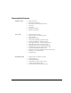
Documentation Overview Installation Guide User’s Guide Programming Guide • • • • • • • Safety Information • • • • • • • • • • • • • • Signal Generator Overview • • • • • • Getting Started with Remote Operation Receiving the Instrument Environmental & Electrical Requirements Basic Setup Accessories Operation Verification Regulatory Information Setting Preferences & Enabling Options Basic Operation Optimizing Performance Using Analog Modulation (Option UNT Only) Using Pulse Modulation (Option UNU On
SCPI Reference Service Guide Key Helpa • • • • • • • • • SCPI Basics • • • • • • Troubleshooting • • Key function description Basic Function Commands LXI System Commands System Commands Analog Modulation Commands Arb Commands Real- Time Commands N5161A/62A/81A/82A SCPI Command Compatibility N5183A SCPI Command Compatibility Replaceable Parts Assembly Replacement Post- Repair Procedures Safety and Regulatory Information Instrument History Related SCPI commands aPress the Help hardkey, and then th
1 Safety Information • Warnings, Cautions, and Notes on page 1 • General Safety Considerations on page 1 • Instrument Markings on page 2 Warnings, Cautions, and Notes The documentation for this product uses the following safety notations. Familiarize yourself with each notation and its meaning before operating the signal generator. WARNING Warning denotes a hazard. It calls attention to a condition or situation that could result in personal injury or loss of life.
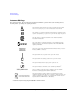
Safety Information Instrument Markings Instrument Markings The signal generator has the following markings. Familiarize yourself with each marking and its meaning before operating the signal generator. The instruction manual symbol. The product is marked with this symbol when it is necessary for you to refer to instructions in the manual. The CE mark is a registered trademark of the European Community. If this symbol is accompanied by a year, it is the year when the design was proven.
2 NOTE Getting Started For the N5161A/62A the softkey menus and features mentioned in this chapter are only available through the Web- Enabled MXG or through SCPI commands. Refer to “Accessing the MXG (ATE) Web- Enabled Page1” on page 7 and to the SCPI Command Reference. The MXG ATE blank front panel models, N5161A and N5162A signal generators, are part of the MXG instrument family and unless otherwise indicated, all references to the MXG are inclusive of the MXG ATE instruments.
Getting Started Checking the Shipment Checking the Shipment 1. Inspect the shipping container for damage. Signs of damage can include a dented or torn shipping container or cushioning material that indicates signs of unusual stress or compacting. 2. Carefully remove the contents from the shipping container and verify that your order is complete.
Getting Started Meeting Environmental and Electrical Requirements Meeting Environmental and Electrical Requirements CAUTION To avoid the loss of data, GPIB settings, or current user instrument states that have not been permanently saved to non- volatile memory, the MXG should always be powered down either via the MXG's front panel power button or the appropriate SCPI command.
Getting Started Meeting Environmental and Electrical Requirements Connecting the AC Power Cord This is a Safety Class 1 Product provided with a protective earth ground incorporated into the power cord. The front panel switch is only a standby switch; it is not a line switch. The AC power cord is the disconnecting device that disconnects the signal generator mains circuits from the mains supply.
Getting Started Configuring the MXG ATE Configuring the MXG ATE NOTE For the N5161A/62A the softkey menus and features mentioned in this guide are only available through the Web- Enabled MXG or through SCPI commands. Refer to Accessing the MXG (ATE) Web- Enabled Page1, the Programming Guide, and to the SCPI Command Reference. The MXG ATE N5161A and N5162A, are blank front panel versions of the N5181A and N5182A.
Getting Started Configuring the MXG ATE Figure 2-1 Web-Enabled MXG ATE2 The Agilent MXG ATE supports LXI Class B* functionality. For more information on the LXI standards, refer to http://www.lxistandard.org/home. *LXI Class B Compliance testing using IEEE 1588-2008 not available at release. To operate the signal generator, click the keys. Note: If you do not see this window, check to see if the window is hidden behind your browser window or your web browser settings are set to block pop-ups.
Getting Started Configuring the Display (N5181A/82A/83A Only) Configuring the Display (N5181A/82A/83A Only)1 Screen saver settings are persistent states; they are unaffected by preset or a power cycle. Use the arrow keys, numeric keypad, or front panel knob to adjust numeric values. Figure 2-2 Display Softkeys Range: 0—100 Range: 35—55 Light Only turns the display light off, leaving the text visible at a low intensity. Light & Text turns the display light and the text off.
Getting Started Configuring for Remote Control Configuring for Remote Control1 LAN Configuration Configuring the LAN Interface NOTES Use a 100Base-T LAN cable to connect the signal generator to the LAN. Use a crossover cable to connect the signal generator directly to a PC. For details on using the instrument remotely, see the Programming Guide. Listed in the Programming Guide For details on a key, press Help and then the desired key.
Getting Started Configuring for Remote Control Enabling LAN Services: Browser, Sockets, and VXI-11 Use a browser to view signal generator files. Use a browser to control the signal generator GPIB Configuration For details on a key, press Help and then the desired key. Select the desired GPIB language. See also the Programming Guide and the SCPI Command Reference. NOTES USB is also available. It is not shown in the menu because it requires no configuration.
Getting Started Ordering Accessories Ordering Accessories You can purchase accessories or documentation at: http://www.agilent.com/find/mxg If you do not have access to the Internet, please contact your Agilent field engineer. See also, “Contacting Agilent” on page 14.
Getting Started Ordering Accessories Descriptiona Part Number Part Numberb Programming Guidec N5180- 90005 n/c Service Guidec N5180- 90006 n/c Document Setc: N5180- 90001 n/c N5180- 90007 n/c • • • • Data Sheet User’s Guide Programming Guide SCPI Reference Documentation CD- ROMc: PDF files: • Documentation Set • Installation Guide • Service Guide Text files: • error messages • programming examples a For a description of the contents of each guide and reference, see page v.
Getting Started Proper Use and Cleaning Proper Use and Cleaning The signal generator cover protects against physical contact with internal assemblies that contain hazardous voltages, but does not protect internal assemblies against contact with liquids. To avoid damage and personal injury, ensure that liquids are positioned away from the signal generator. WARNING Personal injury may result if the signal generator is not used as specified. Unspecified use impairs the protection provided by the equipment.
Operation Verification 3 Operation Verification NOTE For the N5161A/62A the softkey menus and features mentioned in this chapter are only available through the Web- Enabled MXG or through SCPI commands. Refer to “Accessing the MXG (ATE) Web- Enabled Page1” on page 7 and to the SCPI Command Reference.
Operation Verification Running Self Test Running Self Test1 Self Test is a series of internal tests of signal generator functions. If this test fails, refer to “Self Test Failure” on page 17 for further instructions. It takes about 5 minutes to run the self test. Use the following procedure to run self test: 1. Disconnect all external cables, including GPIB, LAN, and USB cables. 2. Preset the signal generator: Press Preset > Utility > Instrument Info > Self Test.
Operation Verification Running Self Test • The current status of the self-test is: Failure. One or more tests have failed. System diagnostics indicate this test as the root failure: xxx If the signal generator fails only one test, the title of the failed test displays. If the signal generator fails more than one test, the test number of the most significant failure (root failure) displays. NOTE The root failure is the error to report to Agilent Support. Refer to “Contacting Agilent” on page 14.
Operation Verification Frequency Range and Accuracy Check Frequency Range and Accuracy Check The frequency range is tested by determining the frequency accuracy relative to the timebase at the frequency limits of the signal generator. This test can be performed with either a frequency counter or a spectrum analyzer.
Operation Verification Frequency Range and Accuracy Check Frequency Counter Procedure (N5161A1/62A1/81A/82A) Test Setup 1. Connect the equipment as shown. 2. Preset the signal generator: Press Preset. 3. Turn modulation off: Press the Mod On/Off so that the MOD On/Off LED turns off. 4. Set the amplitude: Press Amplitude and enter 0 dBm. NOTE 5. Turn RF on: Press RF On/Off so that the RF On/Off LED lights. 6. Verify that the frequency counter is locked to the 10 MHz external reference frequency (±1 Hz).
Operation Verification Frequency Range and Accuracy Check Spectrum Analyzer Procedure (N5161A1/62A1/81A/82A/83A) Test Setup 1. Connect the equipment as shown. 2. Verify that the spectrum analyzer is locked to the 10 MHz external reference frequency. 3. Align the spectrum analyzer: Press System > Alignment > Align All Now. Table 3-3 Frequency Accuracy Limits 4. Preset the signal generator: Press Preset. 5. Turn modulation off: Press the Mod On/Off so that the MOD On/Off LED turns off. 6.
Operation Verification Checking the Output Power Troubleshooting Problems with the Frequency Accuracy Check • Verify the cables are connected correctly. • If you are using a frequency counter, verify that you are using the correct channel for the frequencies you are measuring. • If you are using a spectrum analyzer, verify that the spectrum analyzer is set to external reference. Checking the Output Power This test verifies that the CW output power from the signal generator is within defined limits.
Operation Verification Checking the Output Power N5161A1/81A Test Procedure power meter. b. Select a power meter channel (if applicable). Test Setup 1. Zero and calibrate the power sensor to the power meter: c. Use the arrow keys to enter the frequency at which to measure the power. 9. Measure the output power level. 10. Repeat steps 6 through 9 to measure power at each of the 15 frequencies listed in Table 3- 8. 11. Confirm that the measured power levels are within the limits listed in the table.
Operation Verification Checking the Output Power N5162A1/82A Test Procedure 7. Set the amplitude to 7 dBm: Press Amplitude > 7 > dBm. Test Setup 8. Configure the power meter as follows: 1. Zero and calibrate the power sensor to the power meter: a. On the power meter, press the Frequency Cal Fac button. b. If applicable, select a power meter channel. c. Use the arrow keys to enter the frequency at which to measure the power. 9. Measure the output power level. 10.
Operation Verification Checking the Output Power Table 3-6 With Modulation 11. Preset the signal generator: Press Preset. N5162A/82A Output Power with Modulation 12. Select the factory- supplied waveform SINE_TEST_WFM: Frequency (MHz) a. Press Mode > Dual ARB > Select Waveform. b. Highlight the SINE_TEST_WFM waveform. c. Press Select Waveform. 13. Turn the arbitrary waveform player on: Press the ARB softkey to highlight On. 14.
Operation Verification Checking the Output Power N5183A Test Procedure Table 3- 8. 11. Confirm that the measured power levels are within the limits listed in the table. Test Setup 1. Zero and calibrate the power sensor to the power meter: *Refer to Table 3-7 on page 25 2.
Operation Verification Checking the Output Power Table 3-8 Leveled Output Power Limits N5183A Output Power Frequency 40 GHz (Option 540) Amplitude (dBm) Standard Power Amplitude (dBm) Option 1EA 520 532/ 540 520 -- 7 -- Limitsa b (dB) 532/ 540 12 ±2 a.Limit values are due to power meter uncertainty. b.For questions around measurement uncertainty, refer to the Data Sheet.
Operation Verification Checking the Output Power Troubleshooting Problems with the Output Power Check • Verify that you are using the appropriate power sensor. • Normally, power sensor calibration factors are automatically downloaded to the power meter when the power meter turns on. If this does not occur, manually enter the correct calibration factors for the power sensor you are using. • Verify that the power sensor is properly calibrated to the power meter.
Operation Verification Checking the Output Power 28 Agilent N5161A/62A/81A/82A/83A MXG Signal Generators Installation Guide
4 Regulatory Information Certification Agilent Technologies certifies that this product met its published specifications at the time of shipment from the factory. Agilent Technologies further certifies that its calibration measurements are traceable to the United States National Institute of Standards and Technology, to the extent allowed by the Institute’s calibration facility, and to the calibration facilities of other International Standards Organization members.
Regulatory Information Compliance with German Noise Requirements Compliance with German Noise Requirements This is to declare that this instrument is in conformance with the German Regulation on Noise Declaration for Machines (Laermangabe nach der Maschinenlaermrerordnung - 3.GSGV Deutschland). Acoustic Noise Emission/Geraeuschemission LpA < 70 dB LpA < 70 dB Operator position am Arbeitsplatz Normal position normaler Betrieb per ISO 7779 nach DIN 45635 t.
Index A AC power cord, connecting, 6 symbol, 2 accessories, 12 address, GPIB, 11 Agilent, contacting, 14 alcohol, cleaning with, 14 altitude requirements, 5 Australian Communications Authority (C- tick) mark, 2 auto- IP, 10 IEC Publication 61010, 29 inspection, shipping container, 4 instrument warm up, 15 interface, GPIB, 11 interface, LAN, 10 IP address, setting, 10 ISM1- A symbol, 2 L LAN configuration, 10 line setting requirements, 5 LXI standard specifications symbol, 2 B brightness adjustment, 9 C
Index sockets, enabling, 11 standby symbol, 2 T temperature requirements, 5 troubleshooting output power, 21 V ventilation requirements, 5 verification, operation, 15 voltage requirements, 5 VXI- 11, enabling, 11 W warnings, 1 web server, 11 weight, signal generator, 4 32 Agilent N5161A/62A/81A/82A/83A MXG Signal Generators Installation Guide