Service Manual Agilent Model 66332A Dynamic Measurement DC Source and Agilent Model 6632B, 6633B, 6634B System DC Power Supply For instruments with Serial Numbers: Agilent 66332A: US37470791 and up Agilent 6632B: US37471966 and up Agilent 6633B: US37470746 and up Agilent 6634B: US37470655 and up For instruments with higher serial numbers, a change page may be included. Agilent Part No. 5962-8119 Microfiche No 6962-8120 Printed in U.S.A.
Warranty Information CERTIFICATION Agilent Technologies certifies that this product met its published specifications at time of shipment from the factory. Agilent Technologies further certifies that its calibration measurements are traceable to the United States National Bureau of Standards, to the extent allowed by the Bureau's calibration facility, and to the calibration facilities of other International Standards Organization members.
Safety Summary The following general safety precautions must be observed during all phases of operation of this instrument. Failure to comply with these precautions or with specific warnings elsewhere in this manual violates safety standards of design, manufacture, and intended use of the instrument. Agilent Technologies assumes no liability for the customer's failure to comply with these requirements. WARNING Servicing instructions are for use by service-trained personnel.
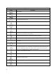
Safety Symbol Definitions Symbol Description Direct current Alternating current Both direct and alternating current Three-phase alternating current Earth (ground) terminal Protective earth (ground) terminal Frame or chassis terminal Terminal is at earth potential (Used for measurement and control circuits designed to be operated with one terminal at earth potential.
Notice The information contained in this document is subject to change without notice. Agilent Technologies makes no warranty of any kind with regard to this material, including but not limited to, the implied warranties of merchantability, and fitness for a particular purpose. Agilent Technologies shall not be liable for errors contained herein or for incidental or consequential damages in connection with the furnishing, performance or use of this material.
Table of Contents Warranty Information Safety Summary Notice Printing History Instrument Identification Table of Contents INTRODUCTION Organization Safety Considerations Related Documents Revisions Manual Revisions Firmware Revisions Electrostatic Discharge VERIFICATION AND PERFORMANCE TESTS Introduction Test Equipment Required Measurement Techniques Setup for Most Tests Electronic Load Current-Monitoring Resistor Operation Verification Tests Performance Tests Programming Constant Voltage (CV) Tests CV Se
Power-on Self-test Failures CV/CC Status Annunciators Troubleshooting Bias and Reference Supplies J307 Voltage Measurements Manual Fan Speed Control Disabling Protection Features Post-repair Calibration Inhibit Calibration Switch Calibration Password Initialization ROM Upgrade Identifying the Firmware Upgrade Procedure Disassembly Procedures List of Required Tools Cover, Removal and Replacement A2 Interface Board, Removal and Replacement Front Panel Assembly, Removal and Replacement A3 Front Panel Board, Re
1 Introduction Organization This manual contains information for troubleshooting and repairing to the component level the Agilent Model 66332A Dynamic Measurement DC Source and the Agilent Model 6632B, 6633B, 6634B System DC Power Supplies. Hereafter all models will be referred to as the dc power supply.
1 - Introduction Revisions Manual Revisions This manual was written for dc power supplies that have the same manufacturing dates (the first four digits) as those listed on the title page and whose unique identification number (the last four digits) are equal to or higher than those listed in the title page.
2 Verification and Performance Tests Introduction This document contains test procedures to verify that the dc power supply is operating normally and is within published specifications. There are three types of tests as follows: Built-in Self Tests These tests, run automatically when the power supply is turned on, check most of the digital circuits and the programming and readback DACs.
2 - Verification and Performance Tests Resistor (substitute for electronic load if load is too noisy for CC PARD test) 1 ohm, 50 W 3 ohm, 100 W (Agilent 66332A/6632B) 24 ohm, 100 W (Agilent 6633B) 99 ohm, 100 W (Agilent 6634B) 1k ohm, 5%, 3W (all models) Ohmite L50J1R0 Ohmite RLS5R0 (adjustable) Ohmite RLS25R (adjustable) Ohmite RLS100 (adjustable) Agilent 0813-0001 Oscilloscope Sensitivity: 1 mV Bandwidth Limit: 20 MHz Probe: 1:1 with RF tip Agilent 54504A or equivalent RMS Voltmeter True RMS Bandwi
Verification and Performance Tests - 2 Electronic Load Many of the test procedures require the use of a variable load capable of dissipating the required power. If a variable resistor is used, switches should be used to either; connect, disconnect, or short the load resistor. For most tests, an electronic load can be used. The electronic load is considerably easier to use than load resistors, but it may not be fast enough to test transient recovery time and may be too noisy for the noise (PARD) tests.
2 - Verification and Performance Tests Table 2-2. Programming Ratings Model Voltage Rating Full Scale Rating Current Rating Full Scale Rating Agilent 66332A/6632B 20 V 20.020 V 5A 5.0045 A 50 V 50.045 V 2A 2.002 A Agilent 6633B 100 V 100.1 V 1A 1.001 A Agilent 6634B Constant Voltage (CV) Tests CV Setup If more than one meter or if a meter and an oscilloscope are used, connect each to the terminals by a separate pair of leads to avoid mutual coupling effects.
Verification and Performance Tests - 2 e. Open the load and again record the DVM voltage reading. The difference between the DVM readings in steps (d) and (e) is the load effect voltage, and should not exceed the value listed in the performance test record chart for the appropriate model under CV LOAD EFFECT. CV Source Effect This test measures the change in output voltage that results from a change in ac line voltage from the minimum to maximum value within the line voltage specifications. a.
2 - Verification and Performance Tests Transient Recovery Time This test measures the time for the output voltage to recover to within the specified value following a 50% change in the load current. Loading Transient tttt t v t v Unloading Transient Figure 2-2. Transient Waveform a. Turn off the supply and connect the output as in Figure 2-1a with the oscilloscope across the +S and the -S terminals. b.
Verification and Performance Tests - 2 e. Divide the voltage drop (DVM reading) across the current monitoring resistor by its resistance to convert to amps and record this value (Iout). Also, record the current reading that appears on the front panel display. The readings should be within the limits specified in the performance test record card for the appropriate model under CC PROGRAMMING @ FULL-SCALE. Current Sink (-CC) Operation This test verifies current sink operation and readback. a.
2 - Verification and Performance Tests c. Set up voltmeter to take measurements in the statistical mode as follows: Press Shift key, f0, Shift key, N Press ^ (up arrow) until MATH function is selected, then press >. Press ^ (up arrow until STAT function is selected then press (ENTER). d. Set up voltmeter to read the average of the measurements as follows: Press Shift key, f1, Shift key, N. Press down arrow until RMATH function is selected, then press >.
Verification and Performance Tests - 2 CC Noise (PARD) Periodic and random deviations (PARD) in the output combine to produce a residual ac current, as well, as an ac voltage superimposed on the dc output. Constant current (CC) PARD is specified as the rms output current in a frequency range 20 Hz to 20 Mhz with the supply in CC operation. a. Turn off the supply and connect the load, monitoring resistor, and rms voltmeter across the monitoring resistor as shown in Figure 2-1a.
2 - Verification and Performance Tests Performance Test Record Forms Model Agilent 66332A OR Agilent6632B Test Description Report No _______________ Date __________________ Minimum Specs. Results* Maximum Specs. Measurement Uncertainty − 10 mV __________ + 10 mV 1.6 µV Front Panel Display Readback Vout − 3 mV __________ Vout + 3 mV 1.6 µV High Voltage (Full Scale) Vout 19.980 V __________ 20.
Verification and Performance Tests - 2 Model Agilent 6633B Test Description Report No _______________ Date __________________ Minimum Specs. Results* Maximum Specs. Measurement Uncertainty − 20 mV __________ + 20 mV 1.7 µV Front Panel Display Readback Vout − 6 mV __________ Vout + 6 mV 1.7 µV High Voltage (Full Scale) Vout 49.955 V __________ 50.045 V 717.5 µV Front Panel Display Readback Vout − 21 mV __________ Vout + 21 mV 717.5 µV − 4 mV __________ + 4 mV 35 µV − 1.
2 - Verification and Performance Tests Model Agilent 6634B Test Description Report No _______________ Date __________________ Minimum Specs. Results* Maximum Specs. Measurement Uncertainty − 50 mV __________ + 50 mV 2.1 µV Front Panel Display Readback Vout − 12 mV __________ Vout + 12 mV 2.1 µV High Voltage (Full Scale) Vout 99.9 V __________ 100.1 V 1.4 mV Front Panel Display Readback Vout − 42 mV __________ Vout + 42 mV 1.
3 Troubleshooting Introduction WARNING: SHOCK HAZARD. Most of the troubleshooting procedures given in this chapter are performed with power applied and protective covers removed. Such maintenance should be performed only by service trained personnel who are aware of the hazards (for example, fire and electrical shock). CAUTION: This instrument uses components which can either be damaged or suffer serious performance degradation as a result of ESD (electrostatic discharge).
3 - Troubleshooting Test Equipment Required Table 3-1 lists the test equipment required to troubleshoot the power supply. Recommended models are listed. Table 3-1.
Troubleshooting - 3 Turn on unit and observe the display. Unit should display all of the segments and annunciators, the address and then after self test display either an error message or go to the metering mode. Display comes on? No Yes Error Message? Yes +5V @ A3J2-8? Yes A3J2-5 held low? No Yes Troubleshoot A1 +5V Interface Bias circuit, W6 or W7.
3 - Troubleshooting Continued from sheet 1 Program Voltage and Current full scale, enable output with no load. Measure Voltage at output terminals. Display and measured voltage OK? No No Yes Current close to programmed value? Yes Program OV below output voltage Calibrate Current No Output Voltage near zero? No No If output is OK but meter wrong, replace A2. If in CC but both are off, check gain of Current Monitor Amplifiers and Monitor Resistor R403/473 values.
Troubleshooting - 3 Figure 3-1 Sheet 3.
3 - Troubleshooting Connect a DC coupled scope set to 1mS/20V/ div across the output and turn on the supply while observing the scope for a momentary pulse greater than the supply rating Does the supply overshoot? Yes Go to “Troubleshooting High Output Voltage” (sheet 7) No Disable the OV circuit as described in paragragh "Disabling Protection Features" Output @ zero volts? No Yes 4V @ A1R350-2? No A2 or W7 Defective No Check C336, R356, R351, R349(1-2) and U306B No Check C335, R354, R350(1-2
Troubleshooting - 3 Continued from sheet 4 Connect a DC coupled scope across the output and press Protect Clear several times while observing the scope Pulses high? Yes Go to "Troubleshooting High Output Voltage" (sheet 12) No A1U306B-2, OV_Detect*, High? No U306B-8 3.8V? No Check OV_Prog, Imon_Comp, C335, R350, R354 Yes A1R438, OV_SCR*, +0.
3 - Troubleshooting Program output on, voltage and current full scale then check output voltage FS Prot off and Output OK? Yes Calibrate unit Yes Go to "Troubleshooting High Output Voltage" (sheet 12) No Troubleshoot Fuse divider and amplifier circuit (R393/394, U305) No Disable the protection feature by simultaneously pressing the 0 and 9 keys, press the ^ key until the display reads "No Protect Off", press the Up Arrow to display "No Protect On" then press enter Output V > programmed value? No
Troubleshooting - 3 Program full scale voltage and current and enable output. Measure output voltage with an external voltmeter. Display zero V but output OK? Yes Check W7 (Vmon) and A2, Interface board Yes CC? No CV or CC Annunciator on? Yes No No Displays current equal to prog value? Check for short across output such as output cap C382, CR342, etc. No Check W7, A2 Interface Board Yes Check Positive Current Control Circuit, U310B No Go To sheet 9 CC_Prog, R360 -4.7V ? Q305A base -11.
3 - Troubleshooting Continued from sheet 7 Q302 base -5V ? No Check C330, R333, R346, and Q302 Yes Check +Rail and Output Stage No Check Q301, Q305 circuits No Check Q302, Q307, R324 and R326 Yes Q303 base >1.2V (meas. from +Out) ? No >1V across R323 ? Yes Q307 collector to emitter 4V? Yes Check C331, C333, C339 and Q306 circuits Figure 3-1 Sheet 8.
Troubleshooting - 3 Continued from sheet 7 CV_Prog @ R401 -4.
3 - Troubleshooting Continued from sheet 2 CC_Prog, R360, -4.8V ? No Check A2 Interface Board Yes Imon_H, U309A-6 ~+3.5V ? Yes Check Positive Current Control Circuit No Drop across R473 ~0.25V ? No Check R473 Yes Check High Range Current Monitor Amplifier Figure 3-1 Sheet 10.
Troubleshooting - 3 Program the output voltage and current to the full scale value and the OV to 1/2.
3 - Troubleshooting Disable the OV capability by shorting R351. After the protection is disabled, program the output voltage to zero, current to full scale and Output ON. If the unit is in "Protect" mode, Press Protect Clear. The output should now go high and not trip the OV. Is the CV annunciator on ? No * V_mon should be approximately 6632B or 66332A Vout/4.25 6633B Vout/10.
Troubleshooting - 3 Specific Troubleshooting Procedures Power-on Self-test Failures The power-on self-test sequence tests most of the digital and DAC circuits. If the supply fails self-test, the display "ERR" annunciator will come on. You can then query the unit to find out what the error(s) are. When an error is detected, the output is not disabled so you can still attempt to program the supply to help troubleshoot the unit. Table 3-2 lists the self test errors and gives the probable cause for each error.
3 - Troubleshooting CV/CC Status Annunciators Troubleshooting The CV/CC annunciators are particularly helpful when troubleshooting a unit with no output. If the unit has no output voltage or current and one of the annunciators is on then the problem is in the control circuit associated with that annunciator. An example of how this might be useful would be in a case where the voltage and current are programmed to some positive value, there is no output voltage and the CV annunciator is on.
Troubleshooting - 3 J307 Voltage Measurements J307 connects the A1 Main Board Assembly to the A2 Interface Assembly. Table 3-4 provides a quick method of determining if the voltages between these assemblies are within the normal range. If any of these voltages is outside the normal range, refer to the flowcharts to further troubleshoot the circuit associated with the abnormal voltage. Table 3-4.
3 - Troubleshooting Manual Fan Speed Control Under some circumstances such as testing acoustical devices where the fan noise would interfere with the test, it would be advantageous to reduce the fan speed. If the test requires a very light load, the ambient temperature is low and the duration of the test is short, the fan speed may be temporarily reduced. The turn-on default is "Automatic" so this procedure must be performed, as needed, every time the line voltage is turned on.
Troubleshooting - 3 Post-repair Calibration Calibration is required annually and whenever certain components are replaced. If components in any of the circuits listed below are replaced, the supply must be re-calibrated as described in Appendix B of the User's Guide. a. A1 Control Board: Voltage or Current Monitor Amplifier circuits, High Bandwidth Current Amplifier, or Current Monitor resistors R403/R473 b.
3 - Troubleshooting Initialization The dc power supply's GPIB address and model number as well as other constants which are required to program and calibrate the supply are stored in a EEPROM on the A2 Interface board. The Interface board also contains references and other components that will affect the alignment of the supply. If the Interface board is replaced, the supply must be reinitialized and calibrated. To initialize the power supply: a. Enable the Calibration mode b.
Troubleshooting - 3 Disassembly Procedures The following paragraphs provide instructions on how to disassemble various components of the dc power supply. Once disassembled, the components can be reassembled by performing the disassembly instructions in reverse order. Figure 3-2 shows the location of the major components of the unit. Figure 3-2. Component Location WARNING: SHOCK HAZARD.
3 - Troubleshooting Cover, Removal and Replacement a. Using a 2TP Pozi screwdriver, unscrew the two screws that hold the carrying straps to the power supply, and then remove the two screws from the opposite side of the case. b. To remove the cover, first spread the bottom rear of the cover slightly and push from the front panel c. Slide the cover backward until it clears the rear of the power supply. A2 Interface Board, Removal and Replacement To remove the Interface Board, proceed as follows: a.
Troubleshooting - 3 S1 Line Switch, Removal and Replacement a. First remove the front panel assembly as described under “Front Panel Assembly, Removal and Replacement.” b. Release the switch from the front panel by pressing the locking tabs inward against the body of the switch and pushing the switch out of its opening. NOTE: When reinstalling the switch, make sure that the letter “O” is facing up when the switch is installed in its opening.
3 - Troubleshooting Line Voltage Wiring Figure 3-3 illustrates the primary wiring configuration of the power transformer for various ac line voltages. Use long nose pliers to disconnect the wires going to the transformer terminals.
4 Principles of Operation Introduction This section describes the different functional circuits used in the dc power supply models covered in this manual. First, the I/O external signals that connect to the Agilent power supply are described. Next, the overall block diagrams for the dc power supply are described in detail. The simplified block diagrams in this section show the major circuits on the dc power supply as well as the signals between circuits.
4 - Principles of Operation A3 Front Panel Circuits As shown in Figure 4-1, the supply's front panel assembly contains a circuit board, a keypad, a liquid crystal display (LCD), and a rotary control (RPG) for the output voltage and current. With the exception of the RPG (A3G1), the A3 Front Panel board is an assembly-level replaceable part. A separate front panel binding post board is also included on the unit. It is also available as an assembly-level replaceable part.
Principles of Operation - 4 Figure 4-1.
4 - Principles of Operation The EEPROM (electrically erasable programmable read-only memory) chip on the A2 interface board stores a variety of data and configuration information. This information includes calibration constants, GPIB address, present programming language, and model-dependent data, such as the minimum and maximum values of voltage and current. One of the EEPROM storage locations holds a checksum value which is used to verify the integrity of the EEPROM data.
Principles of Operation - 4 Figure 4-2.
4 - Principles of Operation Two current shunt resistors monitor the output current. RmHi (R473) monitors the high current range; RmLo (R403) monitors the low current range. Shunt clamps, connected in parallel across RmLo, turn on at approximately 25 mA to limit the voltage drop at high currents. The Range_Select signal sets the level at which switching occurs. The output of the current monitor drives the level.
Principles of Operation - 4 The output is programmed off. An overvoltage condition is detected (OV_Detect* signal is received). The line voltage falls below 90 volts (approximately). Current readback is provided by three separate circuits. The previously discussed high range current signal (Imon_H) returns the high range current measurement. When the unit is operating in the low current readback mode, a separate low range current shunt and amplifier provides low-current readback via the Imon_L signal.
5 Replaceable Parts List Introduction This section lists the replaceable parts for Agilent Models 66332A, 6632B, 6633B, and 6634B power supplies. Refer to Figures 5-1 for the location of mechanical parts with the reference designators MP. Refer to the board location diagrams in Chapter 6 for the location of electrical parts. Designator A1 A1 A1 A2 A2 A3 A4 A4 A5 A6 B1 T1 T1 T1 S1 W1 W2 W3 W4 W5 W6 W7 W10 W11 W15 Table 5-1.
5 - Replaceable Parts Designator MP1 MP2 MP2 MP3 MP4 MP5 MP6 MP6 MP6 MP6 MP7 MP8 MP9 MP10 MP11 MP12 MP13 MP14 MP15 MP16 MP17 MP18 MP19 MP20 MP21 MP22 MP23 MP24 MP25 MP26 MP27 MP28 MP29 MP30 MP31 MP32 MP33 MP34 MP35 MP36 MP37 MP38 MP39 MP40 MP41 MP42 56 Model All All All All All All 66332A 6632B 6633B 6634B All All All All All All All All All All All All All All All All All All All All All All All All All All All All All All All All All All All All All All Table 5-2.
Replaceable Parts - 5 Figure 5-1.
5 - Replaceable Parts Designator A1 A1 A1 C300 C301 C303 C303 C303 C304 C305 C306 C307 C308, 309 C310 C311, 312 C313 C313 C313 C314 C315, 316 C317 C318, 319 C320 C321 C322 C323 C324 C325 - 327 C328 C330 C331, 332 C333 C334 C334 C335 C335 C335 C336 C337 - 339 C340 C341 - 343 C344 C344 C345 C346 C346 C347 C348 58 Table 5-3.
Replaceable Parts - 5 Designator C349 C349 C350 C351 C352 C352 C353, 354 C355 C355 C356 C357 C358 C359 C359 C360 C360 C360 C361 C362 C362 C362 C363 C364 C365 C366, 367 C368 C369 C370 C371 C372, 373 C374 C375 C375 C376 C376 C376 C377 C377 C377 C378 C379 C380 C381 C382 C382 C382 C383 C384 C386 Model 66332A/6632B 6633B/6634B All All 66332A/6632B 6633B/6634B All 66332A/6632B 6633B/6634B All All All 66332A/6632B 6633B/6634B 66332A/6632B 6633B 6634B 66332A/6632B 66332A/6632B 6633B 6634B All All All All All All A
5 - Replaceable Parts Designator C403 C405 C411 C420 C421 C422 C422 C423 C423 C424 C424 C425 C426 C427 C428 - 430 C431, 432 C480, 481 C482 C496, 497 C498 C499 CR342 Model 66332A/6632B All 6633B/6634B 6633B/6634B 6633B/6634B 6633B 6634B 6633B 6634B 6633B 6634B 6633B/6634B 6634B 6634B 6633B/6634B 6633B All 6633B/6634B All All 66332A/6632B 66332A/6632B CR342 6633B CR342 6634B D300 - 303 D304 D305, 306 D307 D308 All All All All 66332A/6632B D308 D309 6633B/6634B 66332A/6632B D309 D310 6633B/6634B 663
Replaceable Parts - 5 Designator D310 D311 D311 D312 D313, 314 D315 D316 D317 D317 D318 D318 D319 - 321 D322 D323, 324 D325 D326 D327, 328 D329 D330 D335 D336, 337 D400 D470, 471 D499 F300, 301 F302 F302 F303 F303 F304 F305 F305 Model 6633B/6634B 66332A/6632B 6633B/6634B All All All All 66332A/6632B 6633B/6634B 66332A/6632B 6633B/6634B 6633B/6634B All All All All All All 66332A/6632B/6633B 66332A/6632B All 6634B All 66332A/6632B/6633B All 66332A/6632B/6633B 6634B 66332A/6632B/6633B 6634B All 66332A/6632B
5 - Replaceable Parts Designator Q300 Q301 Q301 Q302 Q302 Q303 Model All All All 66332A/6632B/6633B 6634B 66332A/6632B/6633B 6634B 66332A/6632B Q303 6633B Q303 6634B Q304 66332A/6632B Q304 6633B Q304 6634B Q305 Q306 Q307 Q308 Q308 Q309 Q309 Q310 Q310 Q311 Q311 Q312 Q313 All All All 66332A/6632B 6633B/6634B 66332A/6632B 6633B/6634B 66332A/6632B 6633B/6634B 66332A/6632B 6633B/6634B 66332A/6632B All All All All All All All All All All Q314 62 Part Number 5060-3245 1854-0828 1205-0282 1854-0474
Replaceable Parts - 5 Designator Q315 Q315 Q316 Q317 Q317 Q318 Q319 R300 R300 R301 R301 R301 R302 R302 R302 R303 R304 R305 R306 R307 - 309 R310 R311 R312 R313 R313 R314 R315 R316 R317, 318 R319 R319 R319 R320 R320 R320 R321 R321 R321 R322 R323 R323 R323 R324 R324 R325 R325 R325 Model 66332A/6632B 6633B/6634B All 66332A/6632B 6633B/6634B All 66332A/6632B 66332A/6632B/6633B 6634B 66332A/6632B 6633B 6634B 66332A/6632B 6633B 6634B All All All All All All All All 66332A/6632B 6633B/6634B All All All All 66332A/
5 - Replaceable Parts Designator R326 R326 R327 R328 R328 R329 R329 R329 R330 R330 R331 R332 R333 R333 R334 R335 R336 R337 R337 R339 R339 R339 R340 R340 R340 R341 R341 R341 R342 R342 R342 R343 R343 R343 R344 R345 R346 R347 R348 R348 R348 R349 R349 R349 R350 R350 R350 64 Model 66332A/6632B 6633B/6634B All 66332A/6632B 6633B/6634B 66332A/6632B 6633B 6634B 66332A/6632B 6633B/6634B All All 66332A/6632B 6633B/6634B 66332A/6632B All All 66332A/6632B/6633B 6634B 66332A/6632B 6633B 6634B 66332A/6632B 6633B 6634B
Replaceable Parts - 5 Designator R351 R351 R351 R352 R353 R354 R354 R354 R355 R356 R356 R356 R357 R357 R358 R359 R360, 361 R362 R362 R363 R364 R364 R365, 366 R367 R370 R371 R371 R372 R372 R373 R374 R375 R376 R376 R377 R377 R378 R378 R379 R380 R381 R382 R383 R384 R384 R385 R385 Model 66332A/6632B 6633B 6634B 66332A/6632B All 66332A/6632B 6633B 6634B All 66332A/6632B 6633B 6634B 66332A/6632B 6633B/6634B All 66332A/6632B All 66332A/6632B 6633B/6634B All 66332A/6632B 6633B/6634B All All All 66332A/6632B 6633B/
5 - Replaceable Parts Designator R386 R386 R387 R387 R388 R389 R389 R390, 391 R392 R392 R393 R393 R394 R394 R394 R395, 396 R397 R398 R399 R400, 401 R402 R403 R404 R405 R406 R407 R407 R408 R408 R409 R409 R410 R410 R411 R412 R412 R413 R414 R415 R415 R416 R417 R418 R418 R418 R419 R420 66 Model 66332A/6632B 6633B/6634B 66332A/6632B 6633B/6634B All 66332A/6632B 6633B All 66332A/6632B 6633B/6634B 66332A/6632B/6633B 6634B 66332A/6632B 6633B 6634B All 6634B All All All All All 66332A/6632B All All 66332A/6632B 66
Replaceable Parts - 5 Designator R421 R421 R422 R423 R423 R425 R427 R427 R428 R429 R429 R430 R431 R432 R432 R432 R433 R434 R435 R436, 437 R438 R439 R440 R440 R441 R442 R442 R442 R443 R443 R443 R444 R445 R445 R445 R446 R446 R446 R447 R448 R449 R450 R451 R452 R452 R452 R453 R454 Model 66332A/6632B 6633B 66332A/6632B 66332A/6632B/6633B 6634B 66332A/6632B 66332A/6632B 6633B/6634B 6634B 66332A/6632B/6633B 6634B 66332A/6632B All 66332A/6632B 6633B 6634B 66332A/6632B 66332A/6632B All 66332A/6632B All 66332A/6632B
5 - Replaceable Parts Designator R455 R455 R455 R456 R457 R458 R459 R460 R461 R462 R462 R463 R464, 465 R466 R466 R466 R467, 468 R469 R469 R470 R470 R471 R471 R472 R473 R473 R473 R474 R476 R477 R478, 479 R480, 481 R482 R483 R488 R488 R488 R489 R489 R489 R490 R490 R490 R493 R494, 495 R496 R496 68 Model 66332A/6632B 6633B 6634B All 66332A/6632B All 66332A/6632B All All 66332A/6632B/6633B 6634B 6634B All 66332A/6632B 6633B 6634B 66332A/6632B 66332A/6632B 6633B 66332A/6632B 6633B/6634B 66332A/6632B 6633B/6634B
Replaceable Parts - 5 Designator R497 R497 R498 - 500 R505 R510 - 517 R520 R521 R522 RT301 S300 T300 T300 U300 U301 U302 U303 U304 U305 U306 U308 U309 U310 U311 U313 U314 U315 U400 VR300 VR301 VR302 VR303 VR303 VR304 VR304 VR305 VR305 VR335 VR335 W300, 301 Model 66332A/6632B 6633B/6634B All 6633B 66332A/6632B 6633B/6634B All All All All 66332A/6632B 6633B/6634B All All All All All All All All All All All All All All All All All All All All 66332A/6632B All All All All 6634B 66332A/6632B 6633B/6634B 663
5 - Replaceable Parts A2 Interface PCA, Tested for 66332A A2 Interface PCA, Tested for 6632B/6633B/6634B A3 Front Panel PCA Tested for all models 5063-3439 5063-3429 5063-3432 No user replaceable parts No user replaceable parts No user replaceable parts Designator A4 A4 C603, 604 J615 MP5 MP26 MP25 MP24 W15 Table 5-4.
6 Diagrams Introduction This chapter contains drawings and diagrams for troubleshooting and maintaining the Agilent Model 66332A Dynamic Measurement DC Source and the Agilent Model 66332A/6632B/6633B/6634B System DC Power Supplies. Unless otherwise specified in the drawings, a drawing or diagram applies to all models and input voltage options. General Schematic Notes a Components marked with an asterisk are model dependent (See Table 6-1). a All resistors are in ohms 1%, 1/8 W, unless otherwise specified.
6 - Diagrams Table 6-1. Model-dependent Components (continued) Designator R319 R320 R321 R323 R324 R325 R326 R328 R329 R330 R333 R334 R337 R339 R340 R341, 343 R342 R348 R349 R350 R351 R352 R354 R356 R357 R359 R362 R364 R371 R372 R373 R376 R377 R378 R384, 389 R385 R386, 387 R392 R393 R394 R397 R404 R407, 410 R408, 409 R411 R412 72 66332A/ 6632B 316 Ohm 1.5K 80.6K 1K 1K 1K 5.62K 20K 4.7 Ohm 1K 5.11K 0 Ohm 316 Ohm 10K 200 Ohm 215 Ohm 80.6K 316 Ohm 26.1K 3.16K 5K 0 Ohm 16.2K 200K 25K 0 Ohm 39K 25K 35.65K 2.
Diagrams - 6 Table 6-2. A1 Board Component Locations Ref. C300 C301 C302 C304 C307 C308 C309 C311 C312 C314 C315 C316 C317 C318 C319 C320 C321 C322 C323 C324 C326 C327 C328 C329 C330 C331 C332 C333 C334 C335 C336 C337 C338 C339 C340 C341 C342 C343 C344 C345 C346 C347 C348 C349 C350 C351 C352 C353 C354 C355 C356 C357 C358 C359 C360 C361 C362 C363 C364 C365 C366 C367 C368 C369 C370 X 8.125 2.075 7.5 6.025 5.45 4.05 8.025 4.775 4.875 3.5 3.825 3.625 1.15 0.95 3.525 4.8 3.975 5.4 5.4 2.45 0.175 1.15 0.475 0.
6 - Diagrams Table 6-2 continued Ref. R434 R435 R436 R437 R438 R439 R440 R441 R442 R443 R444 R445 R446 R447 R448 R449 R450 R451 R452 R453 R454 R455 R456 R457 R458 R459 R460 R461 R462 R463 R464 R465 R466 R467 R468 R469 R470 R471 R472 R473 R474 R476 R477 R478 R479 R480 R481 R482 R483 R484 R485 R486 R487 R488 R489 R490 R493 R494 R495 R496 R497 R498 R499 74 X 2.5 2.4 7.05 6.8 4.675 1.925 5.7 5.05 0.35 0.2 4.375 3.425 0.9 2.4 1.95 1.95 1.925 0.825 1.95 2.375 1.35 0.075 1.225 1.125 2.2 2.1 0.6 4.675 4.675 8.
Figure 6-1.
Figure 6-2.
Figure 6-3.
Figure 6-3.
Figure 6-3.
Figure 6-4.
Index —+— CV_Detect*, 48, 52 CV_Prog, 50, 52 +OUT, 47 +sense, 47 —D— —A— A1 board removal, 45 A1 Main board, 50 A2 board removal, 44 A2 Interface Board, 48 A2S201, 50 A3 board removal, 45 A3 Front Panel, 48 ADC, 48 —B— DAC, 48 disable protection, 40 disassembly - tools, 43 disassembly procedure, 43 downprogramming, 50, 52 DP_Control, 50 —E— EEPROM, 50 electronic load, 13 electrostatic discharge, 10 error codes, 37 bias voltages, 38, 39 —F— —C— cal denied, 41 calibration, 41 calibration - post repa
Index —J— RS-232, 47 J307 voltages, 39 —S— —L— line voltage wiring, 46 —M— manual revisions, 10 —N— notice, 5 —O— -OUT, 47 out of range, 41 OV_Detect*, 48, 52 OV_Prog, 50 OV_SCR*, 48, 52 —T— —P— PARD, 15, 19 password, 41 performance test form, 19 performance tests, 13 PM_Inhibit, 52 power-on self-test, 37 primary interface, 48 printing, 5 programming, 13 protection, 40 —R— readback accuracy, 14 reference voltages, 38, 39 replaceable parts - binding posts, 57 replaceable parts - chassis, 55 revisi