Agilent 35670A Service Guide Agilent Part Number 35670-90066 Printed in Malaysia Print Date: March 2001 Copyright © Agilent Technologies, Inc., 1992-1995,2000, 2001. All rights reserved. 8600 Soper Hill Road Everett, Washington 98205-1209 U.S.A.
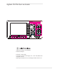
The Agilent 35670A at a Glance (Front Panel)
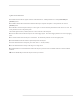
Agilent 35670A Front Panel 1-Use the softkeys to select items from the current menu. A softkey’s function is indicated by a video label on the analyzer’s screen. Throughout this book, softkeys are printed like this: [FFT ANALYSIS]. Hardkeys are front-panel buttons whose functions are always the same. They have a label printed directly on the key itself. Throughout this book, hardkeys are printed like this: [Inst Mode]. 2-The analyzer’s screen is divided into the menu area and the display area.
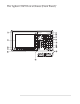
The Agilent 35670A at a Glance (Rear Panel)
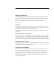
Agilent 35670A Rear Panel 1-The GPIB connector links the Agilent 35670A to other GPIB devices. GPIB parameters are set in the [Local/GPIB] and [Plot/Print] menus. 2-The SERIAL PORT and the PARALLEL PORT link the analyzer to plotters and printers. These parameters are set in the [Plot/Print] menu. 3-The SOURCE connector outputs the analyzer’s source signal. An LED on the front panel indicates if the source is on or off. The source parameters are set in the [Source] menu.
Saftey Summary The following general safety precautions must be observed during all phases of operation of this instrument. Failure to comply with these precautions or with specific warnings elsewhere in this manual violates safety standards of design, manufacture, and intended use of the instrument. Agilent Technologies, Inc. assumes no liability for the customer’s failure to comply with these requirements. GENERAL This product is a Safety Class 1 instrument (provided with a protective earth terminal).
FUSES Only fuses with the required rated current, voltage, and specified type (normal blow, time delay, etc.) should be used. Do not use repaired fuses or short-circuited fuse holders. To do so could cause a shock or fire hazard. DO NOT OPERATE IN AN EXPLOSIVE ATMOSPHERE Do not operate the instrument in the presence of flammable gases or fumes. DO NOT REMOVE THE INSTRUMENT COVER Operating personnel must not remove instrument covers.
Safety Symbols Warning, risk of electric shock Caution, refer to accompanying documents Alternating current Both direct and alternating current Earth (ground) terminal Protective earth (ground) terminal Frame or chassis terminal Terminal is at earth potential. Standby (supply).
Accessories The accessories listed in the following table are supplied with the Agilent 35670A.
In This Book This guide provides instructions for installing, verifying performance, and repairing the Agilent 35670A Dynamic Signal Analyzer. Chapter 1, ‘’Specifications,’’ lists the specifications for the Agilent 35670A and the specifications for the required test equipment. Chapter 2, ‘’Preparing the Analyzer for Use,’’ provides step-by-step instructions for getting the analyzer ready to use and instructions on cleaning the screen, storing, and transporting.
Table of Contents 1 Specifications Frequency 1-3 Single Channel Amplitude 1-4 FFT Dynamic Range 1-5 Input Noise 1-6 Window Parameters 1-6 Single Channel Phase 1-6 Cross Channel Amplitude 1-7 Cross Channel Phase 1-7 Input 1-8 Time Domain 1-9 Trigger 1-9 Tachometer 1-10 Source Output 1-11 Digital Interfaces 1-12 General Specifications 1-13 Order Tracking — Option 1D0 1-14 Swept Sine Measurements —Option 1D2 1-15 Arbitrary Waveform Source—Option 1D4 1-15 Real Time Octave Analysis — Option 1D1 1-16 Recommended
2 Preparing the Analyzer for Use To do the incoming inspection 2-5 To install the analyzer 2-7 To connect the analyzer to a dc power source 2-8 To change the fuses 2-10 To connect the analyzer to a serial device 2-11 To connect the analyzer to a parallel device 2-11 To connect the analyzer to an GPIB device 2-12 To connect the analyzer to an external monitor 2-13 To connect the optional keyboard 2-14 To connect the microphone adapter 2-16 To clean the screen 2-17 To store the analyzer 2-17 To transport the
To set up the anti-alias filter test 3-23 To set up the input coupling test 3-24 To set up the harmonic distortion test 3-25 To set up the intermodulation distortion test 3-28 To set up the cross talk test 3-30 To set up the single channel phase accuracy test 3-34 To set up the external trigger test 3-35 To set up the tach function test 3-37 To set up the input resistance test 3-39 To set up the ICP supply test 3-41 To set up the source amplitude accuracy test 3-45 To set up the source output resistance tes
4 Troubleshooting the Analyzer How to troubleshoot the analyzer 4-4 To perform initial verification 4-5 To troubleshoot the power supply 4-11 To troubleshoot power-up failures 4-15 To troubleshoot CPU, memory, and buses failures 4-18 To troubleshoot display failures 4-22 To troubleshoot IIC bus failures 4-25 To troubleshoot fast bus failures 4-29 To perform self tests 4-31 To troubleshoot self-test lockup failures 4-37 To troubleshoot intermittent failures 4-40 To troubleshoot performance test failures 4-42
5 Adjusting the Analyzer To adjust the frequency reference 5-5 To adjust the source 5-6 To adjust the ADC gain, offset and reference 5-7 To adjust the input dc offset 5-10 To adjust common mode rejection 5-13 To adjust filter flatness 5-17 To adjust the display voltage 5-21 6 Replacing Assemblies What to do before replacing the CPU assembly 6-3 What to do after replacing an assembly 6-4 To remove cover 6-6 To remove rear panel 6-7 To remove front panel 6-8 To remove disk drive 6-10 To remove CPU 6-11 To re
7 Replaceable Parts Ordering Information 7-2 Assemblies 7-4 Cables 7-6 Instrument Covers and Handles 7-7 Assembly Covers and Brackets 7-8 Front Panel Parts 7-9 Rear Panel Parts 7-10 Chassis Parts 7-11 Screws, Washers, and Nuts 7-12 Miscellaneous Parts 7-12 Option UK4 Parts 7-13
8 Circuit Descriptions Overall Instrument Description 8-2 A1 Input 8-6 A2 Input 8-12 A5 Analog 8-18 A6 Digital 8-22 A7 CPU 8-25 A8 Memory 8-30 A9 NVRAM 8-32 A10 Rear Panel 8-33 A11 Keyboard Controller 8-35 A12 BNC 8-36 A13 Primary Keypad 8-37 A14 Secondary Keypad 8-37 A15 Primary Keypad 8-37 A22 BNC 8-37 A90 Fan 8-38 A98 Power Supply 8-38 A99 Motherboard 8-39 A100 Disk Drive 8-39 A101 Display 8-39 A102 DC-DC Converter 8-39 Option UK4 Microphone Adapter and Power Supply 8-40
9 Voltages and Signals Assembly Locations and Connections 9-3 Power Supply Voltage Distribution 9-6 A1 Input 9-7 A2 Input 9-7 A8 Memory 9-8 A9 NVRAM 9-12 A10 Rear Panel 9-14 A11 Keyboard Controller 9-18 A12 BNC 9-20 A13 Primary Keypad 9-21 A14 Secondary Keypad 9-23 A22 BNC 9-24 A99 Motherboard 9-25 A100 Disk Drive 9-34 A101 Display 9-36 A102 DC-DC Converter 9-37 10 Internal Test Descriptions Power-on Test Description 10-2 Calibration Routine Description 10-5 Fault Log Messages 10-9 Self-Test Descriptions 1
1 Specifications 1-1
Specifications This chapter contains the specifications for the Agilent 35670A Dynamic Signal Analyzer and the critical specifications for the equipment required to test the Agilent 35670A. Instrument specifications apply after 15 minutes warm-up and within 2 hours of the last self-calibration. When the internal cooling fan has been turned OFF, specifications apply within 5 minutes of the last self-calibration. All specifications are with 400 line frequency resolution unless stated otherwise.
Agilent 35670A Specifications Frequency Frequency Maximum range 1 channel mode 2 channel mode 4 channel mode (option AY6 only) 102.4 kHz, 51.2 kHz (option AY6†) 51.2 kHz 25.6 kHz Spans 1 channel mode 2 channel mode 4 channel mode (option AY6 only) 195.3 mHz to 102.4 kHz 97.7 mHz to 51.2 kHz 48.8 mHz to 25.
Specifications Single Channel Amplitude Agilent 35670A Single Channel Amplitude Absolute amplitude accuracy (FFT) (A combination of full scale accuracy, full scale flatness, and amplitude linearity.) ±2.92% (0.25 dB) of reading ±0.025% of full scale FFT full scale accuracy at 1 kHz (0 dBfs) ±0.15 dB (1.74%) FFT full scale flatness (0 dBfs) relative to 1 kHz ±0.2 dB (2.33%) FFT amplitude linearity at 1 kHz Measured on +27 dBVrms range with time average, 0 to −80 dBfs. ±0.58% (0.05 dB) of reading ±0.
Agilent 35670A Specifications FFT Dynamic Range FFT Dynamic Range Spurious free dynamic range (Includes spurs, harmonic distortion, intermodulation distortion, alias products) Excludes alias responses at extremes of span. Source impedance = 50 Ω <−80 dBfs (90 dB typical) FFT noise floor (typical) Flat top window, 64 RMS averages Harmonic distortion Single tone (in band), ≤0 dBfs <−80 dBfs Post-filter harmonic distortion (alias responses) of a single tone ≤102.
Specifications Input Noise Agilent 35670A Input Noise Input noise level Flat top window, −51 dBVrms range, source impedance = 50 Ω, 32 rms averages Above 1280 Hz 160 Hz to 1.28 kHz (6.4 kHz span) <–140 dBVrms/√— Hz — <–130 dBVrms/√Hz< % 0 > Note: To calculate noise as dB below full scale: Noise [dBfs] = Noise [dBVrms/ Hz] + 10LOG(NEBW) – Range [dBVrms]. See ‘’Window Parameters,’’ below, for noise equivalent bandwidths (NEBW).
Agilent 35670A Specifications Cross Channel Amplitude Cross Channel Amplitude FFT cross channel gain accuracy Frequency response mode, same amplitude range (AC coupled, Peroidic Chirp, Uniform Window, > =4Hz) At full scale: Tested with 10 rms averages on the −11 to +27 dBvrms ranges, and 100 rms averages on the −51 dBVrms range ±0.04 dB (0.46%) At −20 dBfs: Tested with 200 rms averages on the −11 to +27 dBVrms ranges, and 2000 rms averages on the −51 dBVrms range ±0.08 dB (0.
Specifications Input Agilent 35670A Input Input ranges (full scale) (auto-range capability) +27 dBVrms (31.7 Vpk) to −51 dBVrms (3.99 mVpk) in 2 dB steps Maximum input levels 42 Vpk Input impedance 1 MΩ ±10%, 90 pF nominal Low side to chassis impedance Floating mode Grounded mode 1 MΩ ±30%, <0.
Agilent 35670A Specifications Time Domain Time Domain Specifications apply in histogram/time mode, unfiltered time display DC amplitude accuracy ±5.0 % fs Rise time of −1 V to 0 V test pulse <11.4 ms Settling time of −1 V to 0 V test pulse <16 ms to 1% Pulse aberrations (peak overshoot) of −1 V to 0 V test pulse Peak aberration relative to the mode-to-mode difference (most common values) <3 % Sampling period 1 channel mode 2 channel mode 4 channel mode (option AY6 only) 3.
Specifications Tachometer Agilent 35670A Tachometer Pulses per revolution 0.5 to 2048 RPM accuracy ±100 ppm (0.
Agilent 35670A Specifications Source Output Source Output Source types Sine, random noise, chirp, pink noise, burst random, burst chirp Amplitude range ac: ±5 V peak † dc: ±10 V † † Vacpk + |Vdc| ≤10 V AC amplitude resolution Voltage ≥ 0.2 Vrms Voltage < 0.2 Vrms 2.5 mVpk 0.
Specifications Digital Interfaces Agilent 35670A Digital Interfaces External keyboard Compatible with PC-style 101-key keyboard model number HP C1405A (#ABA) (DIN connector) and HP keyboard cable part number 5081-2249. GPIB Conforms to the following standards: IEEE 488.1 (SH1, AH1, T6, TEO, L4, LE0, RS1, RL1, PP0, DC1, DT1, C1, C2, C3, C12, E2) IEEE 488.
Agilent 35670A Specifications General Specifications General Specifications Safety Standards CSA Certified for Electronic Test and Measurement Equipment per CSA C22.2, No. 231 This product is designed for compliance to: UL1244, Fourth Edition IEC 348, Second Edition, 1978 EMI/RFI Standards CISPR 11 Acoustics LpA <55 dB (cooling fan at high speed setting) <45 dB (auto speed setting at 25° C) Fan speed setting of high, automatic, and off are available.
Specifications Order Tracking — Option 1D0 Agilent 35670A Order Tracking — Option 1D0 Max Order × Max RPM ≤ 60 Real time (online) 1 channel mode 2 channel mode 4 channel mode 25,600 Hz 12,800 Hz 6,400 Hz Capture playback † 1 channel mode 2 channel mode 4 channel mode 102,400 Hz 51,200 Hz 25,600 Hz Specified for 5 ≤ RPM ≤ 60,000 (online), 5 ≤ RPM ≤ 491,519 (capture playback); and number of orders ≤ 200 † Signals are captured online and then postprocessed in capture playback mode.
Agilent 35670A Specifications Swept Sine Measurements —Option 1D2 Swept Sine Measurements —Option 1D2 Dynamic range 130 dB typical Default span: 51.2 Hz to 51.2 kHz Fast average ON, 101 point log sweep Tested with 11 dBVrms source level at 100 ms integration (approximately 60 second sweep) Arbitrary Waveform Source—Option 1D4 Amplitude Range Arb: ±5 Vpk † dc: ±10 V † † Vpk +|Vdc| ≤10 V Record Length Depends on measurement resolution (100, 200, 400, 800, and 1600 lines) # of points = 2.
Specifications Real Time Octave Analysis — Option 1D1 Agilent 35670A Real Time Octave Analysis — Option 1D1 Standards Conforms to ANSI Standard S1.11 - 1986, Order 3, Type 1-D, Extended and Optional Frequency Ranges Conforms to IEC 651-1979 Type 0 Impulse, and ANSI S1.4 Frequency ranges (at centers) Online (real time) 1 channel 1/1 octave 0.063 Hz to 16 kHz 1/3 octave 0.08 Hz to 40 kHz 1/12 octave 0.0997 Hz to 12.338 kHz 2 channel 0.063 Hz to 8 kHz 0.08 Hz to 20 kHz 0.0997 Hz to 6.169 kHz 4 channel 0.
Agilent 35670A Specifications Recommended Test Equipment Recommended Test Equipment The following table lists the recommended equipment needed to test the performance of the Agilent 35670A Dynamic Signal Analyzer. The table on page 1-20 lists additional equipment needed to adjust and troubleshoot the analyzer. Other equipment may be substituted for the recommended model if it meets or exceeds the listed critical specifications.
Specifications Recommended Test Equipment Agilent 35670A Recommended Test Equipment (continued) Instrument Critical Specifications Recommended Model Cables BNC-to-Dual Banana (6) BNC-to-BNC 30 cm BNC-to-BNC 122 cm HP 11001-60001 HP 8120-1838 HP 8120-1840 Adapters BNC(m)-to-Dual Banana Plug BNC(f)-to-Dual Banana Plug BNC(f)-to-BNC (f) (4) BNC Tee (m)(f)(f) HP 10110B HP 1251-2277 HP 1250-0080 HP 1250-0781 Resistor (2)† Value: 1 kΩ Accuracy: 1% Power: 0.
Agilent 35670A Specifications Recommended Test Equipment Schematic and Parts List for Notch Filter The Harmonic Distortion performance test requires either an HP 339A or an HP 3326A or HP 3325A/B with notch filter. The following shows the schematic and parts list for the notch filter. Reference Description Agilent Part Number C1 - C4 0.025 µF ±2.5%, 100 V polypropelene-metalized HP 0160-6809 R1 - R2 249 Ω ±1% metal film, 0.125 W HP 0698-4421 R3 118 Ω ±1% metal film, 0.
Specifications Recommended Test Equipment Agilent 35670A Additional Recommended Test Equipment Instrument Critical Specifications Recommended Model Frequency Counter Frequency Range: 0 Hz to 100 MHz Frequency Accuracy: 7.
2 Preparing the Analyzer for Use 2-1
Preparing the Analyzer for Use This chapter contains instructions for inspecting and installing the Agilent 35670A Dynamic Signal Analyzer. This chapter also includes instructions for cleaning the screen, transporting and storing the analyzer. DC Power Requirements The analyzer can operate from a dc power source supplying a true range of 10.8 to 30.8 Vdc. With all options installed, power consumption is less than 200 VA.
Agilent 35670A Preparing the Analyzer for Use DC Power Cable and Grounding Requirements The negative side of the dc input connector is not connected to chassis ground. In dc mode operation, the chassis will float. The chassis ground lug on the rear panel and the negative side of the dc input connector should both be connected to a known reference potential. Two dc power cables are available—the HP 35250A dc power cable and the HP 35251A dc power cable with cigarette lighter adapter.
Preparing the Analyzer for Use Agilent 35670A *The number shown for the plug is the industry identifier for the plug only, the number shown for the cable is an HP part number for a complete cable including the plug. **UL listed for use in the United States of America. Warning The power cable plug must be inserted into an outlet provided with a protective earth terminal. Defeating the protection of the grounded analyzer cabinet can subject the operator to lethal voltages.
Agilent 35670A Preparing the Analyzer for Use To do the incoming inspection To do the incoming inspection The Agilent 35670A Dynamic Signal Analyzer was carefully inspected both mechanically and electrically before shipment. It should be free of marks or scratches, and it should meet its published specifications upon receipt. • Inspect the analyzer for physical damage incurred in transit. If the analyzer was damaged in transit, do the following: Warning • Save all packing materials.
Preparing the Analyzer for Use To do the incoming inspection Agilent 35670A • Check that the correct fuses are installed in the fuse holders. An 8 amp, 250 volt, normal blow fuse is required for ac operation. A 30 amp, 32 volt, normal blow fuse is required for dc operation. Both fuses are installed at the factory. For instructions on removing the fuses or fuse part numbers, see ‘’To change the fuses.’’ • Using the supplied power cord, connect the analyzer to an appropriate receptacle.
Agilent 35670A Preparing the Analyzer for Use To install the analyzer To install the analyzer The analyzer is shipped with rubber feet and bail handle in place, ready for use as a portable or bench analyzer. • Install the analyzer to allow free circulation of cooling air. Cooling air enters the analyzer through the right side and exhausts through the left side and rear panel. • To install the analyzer in an equipment cabinet, follow the instructions shipped with the rack mount kit.
Preparing the Analyzer for Use To connect the analyzer to a dc power source Agilent 35670A To connect the analyzer to a dc power source In applications requiring a portable dc power source, use a properly protected dc power system. The dc system should contain a deep cycle battery rather than a standard automobile battery. A standard automobile battery will fail prematurely if repeatedly discharged. Also, select a battery that provides the best compromise between operation time and portability.
Agilent 35670A Preparing the Analyzer for Use To connect the analyzer to a dc power source • Turn on the dc power source. If the dc power source is supplied by an automobile, start the automobile. The automobile must be running to provide adequate dc power. Warning The tip of the cigarette lighter adapter may get hot during use. After unpluging the adapter, be careful of the heat from the adapter’s tip. • Set the analyzer’s power switch to on ( l ).
Preparing the Analyzer for Use To change the fuses Agilent 35670A To change the fuses Both fuses are installed at the factory. • Unplug the power cord from the analyzer. • Press in and turn the appropriate fuse holder cap counter-clockwise (use a small screw driver for the ac fuse). Remove when the fuse cap is free from the housing. • Pull the fuse from the fuse holder cap. • To reinstall, select the proper fuse and place in the fuse holder cap.
Agilent 35670A Preparing the Analyzer for Use To connect the analyzer to a serial device To connect the analyzer to a serial device The Serial Port is a 9-pin, EIA-574 port that is only available using option 1C2, Instrument Basic. The total allowable transmission path length is 50 feet. • Connect the analyzer’s rear panel SERIAL PORT to a serial device using a 9-pin female to 25-pin RS-232-C cable.
Preparing the Analyzer for Use To connect the analyzer to an GPIB device Agilent 35670A To connect the analyzer to an GPIB device The analyzer is compatible with the Agilent Technologies Interface Bus (GPIB). The GPIB is Agilent Technologies’s implementation of IEEE Standard 488.1. Total allowable transmission path length is 2 meters times the number of devices or 20 meters, whichever is less. Operating distances can be extended using an GPIB Extender.
Agilent 35670A Preparing the Analyzer for Use To connect the analyzer to an external monitor To connect the analyzer to an external monitor The External Monitor connector is a 9-pin D female miniature connector that can interface with an external, multisync monitor. The monitor must be compatible with the 24.8 kHz line rate, 55 Hz frame rate, and TTL signals provided by the Agilent 35670A.
Preparing the Analyzer for Use To connect the optional keyboard Agilent 35670A To connect the optional keyboard The analyzer may be connected to an optional external keyboard. The keyboard remains active even when the analyzer is not in alpha entry mode. This means that you can operate the analyzer using the external keyboard rather than the front panel. Pressing the appropriate keyboard key does the same thing as pressing a hardkey or a softkey on the analyzer’s front panel.
Agilent 35670A Preparing the Analyzer for Use To connect the optional keyboard • Connect the other end of the keyboard cable to the keyboard. Caution In addition to the U.S. English keyboard, the Agilent 35670A Dynamic Signal Analyzer supports U.K. English, German, French, Italian, Spanish, and Swedish. Use only the Agilent Technologies approved keyboard for this product. Agilent Technologies does not warrant damage or performance loss caused by a non-approved keyboard.
Preparing the Analyzer for Use To connect the microphone adapter Agilent 35670A To connect the microphone adapter The Microphone Adapter and Power Supply (option UK4) simplifies microphone connections. The mic connector on the analyzer’s front panel provides 8 Vdc to power the adapter. The adapter’s internal power supply uses a step-up converter to provide 28 V and 200 V on the seven-pin input connectors. The 28 V pins power the microphone pre-amplifiers.
Agilent 35670A Preparing the Analyzer for Use To clean the screen To clean the screen The analyzer’s display is covered with a plastic diffuser screen (this is not removable by the operator). Under normal operating conditions, the only cleaning required will be an occasional dusting. However, if a foreign material adheres itself to the screen, do the following: • Set the power switch to off ( O ). • Remove the power cord. • Dampen a soft, lint-free cloth with a mild detergent mixed in water.
Preparing the Analyzer for Use To transport the analyzer Agilent 35670A To transport the analyzer • Package the analyzer using the original factory packaging or packaging identical to the factory packaging. Containers and materials identical to those used in factory packaging are available through Agilent Technologies offices.
Agilent 35670A Preparing the Analyzer for Use If the analyzer will not power up If the analyzer will not power up q Check that the power cord is connected to the Agilent 35670A and to a live power source. q q q Check that the front-panel switch is on ( l ). q q Check that the rear-panel AC/DC power select switch is properly set. Check that the fuse is good. See ‘’To change the fuses’’ on page 2-10. Check that the analyzer’s air circulation is not blocked.
Preparing the Analyzer for Use If the analyzer operates intermittently on dc power Agilent 35670A If the analyzer operates intermittently on dc power q q q q The analyzer powers down when operating on dc power if no measurement has been made within 30 minutes. Check that the dc power source can supply the required power. The dc power source must have a true range of 10.8 to 30.8 Vdc. At the minimum voltage of 10.8 Vdc, the dc power source must be able to supply approximately 8.
3 Verifying Specifications 3-1
Verifying Specifications This chapter tells you how to use the Agilent 35670A Semiautomated Performance Test Disk. The performance test disk contains a program that semiautomates the operation verification tests and performance tests.
Agilent 35670A Verifying Specifications Features of the Program • The program can automatically create a printout similar to the test records at the back of this chapter. • The program can beep when equipment connections need to be changed. • The program can start the test sequence at any test in the operation verification or performance test list. • The program can stop after each measurement or alternatively, only if a failure occurs. • The program can be run in manual mode.
Verifying Specifications Agilent 35670A Program Controlled Test Equipment This program automatically controls the instruments listed in the following table using GPIB commands. If you use a test instrument other than those shown in the table, the program prompts you to set the instrument state during testing.
Agilent 35670A Verifying Specifications Operation Verification Tests Performance Tests Self Test Self Test DC Offset DC Offset Noise Noise Spurious Signals Spurious Signals Amplitude Accuracy Amplitude Accuracy Flatness Flatness Amplitude Linearity Amplitude Linearity A-Weight Filter A-Weight Filter Channel Match Channel Match Frequency Accuracy Frequency Accuracy Single Channel Phase Accuracy Anti-Alias Filter Tach Function Input Coupling ICP Supply Harmonic Distortion Source
Verifying Specifications Agilent 35670A Specifications and Performance Tests The following table lists specifications and the performance test or tests that verify each specification.
Agilent 35670A Verifying Specifications To load the program To load the program For information about the program’s softkeys, see the menu descriptions starting on page 3-51. • Set the Agilent 35670A Dynamic Signal Analyzer’s power switch to off ( O ), then connect the analyzer, test instruments, and printer using GPIB cables. • If you have the PC Style Keyboard, option 1CL, connect the keyboard to the analyzer using the keyboard cable (see ‘’To connect the optional keyboard’’ in chapter 2).
Verifying Specifications To run the program in semiautomated mode Agilent 35670A To run the program in semiautomated mode You must have an GPIB printer connected to your system to run the program in semiautomated mode. If you do not have a printer, see ‘’To run the program without a printer’’ later in this chapter.
Agilent 35670A Verifying Specifications To run the program in semiautomated mode • Press the following keys and type in the printer address when the program prompts you: [ TEST CONFIG ] [ PRINTER ADDRESS ] [ PROCEDURE ] [ OP_VERIFY ] or [ PERFORMAN ] [ STOP AFTER ] [ LIMIT FAILURE ] or [ NONE ] [ RETURN ] • Press the following keys to start the test: [ START TESTING ] [ START BEGINNING ] When you select [ START BEGINNING ], the data is written to a file on the disk and printed only after all tests are don
Verifying Specifications To run the program without a printer Agilent 35670A To run the program without a printer Use this procedure if you do not have an GPIB printer connected to yout system. • Write in the information needed on the title page of the selected test record. The test records are located near the back of this chapter and may be copied without written permission of Agilent Technologies.
Agilent 35670A Verifying Specifications To run the program without a printer • Now follow the directions on the display and record every measurement result in the selected test record. Warning During the test, the program prompts you to change the test equipment connections. Always turn the ac calibrator output to OFF or STANDBY before changing test equipment connections. The ac calibrator can produce output voltages that could result in injury to personnel.
Verifying Specifications To run the program in manual mode Agilent 35670A To run the program in manual mode Use this procedure if you want to run the program in manual mode. You will be prompted to set up all test equipment and you can check the analyzer’s setup state after each measurement. • Write in the information needed on the title page of the selected test record. The test records are located near the back of this chapter and may be copied without written permission of Agilent Technologies.
Agilent 35670A Verifying Specifications To set up the self test To set up the self test Performance Test and Operation Verification This test checks the measurement hardware in the Agilent 35670A. No performance tests should be attempted until the analyzer passes this test. This test takes approximately one minute to complete, and requires no external equipment.
Verifying Specifications To set up the dc offset test Agilent 35670A To set up the dc offset test Performance Test and Operation Verification This test verifies that the Agilent 35670A meets its single channel amplitude specification for residual dc responses. In this test, the Agilent 35670A measures its internal residual dc offset at two amplitudes.
Agilent 35670A Verifying Specifications To set up the noise test To set up the noise test Performance Test and Operation Verification This test verifies that the Agilent 35670A meets its input noise specification. In this test, the Agilent 35670A measures its internal noise level.
Verifying Specifications To set up the spurious signals test Agilent 35670A To set up the spurious signals test Performance Test and Operation Verification This test verifies that the Agilent 35670A meets its FFT dynamic range specification for spurious and residual responses. In this test, the Agilent 35670A measures its internal spurious signals. The test records at the end of this chapter list the frequencies that are checked.
Agilent 35670A Verifying Specifications To set up the amplitude accuracy test To set up the amplitude accuracy test Performance Test and Operation Verification This test verifies that the Agilent 35670A meets its single channel amplitude specification for FFT full scale accuracy at 1 kHz. In this test, an ac calibrator outputs a 1 kHz signal with an exact amplitude to all channels. This test checks amplitude accuracy at 27, 19, 9, 1, −11, −27, −35, −43, and −51 dBVrms.
Verifying Specifications To set up the flatness test Agilent 35670A To set up the flatness test Performance Test and Operation Verification This test verifies that the Agilent 35670A meets its single channel amplitude specification for FFT full scale flatness relative to 1 kHz. In this test, the ac calibrator outputs a signal with an exact amplitude to all channels. The test records at the end of this chapter list the amplitudes and frequencies that are checked.
Agilent 35670A Verifying Specifications To set up the amplitude linearity test To set up the amplitude linearity test Performance Test and Operation Verification This test verifies that the Agilent 35670A meets its single channel amplitude specification for FFT amplitude linearity at 1 kHz. In this test, the ac calibrator outputs a 1 kHz signal with an an exact amplitude to all channels. This test checks amplitude linearity at 27, 13, −1, −15, −29, −43, and −53 dBVrms.
Verifying Specifications To set up the A-weight filter test Agilent 35670A To set up the A-weight filter test Performance Test and Operation Verification This test verifies that the Agilent 35670A meets its input specification for A-weight filter. In this test, an ac calibrator outputs a 1 dBVrms signal with an exact amplitude to all channels. The test records at the end of this chapter list the frequencies that are checked.
Agilent 35670A Verifying Specifications To set up the channel match test To set up the channel match test Performance Test and Operation Verification This test verifies that the Agilent 35670A meets its cross channel amplitude and cross channel phase specification. In this test, the Agilent 35670A’s source outputs an identical signal to all channels. The Agilent 35670A measures the amplitude and phase of the signal and compares the values measured on one channel to the values measured on another channel.
Verifying Specifications To set up the frequency accuracy test Agilent 35670A To set up the frequency accuracy test Performance Test and Operation Verification This test verifies that the Agilent 35670A meets its frequency accuracy specification. In this test, the analyzer measures the frequency of an accurate 50 kHz signal.
Agilent 35670A Verifying Specifications To set up the anti-alias filter test To set up the anti-alias filter test Performance Test only This test verifies that the Agilent 35670A meets its FFT dynamic range specification for frequency alias responses. In this test, a frequency synthesizer outputs a −9 dBVrms signal known to cause an alias frequency to all channels. The Agilent 35670A then measures the alias frequency to determine how well the alias frequency was rejected.
Verifying Specifications To set up the input coupling test Agilent 35670A To set up the input coupling test Performance Test only This test verifies that the Agilent 35670A meets its input specification for ac coupling rolloff. In this test, a frequency synthesizer outputs a 1 Hz signal to all channels. The signal is measured in both ac and dc coupled modes. The value measured in ac coupled mode is subtracted from the value measured in dc coupled mode to determine the ac coupling rolloff.
Agilent 35670A Verifying Specifications To set up the harmonic distortion test To set up the harmonic distortion test Performance Test only This test verifies that the Agilent 35670A meets its FFT dynamic range specification for harmonic distortion. In this test, a low distortion oscillator or a frequency synthesizer and 24.5 kHz notch filter outputs a signal to all channels. The second, third, fourth, or fifth harmonic is then measured.
Verifying Specifications To set up the harmonic distortion test 1A 2 ch 2A 2 ch 1A 4 ch 3-26 Using a synthesizer and notch filter Using a synthesizer and notch filter Using a synthesizer and notch filter Agilent 35670A
Agilent 35670A 2A 4 ch Verifying Specifications To set up the harmonic distortion test Using a synthesizer and notch filter 3-27
Verifying Specifications To set up the intermodulation distortion test Agilent 35670A To set up the intermodulation distortion test Performance Test only This test verifies that the Agilent 35670A meets its FFT dynamic range specification for intermodulation distortion. In this test, two signals are combined to provide a composite signal to all channels. The intermodulation products are found at the sum (F1 + F2) and difference (F1 − 2F2) frequencies.
Agilent 35670A Verifying Specifications To set up the intermodulation distortion test 1A 2 ch Using 2 HP 3325’s 1A 4 ch Using 2 HP 3325’s 3-29
Verifying Specifications To set up the cross talk test Agilent 35670A To set up the cross talk test Performance Test only This test verifies that the Agilent 35670A meets its input specification for channel-to-channel and channel-to-source cross talk. In this test, the Agilent 35670A measures the amount of energy induced from the source or input channel to another input channel. For source-to-channel crosstalk, the analyzer’s source is set for 25.
Agilent 35670A Verifying Specifications To set up the cross talk test 3 2 ch 1 4 ch 2 4 ch 3-31
Verifying Specifications To set up the cross talk test 3 4 ch 4 4 ch 3-32 Agilent 35670A
Agilent 35670A Verifying Specifications To set up the cross talk test 5 4 ch 3-33
Verifying Specifications To set up the single channel phase accuracy test Agilent 35670A To set up the single channel phase accuracy test Performance Test and Operation Verification This test verifies that the Agilent 35670A meets its single channel phase accuracy specification. In this test, a frequency synthesizer outputs an identical square wave to all channels and a synchronized TTL-level signal to the trigger input.
Agilent 35670A Verifying Specifications To set up the external trigger test To set up the external trigger test Performance Test only This test verifies that the Agilent 35670A meets its trigger specification for external trigger level accuracy. In this test, a frequency synthesizer outputs a 1 kHz signal to the external trigger input and a 12.8 kHz signal to channel 1. The analyzer makes an accurate triggered measurement on channel 1 to verify the trigger level and slope.
Verifying Specifications To set up the external trigger test 1A 2 ch Using two HP 3325’s 1A 4 ch Using two HP 3325’s 3-36 Agilent 35670A
Agilent 35670A Verifying Specifications To set up the tach function test To set up the tach function test Performance Test and Operation Verification This test is only for Agilent 35670A’s with option 1D0, computed order tracking. This test verifies that the Agilent 35670A meets its tachometer specification for trigger level accuracy. In this test, a frequency synthesizer outputs a signal to the tachometer input and to channel 1.
Verifying Specifications To set up the tach function test 1A 2 ch Using two HP 3325’s 1A 4 ch Using two HP 3325’s 3-38 Agilent 35670A
Agilent 35670A Verifying Specifications To set up the input resistance test To set up the input resistance test Performance Test only This test verifies that the Agilent 35670A meets its input resistance specification. In this test, a digital multimeter directly measures the input resistance of each channel. The digital multimeter is set to the 1 MΩ range.
Verifying Specifications To set up the input resistance test 2 4 ch 3 4 ch 4 4 ch 3-40 Agilent 35670A
Agilent 35670A Verifying Specifications To set up the ICP supply test To set up the ICP supply test Performance Test and Operation Verification This test verifies that the Agilent 35670A meets its input specification for ICP signal conditioning. In this test, a digital multimeter directly measures the open circuit voltage of each channel. The digital multimeter measures the current souce of each channel by measuring the voltage across a 50 Ω feedthrough termination.
Verifying Specifications To set up the ICP supply test 3 2 ch 4 2 ch 1 4 ch 2 4 ch 3-42 Agilent 35670A
Agilent 35670A Verifying Specifications To set up the ICP supply test 3 4 ch 4 4 ch 5 4 ch 6 4 ch 3-43
Verifying Specifications To set up the ICP supply test 7 4 ch 8 4 ch 3-44 Agilent 35670A
Agilent 35670A Verifying Specifications To set up the source amplitude accuracy test To set up the source amplitude accuracy test Performance Test and Operation Verification This test verifies that the Agilent 35670A meets its source output specification for sine amplitude accuracy at 1 kHz. In this test, a digital multimeter measures the amplitude accuracy of the source. Source amplitude accuracy is checked at 0.1 Vpk with the digital multimeter set to the 100 mVrms range and at 3.0 and 5.
Verifying Specifications To set up the source output resistance test Agilent 35670A To set up the source output resistance test Performance Test only This test verifies that the Agilent 35670A meets its source output specification for resistance. In this test, a digital multimeter measures the 50 Ω feedthrough termination. The channel 1 input then measures the source output across the feedthrough termination, then in an open circuit condition.
Agilent 35670A Verifying Specifications To set up the source output resistance test 3 2 ch 1 4 ch 2 4 ch 3 4 ch 3-47
Verifying Specifications To set up the source dc offset test Agilent 35670A To set up the source dc offset test Performance Test only This test verifies that the Agilent 35670A meets its source output specification for dc offset accuracy. In this test, a digital multimeter measures the dc offset voltage of the source with and without an ac component. The frequency of the ac component is 96 kHz. The test records at the end of this chapter list the voltages that are checked.
Agilent 35670A Verifying Specifications To set up the source flatness test To set up the source flatness test Performance Test and Operation Verification This test verifies that the Agilent 35670A meets its source output specification for sine flatness. In this test, the analyzer’s channel 1 input measures the flatness of its source.
Verifying Specifications To set up the source distortion test Agilent 35670A To set up the source distortion test Performance Test and Operation Verification This test verifies that the Agilent 35670A meets its source output specification for harmonic and sub-harmonic distortion and spurious signals. In this test, the analyzer’s source is connected to its channel 1 input. The source is set for a maximum output level (5 Vpk) and the input range is set equal to the source level.
Agilent 35670A Verifying Specifications ITM_35670A Main Menu Descriptions If you do not have a keyboard connected to the analyzer, use the numeric key pad and the alpha keys to enter names or numbers. See the analyzer’s help text for a description of the alpha keys. Displays the test configuration and a menu that allows you to enter the procedure, stop conditions, beeper prompt, and GPIB address for the analyzer and printer.
Verifying Specifications Agilent 35670A Start Testing Menu Descriptions Press [ START TESTING ] to display the Returns to the ITM_35670A main following softkeys: menu. [ START BEGINNING ] Prints the test record title page information and starts the selected test procedure at the beginning. When you select [ START BEGINNING ], the data is written to a file on the disk and printed only after all tests are done.
Agilent 35670A Verifying Specifications Test Configuration Menu Descriptions Press [ TEST CONFIG ] to display the test configuration and the following softkeys: [ Agilent 35670A ADDRESS ] Prompts you to select the operation verification procedure (OP_VERIFY) or the performance test procedure (PERFORMAN). [ BEEPER ] Prompts you to enter the GPIB address for the Agilent 35670A Dynamic Signal Toggles the beeper on and off. When Analyzer.
Verifying Specifications Agilent 35670A Equipment Configuration Menu Descriptions Press [ EQUIP CONFIG ] to display the test equipment configuration and the following softkeys: [ AC CALIBRATO ] Prompts you to enter the model, serial number, GPIB address, and calibration due date for the ac calibrator. If you select [ Other ] for model, the program prompts you to type in a model, serial number, and calibration due date but not an GPIB address. [ LOW-D.
Agilent 35670A Verifying Specifications Title Page Menu Descriptions Press [ TITLE PAGE ] to display the title [ RETURN ] page information and the following Returns to the ITM_35670A main softkeys: menu. [ TEST FACILITY ] [ OPTIONS ] Prompts you to enter the name or Prompts you to enter the analyzer’s number of the testing entity. options. [ FACILITY ADDRESS ] [ DATE ] Prompts you to enter the address of the Prompts you to enter the test date. testing entity.
Verifying Specifications Measurement Uncertainty Agilent 35670A Measurement Uncertainty The following table lists the measurement uncertainty and ratio for each performance test using the recommended test equipment. Except for the External Trigger test, the ratios listed for the recommended test equipment meet or exceed the measurement uncertainty ratio required by U.S. MIL-STD-45662A.
Agilent 35670A Performance Test Verifying Specifications Measurement Uncertainty Using Recommended Test Equipment Measurement Uncertainty Ratio Amplitude Linearity 13 dBVrms −1 dBVrms −15 dBVrms −29 dBVrms −43 dBVrms −53 dBVrms A-Weight Filter 10 Hz 31.62 Hz 100 Hz 1 kHz 10 kHz 25.
Verifying Specifications Measurement Uncertainty Agilent 35670A † The sync output to signal output phase error was determined to be less than 0.25 degrees. ‡ If measured value is within 3% of specification, verify synthesizer level accuracy. Note: Without 50 Ω termination, observed levels are twice the setting into high impedance. Performance Test Using Recommended Test Equipment Measurement Uncertainty Source Amplitude Accuracy 0.1 Vpk 3.0 Vpk 5.0 Vpk Ratio ± 9.83 mVpk ± 492.9 mVpk ± 633.
Agilent 35670A Verifying Specifications Performance Test Record - Two Channel Performance Test Record - Two Channel Test Facility ___________________________________________________________ Facility Address ________________________________________________________ Tested By _____________________________________________________________ Report Number_________________________________________________________ Customer Name________________________________________________________ Serial Number____________________
Verifying Specifications Performance Test Record - Two Channel Agilent 35670A Serial Number:_______________________Report Number:____________________ Test Date:___/___/___ Self Test Measurement Lower Limit Upper Limit Measured Value Pass/Fail Measurement Lower Limit Upper Limit (dBfs) Measured Value (dBfs) Pass/Fail Measured Value (dBV Hz) Pass/Fail Long Confidence DC Offset −51 dBVrms, Ch 1 −15 −51 dBVrms, Ch 2 −15 −35 dBVrms, Ch 1 −30 −35 dBVrms, Ch 2 −30 Noise Measurement Lower
Agilent 35670 Verifying Specifications Performance Test Record - Two Channel Serial Number:_______________________Report Number:____________________ Test Date:___/___/___ Spurious Signals Two Ch, 0 Hz Start, Ch 1 −80 Two Ch, 0 Hz Start, Ch 2 −80 Two Ch, 200 Hz Start, Ch 1 −80 Two Ch, 200 Hz Start, Ch 2 −80 Two Ch, 400 Hz Start, Ch 1 −80 Two Ch, 400 Hz Start, Ch 2 −80 Two Ch, 600 Hz Start, Ch 1 −80 Two Ch, 600 Hz Start, Ch 2 −80 Two Ch, 800 Hz Start, Ch 1 −80 Two Ch, 800 Hz Start, Ch 2
Verifying Specifications Performance Test Record - Two Channel Agilent 35670A Serial Number:_______________________Report Number:____________________ Test Date:___/___/___ Two Ch, 14400 Hz Start, Ch 2 −80 Two Ch, 16000 Hz Start, Ch 1 −80 Two Ch, 16000 Hz Start, Ch 2 −80 Two Ch, 17600 Hz Start, Ch 1 −80 Two Ch, 17600 Hz Start, Ch 2 −80 Two Ch, 19200 Hz Start, Ch 1 −80 Two Ch, 19200 Hz Start, Ch 2 −80 Two Ch, 20800 Hz Start, Ch 1 −80 Two Ch, 20800 Hz Start, Ch 2 −80 Two Ch, 22400 Hz Start,
Agilent 35670A Verifying Specifications Performance Test Record - Two Channel Serial Number:_______________________Report Number:____________________ Test Date:___/___/___ Two Ch, 43200 Hz Start, Ch 1 −80 Two Ch, 43200 Hz Start, Ch 2 −80 Two Ch, 44800 Hz Start, Ch 1 −80 Two Ch, 44800 Hz Start, Ch 2 −80 Two Ch, 46400 Hz Start, Ch 1 −80 Two Ch, 46400 Hz Start, Ch 2 −80 Two Ch, 48000 Hz Start, Ch 1 −80 Two Ch, 48000 Hz Start, Ch 2 −80 Two Ch, 49600 Hz Start, Ch 1 −80 Two Ch, 49600 Hz Start,
Verifying Specifications Performance Test Record - Two Channel Agilent 35670A Serial Number:_______________________Report Number:____________________ Test Date:___/___/___ Spurious Signals (continued) Measurement Lower Limit Upper Limit (dBfs) One Ch, 88800 Start, Ch 1 −80 One Ch, 97000 Start, Ch 1 −80 One Ch, 98600 Start, Ch 1 −80 One Ch, 100200 Start, Ch 1 −80 One Ch, 101800 Start, Ch 1 −80 Measured Value (dBfs) Pass/Fail Measured Value (dBVrms) Pass/Fail Measured Value (dB) Pass/Fail
Agilent 35670A Verifying Specifications Performance Test Record - Two Channel Serial Number:_______________________Report Number:____________________ Test Date:___/___/___ Measurement Lower Limit (dB) Upper Limit (dB) −11 dBVrms, 99.84 kHz, One Ch, Ch 1 −0.2 0.2 27 dBVrms, 51.2 kHz, Two Ch, Ch 1 −0.2 0.2 27 dBVrms, 51.2 kHz, Two Ch, Ch 2 −0.2 0.2 9 dBVrms, 51.2 kHz, Two Ch, Ch 1 −0.2 0.2 9 dBVrms, 51.2 kHz, Two Ch, Ch 2 −0.2 0.2 −11 dBVrms, 51.2 kHz, Two Ch, Ch 1 −0.2 0.
Verifying Specifications Performance Test Record - Two Channel Agilent 35670A Serial Number:_______________________Report Number:____________________ Test Date:___/___/___ A-Weight Filter Measurement Lower Limit (dB) Upper Limit (dB) Measured Value (dB) Pass/Fail Ch 1, 10 Hz −5 2 Ch 2, 10 Hz −5 2 Ch 1, 31.62 Hz −1 1 Ch 2, 31.62 Hz −1 1 Ch 1, 100 Hz −0.7 0.7 Ch 2, 100 Hz −0.7 0.7 Ch 1, 1000 Hz −0.7 0.7 Ch 2, 1000 Hz −0.7 0.
Agilent 35670A Verifying Specifications Performance Test Record - Two Channel Serial Number:_______________________Report Number:____________________ Test Date:___/___/___ Frequency Accuracy Measurement 50 kHz Lower Limit (kHz) Upper Limit (kHz) 49.9985 50.0015 Lower Limit Upper Limit (dBfs) Measured Value (kHz) Pass/Fail Measured Value (dBfs) Pass/Fail Measured Value (dB) Pass/Fail Anti-Alias Filter Measurement One Ch, Ch 1, 102.4 kHz −80 Two Ch, Ch 1, 51.2 kHz −80 Two Ch, Ch 2, 51.
Verifying Specifications Performance Test Record - Two Channel Agilent 35670A Serial Number:_______________________Report Number:____________________ Test Date:___/___/___ Harmonic Distortion Measurement Lower Limit Upper Limit (dBfs) Single, 12.25 kHz 2nd, Ch 1 −80 Two Ch, 12.25 kHz 2nd, Ch 1 −80 Two Ch, 12.25 kHz 2nd, Ch 2 −80 Single, 8.167 kHz 3rd, Ch 1 −80 Two Ch, 8.167 kHz 3rd, Ch 1 −80 Two Ch, 8.167 kHz 3rd, Ch 2 −80 Single, 6.125 kHz 4th, Ch 1 −80 Two Ch, 6.
Agilent 35670A Verifying Specifications Performance Test Record - Two Channel Serial Number:_______________________Report Number:____________________ Test Date:___/___/___ Intermodulation Distortion Measurement Lower Limit Upper Limit (dBfs) One Ch, F1+F2, 102.4 kHz, Ch 1 −80 One Ch, F1+F2, 64.096 kHz, Ch 1 −80 One Ch, F1-2F2, 99.
Verifying Specifications Performance Test Record - Two Channel Agilent 35670A Serial Number:_______________________Report Number:____________________ Test Date:___/___/___ Single Ch Phase Accuracy Measurement Lower Limit (deg) Upper Limit (deg) Positive slope, Ch 1 −4 4 Positive slope, Ch 2 −4 4 Negative slope, Ch 1 −4 4 Negative slope, Ch 2 −4 4 Lower Limit (%) Upper Limit (%) 8 V Pos −10 10 8 V Neg −10 10 −8 V Pos −10 10 −8 V Neg −10 10 Lower Limit (%) Upper Limit (%) Tri
Agilent 35670A Verifying Specifications Performance Test Record - Two Channel Serial Number:_______________________Report Number:____________________ Test Date:___/___/___ Input Resistance Measurement Lower Limit (%) Upper Limit (%) 27 dBVrms, Ch 1 −10 10 9 dBVrms, Ch 1 −10 10 −11 dBVrms, Ch 1 −10 10 27 dBVrms, Ch 2 −10 10 9 dBVrms, Ch 2 −10 10 −11 dBVrms, Ch 2 −10 10 Measured Value (%) Pass/Fail Measured Value Pass/Fail ICP Supply Lower Limit Upper Limit Ch 1 Open Circuit Volt
Verifying Specifications Performance Test Record - Two Channel Agilent 35670A Serial Number:_______________________Report Number:____________________ Test Date:___/___/___ Source DC Offset Measurement Lower Limit (mVdc) Upper Limit (mVdc) 0 Vdc, 0 Vac(pk) −15 15 −10 Vdc, 0 Vac(pk) −315 315 +10 Vdc, 0 Vac(pk) −315 315 −5 Vdc, 5 Vac(pk) −315 315 +5 Vdc, 5 Vac(pk) −315 315 0 Vdc, 5 Vac(pk) −165 165 Lower Limit (dB) Upper Limit (dB) 12.8 kHz −1 1 25.6 kHz −1 1 51.
Agilent 35670A Verifying Specifications Performance Test Record - Four Channel Performance Test Record - Four Channel Test Facility ___________________________________________________________ Facility Address ________________________________________________________ Tested By _____________________________________________________________ Report Number_________________________________________________________ Customer Name________________________________________________________ Serial Number__________________
Verifying Specifications Performance Test Record - Four Channel Agilent 35670A Serial Number:_______________________Report Number:____________________ Test Date:___/___/___ Self Test Measurement Lower Limit Upper Limit Measured Value Pass/Fail Measurement Lower Limit Upper Limit (dBfs) Measured Value (dBfs) Pass/Fail Measured Value (dBV Hz) Pass/Fail Long Confidence DC Offset −51 dBVrms, Ch 1 −15 −51 dBVrms, Ch 2 −15 −51 dBVrms, Ch 3 −15 −51 dBVrms, Ch 4 −15 −35 dBVrms, Ch 1 −30 −
Agilent 35670A Verifying Specifications Performance Test Record - Four Channel Serial Number:_______________________Report Number:____________________ Test Date:___/___/___ Spurious Signals Measurement Lower Limit Upper Limit (dBfs) Four Ch, 0 Hz Start, Ch 1 −80 Four Ch, 0 Hz Start, Ch 2 −80 Four Ch, 0 Hz Start, Ch 3 −80 Four Ch, 0 Hz Start, Ch 4 −80 Four Ch, 200 Hz Start, Ch 1 −80 Four Ch, 200 Hz Start, Ch 2 −80 Four Ch, 200 Hz Start, Ch 3 −80 Four Ch, 200 Hz Start, Ch 4 −80 Four Ch,
Verifying Specifications Performance Test Record - Four Channel Agilent 35670A Serial Number:_______________________Report Number:____________________ Test Date:___/___/___ Four Ch, 1600 Hz Start, Ch 1 −80 Four Ch, 1600 Hz Start, Ch 2 −80 Four Ch, 1600 Hz Start, Ch 3 −80 Four Ch, 1600 Hz Start, Ch 4 −80 Four Ch, 3200 Hz Start, Ch 1 −80 Four Ch, 3200 Hz Start, Ch 2 −80 Four Ch, 3200 Hz Start, Ch 3 −80 Four Ch, 3200 Hz Start, Ch 4 −80 Four Ch, 4800 Hz Start, Ch 1 −80 Four Ch, 4800 Hz Start
Agilent 35670A Verifying Specifications Performance Test Record - Four Channel Serial Number:_______________________Report Number:____________________ Test Date:___/___/___ Four Ch, 14400 Hz Start, Ch 3 −80 Four Ch, 14400 Hz Start, Ch 4 −80 Four Ch, 16000 Hz Start, Ch 1 −80 Four Ch, 16000 Hz Start, Ch 2 −80 Four Ch, 16000 Hz Start, Ch 3 −80 Four Ch, 16000 Hz Start, Ch 4 −80 Four Ch, 17600 Hz Start, Ch 1 −80 Four Ch, 17600 Hz Start, Ch 2 −80 Four Ch, 17600 Hz Start, Ch 3 −80 Four Ch, 1760
Verifying Specifications Performance Test Record - Four Channel Agilent 35670A Serial Number:_______________________Report Number:____________________ Test Date:___/___/___ Spurious Signals (continued) Four Ch, 20800 Hz Start, Ch 3 −80 Four Ch, 20800 Hz Start, Ch 4 −80 Four Ch, 22400 Hz Start, Ch 1 −80 Four Ch, 22400 Hz Start, Ch 2 −80 Four Ch, 22400 Hz Start, Ch 3 −80 Four Ch, 22400 Hz Start, Ch 4 −80 Four Ch, 24000 Hz Start, Ch 1 −80 Four Ch, 24000 Hz Start, Ch 2 −80 Four Ch, 24000 Hz S
Agilent 35670A Verifying Specifications Performance Test Record - Four Channel Serial Number:_______________________Report Number:____________________ Test Date:___/___/___ Two Ch, 44800 Hz Start, Ch 1 −80 Two Ch, 44800 Hz Start, Ch 2 −80 Two Ch, 46400 Hz Start, Ch 1 −80 Two Ch, 46400 Hz Start, Ch 2 −80 Two Ch, 48000 Hz Start, Ch 1 −80 Two Ch, 48000 Hz Start, Ch 2 −80 Two Ch, 49600 Hz Start, Ch 1 −80 Two Ch, 49600 Hz Start, Ch 2 −80 Amplitude Accuracy Measurement Lower Limit (dBVrms) Upp
Verifying Specifications Performance Test Record - Four Channel Agilent 35670A Serial Number:_______________________Report Number:____________________ Test Date:___/___/___ Amplitude Accuracy (continued) Measurement Lower Limit Upper Limit (dBfs) −35 dBVrms, Ch 2 −35.15 −34.85 −35 dBVrms, Ch 3 −35.15 −34.85 −35 dBVrms, Ch 4 −35.15 −34.85 −27 dBVrms, Ch 1 −27.15 −26.85 −27 dBVrms, Ch 2 −27.15 −26.85 −27 dBVrms, Ch 3 −27.15 −26.85 −27 dBVrms, Ch 4 −27.15 −26.
Agilent 35670A Verifying Specifications Performance Test Record - Four Channel Serial Number:_______________________Report Number:____________________ Test Date:___/___/___ Flatness Measurement Lower Limit (dB) Upper Limit (dB) 27 dBVrms, 51.2 kHz, One Ch, Ch 1 −0.2 0.2 9 dBVrms, 51.2 kHz, One Ch, Ch 1 −0.2 0.2 −11 dBVrms, 51.2 kHz, One Ch, Ch 1 −0.2 0.2 27 dBVrms, 51.2 kHz, Two Ch, Ch 1 −0.2 0.2 27 dBVrms, 51.2 kHz, Two Ch, Ch 2 −0.2 0.2 9 dBVrms, 51.2 kHz, Two Ch, Ch 1 −0.2 0.
Verifying Specifications Performance Test Record - Four Channel Agilent 35670A Serial Number:_______________________Report Number:____________________ Test Date:___/___/___ Amplitude Linearity Measurement Lower Limit (dB) Upper Limit (dB) 13 dBVrms, Ch 1 −0.0615 0.061 13 dBVrms, Ch 2 −0.0615 0.061 13 dBVrms, Ch 3 −0.0615 0.061 13 dBVrms, Ch 4 −0.0615 0.061 −1 dBVrms, Ch 1 −0.105 0.104 −1 dBVrms, Ch 2 −0.105 0.104 −1 dBVrms, Ch 3 −0.105 0.104 −1 dBVrms, Ch 4 −0.105 0.
Agilent 35670A Verifying Specifications Performance Test Record - Four Channel Serial Number:_______________________Report Number:____________________ Test Date:___/___/___ A-Weight Filter Measurement Lower Limit (dB) Upper Limit (dB) Ch 1, 10 Hz −5 2 Ch 2, 10 Hz −5 2 Ch 3, 10 Hz −5 2 Ch 4, 10 Hz −5 2 Ch 1, 31.62 Hz −1 1 Ch 2, 31.62 Hz −1 1 Ch 3, 31.62 Hz −1 1 Ch 4, 31.62 Hz −1 1 Ch 1, 100 Hz −0.7 0.7 Ch 2, 100 Hz −0.7 0.7 Ch 3, 100 Hz −0.7 0.7 Ch 4, 100 Hz −0.7 0.
Verifying Specifications Performance Test Record - Four Channel Agilent 35670A Serial Number:_______________________Report Number:____________________ Test Date:___/___/___ Channel Match Two Ch, 2/1, 7 dBV FS Mag −0.04 0.04 Two Ch, 2/1, 7 dBV FS Phs −0.5 0.5 Two Ch, 2/1, −13 dBV FS Mag −0.04 0.04 Two Ch, 2/1, −13 dBV FS Phs −0.5 0.5 Two Ch, 2/1, −33 dBV FS Mag −0.04 0.04 Two Ch, 2/1, −33 dBV FS Phs −0.5 0.5 Two Ch, 2/1, 7 dBV −20 dBfs Mag −0.08 0.
Agilent 35670A Verifying Specifications Performance Test Record - Four Channel Serial Number:_______________________Report Number:____________________ Test Date:___/___/___ Four Ch, 4/3, 7 dBV FS Phs −0.5 0.5 Four Ch, 4/3, −13 dBV FS Mag −0.04 0.04 Four Ch, 4/3, −13 dBV FS Phs −0.5 0.5 Four Ch, 4/3, −33 dBV FS Mag −0.04 0.04 Four Ch, 4/3, −33 dBV FS Phs −0.5 0.5 Four Ch, 4/3, 7 dBV −20 dBfs Mag −0.08 0.08 Four Ch, 4/3, 7 dBV −20 dBfs Phs −0.5 0.
Verifying Specifications Performance Test Record - Four Channel Agilent 35670A Serial Number:_______________________Report Number:____________________ Test Date:___/___/___ Frequency Accuracy Measurement 50 kHz Lower Limit (kHz) Upper Limit (kHz) 49.9985 50.0015 Lower Limit Upper Limit (dBfs) Measured Value (kHz) Pass/Fail Measured Value (dBfs) Pass/Fail Measured Value (dB) Pass/Fail Anti-Alias Filter Measurement One Ch, Ch 1, 51.2 kHz −80 Two Ch, Ch 1, 51.2 kHz −80 Two Ch, Ch 2, 51.
Agilent 35670A Verifying Specifications Performance Test Record - Four Channel Serial Number:_______________________Report Number:____________________ Test Date:___/___/___ Harmonic Distortion Measurement Lower Limit Upper Limit (dBfs) Two Ch, 12.25 kHz 2nd, Ch 1 −80 Two Ch, 12.25 kHz 2nd, Ch 2 −80 Four Ch, 12.25 kHz 2nd, Ch 1 −80 Four Ch, 12.25 kHz 2nd, Ch 2 −80 Four Ch, 12.25 kHz 2nd, Ch 3 −80 Four Ch, 12.25 kHz 2nd, Ch 4 −80 Two Ch, 8.167 kHz 3rd, Ch 1 −80 Two Ch, 8.
Verifying Specifications Performance Test Record - Four Channel Agilent 35670A Serial Number:_______________________Report Number:____________________ Test Date:___/___/___ Intermodulation Distortion Measurement Lower Limit Upper Limit (dBfs) Two Ch, F1+F2, 1952 Hz, Ch 1 −80 Two Ch, F1+F2, 1952 Hz, Ch 2 −80 Two Ch, F1−2F2, 1048 Hz, Ch 1 −80 Two Ch, F1−2F2, 1048 Hz, Ch 2 −80 Two Ch, F1+F2, 48.048 kHz, Ch 1 −80 Two Ch, F1+F2, 48.048 kHz, Ch 2 −80 Two Ch, F1+F2, 33.
Agilent 35670A Verifying Specifications Performance Test Record - Four Channel Serial Number:_______________________Report Number:____________________ Test Date:___/___/___ Cross Talk Measurement Lower Limit Upper Limit (dBVrms) Source-to-Ch 1 −126 Source-to-Ch 2 −126 Source-to-Ch 3 −126 Source-to-Ch 4 −126 Receiver Ch 1, Driver Ch 2, 3, 4 −126 Receiver Ch 2, Driver Ch 1, 3, 4 −126 Receiver Ch 3, Driver Ch 1, 2, 4 −126 Receiver Ch 4, Driver Ch 1, 2, 3 −126 Measured Value (dBVrms) Pass
Verifying Specifications Performance Test Record - Four Channel Agilent 35670A Serial Number:_______________________Report Number:____________________ Test Date:___/___/___ External Trigger Measurement Lower Limit (%) Upper Limit (%) Measured Value (%) Pass/Fail 8 V Pos −10 10 8 V Neg −10 10 −8 V Pos −10 10 −8 V Neg −10 10 Lower Limit (%) Upper Limit (%) Measured Value (%) Pass/Fail Trigger level +8V Pos −10 10 Trigger level +8V Neg −10 10 Trigger level −8V Pos −10 10 Trigge
Agilent 35670A Verifying Specifications Performance Test Record - Four Channel Serial Number:_______________________Report Number:____________________ Test Date:___/___/___ Measurement Lower Limit Upper Limit Measured Value Ch 2 Current 2.75 mA 5.75 mA mA Ch 3 Current 2.75 mA 5.75 mA mA Ch 4 Current 2.75 mA 5.75 mA mA Lower Limit (%) Upper Limit (%) 1 kHz, 0.1 Vpk −4 4 1 kHz, 3.0 Vpk −4 4 1 kHz, 5.
Verifying Specifications Performance Test Record - Four Channel Agilent 35670A Serial Number:_______________________Report Number:____________________ Test Date:___/___/___ Source DC Offset Measurement Lower Limit (mVdc) Upper Limit (mVdc) 0 Vdc, 0 Vac(pk) −15 15 −10 Vdc, 0 Vac(pk) −315 315 +10 Vdc, 0 Vac(pk) −315 315 −5 Vdc, 5 Vac(pk) −315 315 +5 Vdc, 5 Vac(pk) −315 315 0 Vdc, 5 Vac(pk) −165 165 Lower Limit (dB) Upper Limit (dB) 12.8 kHz −1 1 25.6 kHz −1 1 51.
Agilent 35670A Verifying Specifications Operation Verification Test Record - Two Channel Operation Verification Test Record - Two Channel Test Facility ___________________________________________________________ Facility Address ________________________________________________________ Tested By _____________________________________________________________ Report Number_________________________________________________________ Customer Name________________________________________________________ Serial Numb
Verifying Specifications Operation Verification Test Record - Two Channel Agilent 35670A Serial Number:_______________________Report Number:____________________ Test Date:___/___/___ Self Test Measurement Lower Limit Upper Limit Measured Value Pass/Fail Measurement Lower Limit Upper Limit (dBfs) Measured Value (dBfs) Pass/Fail Measured Value (dBV Hz) Pass/Fail Long Confidence DC Offset −51 dBVrms, Ch 1 −15 −51 dBVrms, Ch 2 −15 −35 dBVrms, Ch 1 −30 −35 dBVrms, Ch 2 −30 Noise Measurem
Agilent 35670A Verifying Specifications Operation Verification Test Record - Two Channel Serial Number:_______________________Report Number:____________________ Test Date:___/___/___ Spurious Signals Two Ch, 0 Hz Start, Ch 1 −80 Two Ch, 0 Hz Start, Ch 2 −80 Two Ch, 200 Hz Start, Ch 1 −80 Two Ch, 200 Hz Start, Ch 2 −80 Two Ch, 400 Hz Start, Ch 1 −80 Two Ch, 400 Hz Start, Ch 2 −80 Two Ch, 600 Hz Start, Ch 1 −80 Two Ch, 600 Hz Start, Ch 2 −80 Two Ch, 800 Hz Start, Ch 1 −80 Two Ch, 800 Hz S
Verifying Specifications Operation Verification Test Record - Two Channel Agilent 35670A Serial Number:_______________________Report Number:____________________ Test Date:___/___/___ Two Ch, 14400 Hz Start, Ch 2 −80 Two Ch, 16000 Hz Start, Ch 1 −80 Two Ch, 16000 Hz Start, Ch 2 −80 Two Ch, 17600 Hz Start, Ch 1 −80 Two Ch, 17600 Hz Start, Ch 2 −80 Two Ch, 19200 Hz Start, Ch 1 −80 Two Ch, 19200 Hz Start, Ch 2 −80 Two Ch, 20800 Hz Start, Ch 1 −80 Two Ch, 20800 Hz Start, Ch 2 −80 Two Ch, 2240
Agilent 35670A Verifying Specifications Operation Verification Test Record - Two Channel Serial Number:_______________________Report Number:____________________ Test Date:___/___/___ Spurious Signals (continued) Two Ch, 32000 Hz Start, Ch 1 −80 Two Ch, 32000 Hz Start, Ch 2 −80 Two Ch, 33600 Hz Start, Ch 1 −80 Two Ch, 33600 Hz Start, Ch 2 −80 Two Ch, 35200 Hz Start, Ch 1 −80 Two Ch, 35200 Hz Start, Ch 2 −80 Two Ch, 36800 Hz Start, Ch 1 −80 Two Ch, 36800 Hz Start, Ch 2 −80 Two Ch, 38400 Hz
Verifying Specifications Operation Verification Test Record - Two Channel Agilent 35670A Serial Number:_______________________Report Number:____________________ Test Date:___/___/___ Amplitude Accuracy Measurement Lower Limit (dBVrms) Upper Limit (dBVrms) −51 dBVrms, Ch 1 −51.15 −50.85 −51 dBVrms, Ch 2 −51.15 −50.85 −43 dBVrms, Ch 1 −43.15 −42.85 −43 dBVrms, Ch 2 −43.15 −42.85 −35 dBVrms, Ch 1 −35.15 −34.85 −35 dBVrms, Ch 2 −35.15 −34.85 −27 dBVrms, Ch 1 −27.15 −26.
Agilent 35670A Verifying Specifications Operation Verification Test Record - Two Channel Serial Number:_______________________Report Number:____________________ Test Date:___/___/___ Flatness Measurement Lower Limit (dB) Upper Limit (dB) 27 dBVrms, 99.84 kHz, One Ch, Ch 1 −0.2 0.2 9 dBVrms, 99.84 kHz, One Ch, Ch 1 −0.2 0.2 −11 dBVrms, 99.84 kHz, One Ch, Ch 1 −0.2 0.2 27 dBVrms, 51.2 kHz, Two Ch, Ch 1 −0.2 0.2 27 dBVrms, 51.2 kHz, Two Ch, Ch 2 −0.2 0.2 9 dBVrms, 51.
Verifying Specifications Operation Verification Test Record - Two Channel Agilent 35670A Serial Number:_______________________Report Number:____________________ Test Date:___/___/___ Measurement Lower Limit (dB) Upper Limit (dB) Measured Value (dB) Pass/Fail Ch 1, 100 Hz −0.7 0.7 Ch 2, 100 Hz −0.7 0.7 Ch 1, 1000 Hz −0.7 0.7 Ch 2, 1000 Hz −0.7 0.7 Ch 1, 10000 Hz −3 2 Ch 2, 10000 Hz −3 2 Ch 1, 25120 Hz −4.5 2.4 Ch 2, 25120 Hz −4.5 2.
Agilent 35670A Verifying Specifications Operation Verification Test Record - Two Channel Serial Number:_______________________Report Number:____________________ Test Date:___/___/___ Frequency Accuracy Measurement Lower Limit (kHz) Upper Limit (kHz) 49.9985 50.
Verifying Specifications Operation Verification Test Record - Two Channel Agilent 35670A Serial Number:_______________________Report Number:____________________ Test Date:___/___/___ ICP Supply Measurement Lower Limit Upper Limit Measured Value Ch 1 Open Circuit Voltage 26 Vdc 32 Vdc Vdc Ch 2 Open Circuit Voltage 26 Vdc 32 Vdc Vdc Ch 1 Current 2.75 mA 5.75 mA mA Ch 2 Current 2.75 mA 5.75 mA mA Lower Limit (%) Upper Limit (%) 1 kHz, 0.1 Vpk −4 4 1 kHz, 3.0 Vpk −4 4 1 kHz, 5.
Agilent 35670A Verifying Specifications Operation Verification Test Record - Four Channel Operation Verification Test Record - Four Channel Test Facility ___________________________________________________________ Facility Address ________________________________________________________ Tested By _____________________________________________________________ Report Number_________________________________________________________ Customer Name________________________________________________________ Serial Nu
Verifying Specifications Agilent 35670A Operation Verification Test Record - Four Channel Serial Number:_______________________Report Number:____________________ Test Date:___/___/___ Self Test Measurement Lower Limit Upper Limit Measured Value Pass/Fail Measurement Lower Limit Upper Limit (dBfs) Measured Value (dBfs) Pass/Fail Measured Value (dBV Hz) Pass/Fail Long Confidence DC Offset −51 dBVrms, Ch 1 −15 −51 dBVrms, Ch 2 −15 −51 dBVrms, Ch 3 −15 −51 dBVrms, Ch 4 −15 −35 dBVrms, C
Agilent 35670A Verifying Specifications Operation Verification Test Record - Four Channel Serial Number:_______________________Report Number:____________________ Test Date:___/___/___ Spurious Signals Measurement Lower Limit Upper Limit (dBfs) Four Ch, 0 Hz Start, Ch 1 −80 Four Ch, 0 Hz Start, Ch 2 −80 Four Ch, 0 Hz Start, Ch 3 −80 Four Ch, 0 Hz Start, Ch 4 −80 Four Ch, 200 Hz Start, Ch 1 −80 Four Ch, 200 Hz Start, Ch 2 −80 Four Ch, 200 Hz Start, Ch 3 −80 Four Ch, 200 Hz Start, Ch 4 −80
Verifying Specifications Operation Verification Test Record - Four Channel Agilent 35670A Serial Number:_______________________Report Number:____________________ Test Date:___/___/___ Four Ch, 1600 Hz Start, Ch 1 −80 Four Ch, 1600 Hz Start, Ch 2 −80 Four Ch, 1600 Hz Start, Ch 3 −80 Four Ch, 1600 Hz Start, Ch 4 −80 Four Ch, 3200 Hz Start, Ch 1 −80 Four Ch, 3200 Hz Start, Ch 2 −80 Four Ch, 3200 Hz Start, Ch 3 −80 Four Ch, 3200 Hz Start, Ch 4 −80 Four Ch, 4800 Hz Start, Ch 1 −80 Four Ch, 48
Agilent 35670A Verifying Specifications Operation Verification Test Record - Four Channel Serial Number:_______________________Report Number:____________________ Test Date:___/___/___ Four Ch, 14400 Hz Start, Ch 3 −80 Four Ch, 14400 Hz Start, Ch 4 −80 Four Ch, 16000 Hz Start, Ch 1 −80 Four Ch, 16000 Hz Start, Ch 2 −80 Four Ch, 16000 Hz Start, Ch 3 −80 Four Ch, 16000 Hz Start, Ch 4 −80 Four Ch, 17600 Hz Start, Ch 1 −80 Four Ch, 17600 Hz Start, Ch 2 −80 Four Ch, 17600 Hz Start, Ch 3 −80 Fo
Verifying Specifications Operation Verification Test Record - Four Channel Agilent 35670A Serial Number:_______________________Report Number:____________________ Test Date:___/___/___ Spurious Signals (continued) Four Ch, 20800 Hz Start, Ch 3 −80 Four Ch, 20800 Hz Start, Ch 4 −80 Four Ch, 22400 Hz Start, Ch 1 −80 Four Ch, 22400 Hz Start, Ch 2 −80 Four Ch, 22400 Hz Start, Ch 3 −80 Four Ch, 22400 Hz Start, Ch 4 −80 Four Ch, 24000 Hz Start, Ch 1 −80 Four Ch, 24000 Hz Start, Ch 2 −80 Four Ch,
Agilent 35670A Verifying Specifications Operation Verification Test Record - Four Channel Serial Number:_______________________Report Number:____________________ Test Date:___/___/___ Two Ch, 44800 Hz Start, Ch 1 −80 Two Ch, 44800 Hz Start, Ch 2 −80 Two Ch, 46400 Hz Start, Ch 1 −80 Two Ch, 46400 Hz Start, Ch 2 −80 Two Ch, 48000 Hz Start, Ch 1 −80 Two Ch, 48000 Hz Start, Ch 2 −80 Two Ch, 49600 Hz Start, Ch 1 −80 Two Ch, 49600 Hz Start, Ch 2 −80 Amplitude Accuracy Measurement Lower Limit (d
Verifying Specifications Operation Verification Test Record - Four Channel Agilent 35670A Serial Number:_______________________Report Number:____________________ Test Date:___/___/___ Amplitude Accuracy (continued) Measurement Lower Limit Upper Limit (dBfs) −35 dBVrms, Ch 2 −35.15 −34.85 −35 dBVrms, Ch 3 −35.15 −34.85 −35 dBVrms, Ch 4 −35.15 −34.85 −27 dBVrms, Ch 1 −27.15 −26.85 −27 dBVrms, Ch 2 −27.15 −26.85 −27 dBVrms, Ch 3 −27.15 −26.85 −27 dBVrms, Ch 4 −27.15 −26.
Agilent 35670A Verifying Specifications Operation Verification Test Record - Four Channel Serial Number:_______________________Report Number:____________________ Test Date:___/___/___ Flatness Measurement Lower Limit (dB) Upper Limit (dB) 27 dBVrms, 51.2 kHz, One Ch, Ch 1 −0.2 0.2 9 dBVrms, 51.2 kHz, One Ch, Ch 1 −0.2 0.2 −11 dBVrms, 51.2 kHz, One Ch, Ch 1 −0.2 0.2 27 dBVrms, 51.2 kHz, Two Ch, Ch 1 −0.2 0.2 27 dBVrms, 51.2 kHz, Two Ch, Ch 2 −0.2 0.2 9 dBVrms, 51.2 kHz, Two Ch, Ch 1 −0.
Verifying Specifications Operation Verification Test Record - Four Channel Agilent 35670A Serial Number:_______________________Report Number:____________________ Test Date:___/___/___ Amplitude Linearity Measurement Lower Limit (dB) Upper Limit (dB) 13 dBVrms, Ch 1 −0.0615 0.061 13 dBVrms, Ch 2 −0.0615 0.061 13 dBVrms, Ch 3 −0.0615 0.061 13 dBVrms, Ch 4 −0.0615 0.061 −1 dBVrms, Ch 1 −0.105 0.104 −1 dBVrms, Ch 2 −0.105 0.104 −1 dBVrms, Ch 3 −0.105 0.104 −1 dBVrms, Ch 4 −0.105 0.
Agilent 35670A Verifying Specifications Operation Verification Test Record - Four Channel Serial Number:_______________________Report Number:____________________ Test Date:___/___/___ A Weight Filter Measurement Lower Limit (dB) Upper Limit (dB) Ch 1, 10 Hz −5 2 Ch 2, 10 Hz −5 2 Ch 3, 10 Hz −5 2 Ch 4, 10 Hz −5 2 Ch 1, 31.62 Hz −1 1 Ch 2, 31.62 Hz −1 1 Ch 3, 31.62 Hz −1 1 Ch 4, 31.62 Hz −1 1 Ch 1, 100 Hz −0.7 0.7 Ch 2, 100 Hz −0.7 0.7 Ch 3, 100 Hz −0.7 0.
Verifying Specifications Operation Verification Test Record - Four Channel Agilent 35670A Serial Number:_______________________Report Number:____________________ Test Date:___/___/___ Channel Match Two Ch, 2/1, 7 dBV FS Mag −0.04 0.04 Two Ch, 2/1, 7 dBV FS Phs −0.5 0.5 Two Ch, 2/1, −13 dBV FS Mag −0.04 0.04 Two Ch, 2/1, −13 dBV FS Phs −0.5 0.5 Two Ch, 2/1, −33 dBV FS Mag −0.04 0.04 Two Ch, 2/1, −33 dBV FS Phs −0.5 0.5 Two Ch, 2/1, 7 dBV −20 dBfs Mag −0.08 0.
Agilent 35670A Verifying Specifications Operation Verification Test Record - Four Channel Serial Number:_______________________Report Number:____________________ Test Date:___/___/___ Four Ch, 4/3, 7 dBV FS Phs −0.5 0.5 Four Ch, 4/3, −13 dBV FS Mag −0.04 0.04 Four Ch, 4/3, −13 dBV FS Phs −0.5 0.5 Four Ch, 4/3, −33 dBV FS Mag −0.04 0.04 Four Ch, 4/3, −33 dBV FS Phs −0.5 0.5 Four Ch, 4/3, 7 dBV −20 dBfs Mag −0.08 0.08 Four Ch, 4/3, 7 dBV −20 dBfs Phs −0.5 0.
Verifying Specifications Operation Verification Test Record - Four Channel Agilent 35670A Serial Number:_______________________Report Number:____________________ Test Date:___/___/___ Single Ch Phase Accuracy Measurement Lower Limit (deg) Upper Limit (deg) Measured Value (deg) Pass/Fail Positive slope, Ch 1 −4 4 Positive slope, Ch 2 −4 4 Positive slope, Ch 3 −4 4 Positive slope, Ch 4 −4 4 Negative slope, Ch 1 −4 4 Negative slope, Ch 2 −4 4 Negative slope, Ch 3 −4 4 Negative slop
Agilent 35670A Verifying Specifications Operation Verification Test Record - Four Channel Serial Number:_______________________Report Number:____________________ Test Date:___/___/___ Source Amplitude Accuracy Measurement Lower Limit (%) Upper Limit (%) 1 kHz, 0.1 Vpk −4 4 1 kHz, 3.0 Vpk −4 4 1 kHz, 5.0 Vpk −4 4 Lower Limit (dB) Upper Limit (dB) 12.8 kHz −1 1 25.6 kHz −1 1 51.
4 Troubleshooting the Analyzer 4-1
Troubleshooting the Analyzer This chapter contains troubleshooting tests that can isolate most failures to the faulty assembly. The section ‘’How to troubleshoot the analyzer’’ tells you which test to start with based on the failure. The test you start with will either isolate the faulty assembly or send you to another test to continue troubleshooting. Safety Considerations The Agilent 35670A Dynamic Signal Analyzer is a Safety Class 1 instrument (provided with a protective earth terminal).
Agilent 35670A Troubleshooting the Analyzer Equipment Required See ‘’Recommended Test Equipment’’ starting on page 1-17 for tables listing recommended equipment. Any equipment which meets the critical specifications given in the tables may be substituted for the recommended model. Troubleshooting Hints • Incorrect bias supply voltages can cause false diagnostic messages. In most troubleshooting procedures, the power supply voltages are not checked.
Troubleshooting the Analyzer How to troubleshoot the analyzer Agilent 35670A How to troubleshoot the analyzer • Review ‘’Safety Considerations’’ and ‘’Troubleshooting Hints.’’ Warning Service must be performed by trained service personnel who are aware of the hazards involved (such as fire and electrical shock). • See chapter 6, ‘’Replacing Assemblies,’’ to determine how to disassemble and assemble the analyzer.
Agilent 35670A Troubleshooting the Analyzer To perform initial verification To perform initial verification q Use this test to check signals that are vital to the operation of the analyzer. Step 1. Check the power select switch and fuse. • Check that the POWER SELECT switch on the rear of the analyzer is set to the AC position. • Check that the correct line fuse is installed in the rear panel fuse holder.
Troubleshooting the Analyzer To perform initial verification q Agilent 35670A Step 4. If the analyzer powers up normally with no error messages (see the following illustration), the screen is continually updating, but the analyzer does not respond to key presses, use the following table to determine the probable faulty assembly.
Agilent 35670A q Troubleshooting the Analyzer To perform initial verification Step 5. Check the power supply LED and fan. • Set the power switch to off ( O ) and disconnect the power cord from the rear panel. • Remove the cover. See ‘’To remove cover’’ on page 6-6. • Connect the power cord and set the power switch to on ( l ). • If the green power supply LED is not lit, go to page 4-11, ‘’To troubleshoot the power supply.’’ • Check that the fan is turning at a moderate speed for normal room temperature.
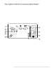
Troubleshooting the Analyzer To perform initial verification q Agilent 35670A Step 6. Check the following TTL clock signals using an oscilloscope and a 1 MΩ 10:1 probe. Signal Name Test Location Frequency Probable Faulty Assembly FREQ REF A7 TP1 19.923 MHz A7 CPU G20MHz A7 J3 pin 32C 19.
Agilent 35670A Troubleshooting the Analyzer To perform initial verification A7 Component Locator, Circuit Side 4-9
Troubleshooting the Analyzer To perform initial verification q Agilent 35670A Step 7. Check signals required for power up. • Using a logic probe, check the following signals.
Agilent 35670A Troubleshooting the Analyzer To troubleshoot the power supply To troubleshoot the power supply q Use this test to check the Power Supply and Fan assemblies. This test can also isolate the assembly causing the Power Supply to shut down. Step 1. Check the power supply LED. • Set the power switch to off ( O ). • Disconnect the ribbon cable from the A98 Power Supply assembly. • Set the power switch to on ( l ).
Troubleshooting the Analyzer To troubleshoot the power supply q Agilent 35670A Step 2. Determine if the Digital, Analog, or Input assemblies are causing the Power Supply assembly to shut down. • Set the power switch to off ( O ). • Pull the following assemblies out of the card nest about 1 inch: A6 Digital A5 Analog A2 Input (optional) A1/A2 Input • Set the power switch to on ( l ).
Agilent 35670A Troubleshooting the Analyzer To troubleshoot the power supply • Remove the A7 CPU assembly. See ‘’To remove CPU’’ on page 6-11. • Set the power switch to on ( l ). • If the power supply LED is still off, set the power switch to off ( O ), reconnect the CPU assembly, and go to Step 6. q Step 5. Repeat the following steps until the assembly causing the Power Supply assembly to shut down is located. • Set the power switch to off ( O ).
Troubleshooting the Analyzer To troubleshoot the power supply q Agilent 35670A Step 6. Determine if the Motherboard, Fan, or Rear Panel assembly is causing the Power Supply to shut down. • Disconnect the fan cable from A99 P90. • Set the power switch to on ( l ). • If the power supply LED is now on, the A90 Fan assembly is probably faulty. • Set the power switch to off ( O ). • Reconnect the fan cable. • Remove the rear panel and disconnect the cable from A10 P100.
Agilent 35670A Troubleshooting the Analyzer To troubleshoot power-up failures To troubleshoot power-up failures Use this test when the screen is defective, when the analyzer does not respond correctly to the keyboard, or when it takes more than 3 minutes for the keyboard to become active. Any of the following conditions may cause a power-up failure: q • A defective CPU or Memory assembly. • A defective assembly connected to the CPU assembly causing a bus failure.
Troubleshooting the Analyzer To troubleshoot power-up failures q Agilent 35670A Step 2. Determine if the power-on test passed or failed. • Set the power switch to off ( O ). • Set the power switch to on ( l ) while watching the power-on LEDs. The power-on LEDs are on the A7 CPU assembly and are visible through the rear panel. To see the LEDs easier, remove the seven screws holding the rear panel to the analyzer and lean the rear panel back. This also gives you access to reset switch SW2.
Agilent 35670A Troubleshooting the Analyzer To troubleshoot power-up failures Binary (DS5) (DS9) Hexadecimal ~Time LEDs Description Visible 1111 1111 0000 0000 FF 00 200 ms on 200 ms off A7 flashes LEDs 0000 1000 08 † starting A7 test 0000 0010 02 † A8 RAM DSACK test 0001 0100 14 † starting A8 RAM test 0001 0110 16 † starting A8 refresh test 0001 1100 1C 4s starting A8 program ROM test 0000 0000 00 4s clear LEDs 1010 0000 A0 † A7 MFP test 1010 0001 A1 † starting A7 DS
Troubleshooting the Analyzer To troubleshoot CPU, memory, and buses failures Agilent 35670A To troubleshoot CPU, memory, and buses failures q Use this test to isolate the failure when the power-on LEDs show a fail code or the analyzer locks up during the power-up tests. Step 1. Compare the LED fail code to the following table. • Set the power switch to off ( O ). • Set the power switch to on ( l ) while watching the power-on LEDs.
Agilent 35670A Troubleshooting the Analyzer To troubleshoot CPU, memory, and buses failures Binary (DS5) (DS9) Hexadecimal Probable Faulty Assembly 0000 0100 1111 1111 0001 0011 0000 0001 0001 0111 0001 1000 0000 1001 0000 1011 0001 1010 0001 1001 0000 1000 0001 0010 1010 0000 04 FF 13 01 17 18 09 0B 1A 19 08 12 A0 A7 CPU 0000 0010 0001 1011 0001 0100 0001 0110 0001 1100 02 1B 14 16 1C A8 Memory 0 = LED off 1 = LED on q Step 2. Determine if the CPU assembly is causing the failure.
Troubleshooting the Analyzer To troubleshoot CPU, memory, and buses failures Agilent 35670A • Disconnect the A7 CPU assembly from the Motherboard, Memory assembly, and cables. • Reconnect the CPU assembly to the Motherboard (do not connect the Memory assembly or cables to the CPU assembly). A7 Component Locator, Circuit Side • Set the power switch to on ( l ) while watching the power-on LEDs.
Agilent 35670A q Troubleshooting the Analyzer To troubleshoot CPU, memory, and buses failures Step 3. Determine if the Memory or Display assembly is causing the failure. • Set the power switch to off ( O ). • Reconnect the Memory assembly to the CPU assembly. • Set the power switch to on ( l ) while watching the power-on LEDs. The LEDs should sequence through 00 (clear LEDs) with 00 remaining on the LEDs. • Set the power switch to off ( O ). • Reconnect the display cable to A7 P2.
Troubleshooting the Analyzer To troubleshoot display failures Agilent 35670A To troubleshoot display failures q Caution Use this test to isolate display failures to the A101 Display assembly, A102 DC-DC Converter assembly, or A7 CPU assembly. Step 1. Check the DC-DC Converter assembly. • Set the power switch to off ( O ). • Connect the voltmeter to A102 TP1. • Set the power switch to on ( l ). • Check that the voltage reads is 210 10 Vdc.
Agilent 35670A q Troubleshooting the Analyzer To troubleshoot display failures Step 2. Check the CPU signals to the Display assembly. • Set the power switch to on ( l ). • Using a logic probe, check that the following TTL signals are toggling. • • • • • • Test Location Signal Name In/Out A7 P2(9) VSYNCEL A7 Out A7 P2(11) HSYNCELn A7 Out A7 P2(13) VCLK A7 Out A7 P2(15) VID A7 Out If the signals are incorrect, do the following: Set the power switch to off ( O ).
Troubleshooting the Analyzer To troubleshoot display failures q Agilent 35670A Step 3. Determine the probable faulty assembly by comparing the analyzer’s symptoms to the following table.
Agilent 35670A Troubleshooting the Analyzer To troubleshoot IIC bus failures To troubleshoot IIC bus failures Use this test to isolate IIC (Inter-IC) bus failures to one of the following assemblies: q • A7 CPU • A1/A2 Input • A5 Analog • A10 Rear Panel • A11 Keyboard Controller Step 1. Disconnect all assemblies connected to the CPU assembly’s IIC bus. • Set the power switch to off ( O ). • Remove the rear panel and disconnect the cable from A10 P100.
Troubleshooting the Analyzer To troubleshoot IIC bus failures q Agilent 35670A Step 2. Check the serial clock (SCL). • Attach a logic probe to A7 P7 pin 2 (SCL). • Set the power switch to on ( l ). • Press SW2 (reset switch) while monitoring A7 P7 pin 2 (SCL), the power-on LEDs, and the display. The TTL logic level should toggle when 00 is displayed and toggle continuously when Booting System is displayed.
Agilent 35670A Troubleshooting the Analyzer To troubleshoot IIC bus failures • If the signal does not toggle after SW2 is pressed, the A7 CPU assembly is probably faulty. • If no error messages are displayed after Booting System or A7 DS101 (green run LED) is off, go to page 4-29, ‘’To troubleshoot fast bus failures.’’ q Step 3. Check the serial data line (SDA). • Attach the logic probe to A7 P7 pin 1 (SDA). • Press SW2 while monitoring A7 P7 pin 1 (SDA), the power-on LEDs, and the display.
Troubleshooting the Analyzer To troubleshoot IIC bus failures q Agilent 35670A Step 4. Check the assemblies on the IIC bus by repeating the following steps for each assembly. • Set the power switch to off ( O ). • Reconnect one assembly at a time in the following order. A11 Keyboard Controller (cable to A7 P1) A10 Rear Panel (cable to A10 P100) A5 Analog A1/A2 Input (lower slot) A2 Input (upper slot) • Set the power switch to on ( l ).
Agilent 35670A Troubleshooting the Analyzer To troubleshoot fast bus failures To troubleshoot fast bus failures Use this test to isolate Fast Bus failures to the A7 CPU assembly or A6 Digital assembly. • Set the power switch to off ( O ). • Set the power switch to on ( l ) while holding in the [ System Utility ] key. The screen displays Fast Bus Diagnostic Test ... and the power-on LEDs are flashing. • If the analyzer did not respond correctly, the A7 CPU assembly is probably faulty.
Troubleshooting the Analyzer To troubleshoot fast bus failures 4-30 Agilent 35670A
Agilent 35670A Troubleshooting the Analyzer To perform self tests To perform self tests Use this test when one of the following occurs: q Caution • Performance test fails • Calibration fails • Trigger fails • GPIB fails • Microphone power fails • Serial port fails • Parallel port fails • Failure is intermittent Step 1. Run all the functional self tests. • Connect the rear panel SOURCE output to the rear panel TACH input using a BNC cable.
Troubleshooting the Analyzer To perform self tests q Agilent 35670A Step 2. Compare the analyzer’s self-test results to the following table. • When the tests have finished, press the following keys: [ Rtn ] [ TEST LOG ] • Press the [ PREVIOUS PAGE ] softkey until the first page of test log is displayed.
Agilent 35670A Troubleshooting the Analyzer To perform self tests Self-Test Troubleshooting Guide Failing Self Test Probable Faulty Assembly Adjustment Troubleshooting Test Interrupt A7 CPU Mult Fctn Peripheral A7 CPU Front Panel A11 Keyboard Controller GPIB A10 Rear Panel Disk Controller A7 CPU Disk FIFO A7 CPU IIC Bus (If only one assembly is failing) Assembly failing.
Troubleshooting the Analyzer To perform self tests Agilent 35670A Self-Test Troubleshooting Guide (continued) Failing Self Test Probable Faulty Assembly Source With LO fails and Source Without LO passes A6 Digital Source Without LO one channel A1/A2 Input A5 Analog Source Without LO channel 1 and 3 or channel 2 and 4 A2 Input Source With LO one channel A1/A2 Input A5 Analog Source With LO channel 1 and 3 or channel 2 and 4 A2 Input Input Offset one channel or channel 1 and 3 or channel 2 and 4
Agilent 35670A Troubleshooting the Analyzer To perform self tests Self-Test Troubleshooting Guide (continued) Failing Self Test Probable Faulty Assembly Adjustment Troubleshooting Test Input A-Wt Filter A1/A2 Input one channel or channel 1 and 3 or channel 2 and 4 Input A-Wt Filter all channels A6 Digital Input AAF/Bypass one channel or channel 1 and 3 or channel 2 and 4 A1/A2 Input Input AAF/Bypass all channels A6 Digital Input ICP Source † one channel or channel 1 and 3 or channel 2 and 4 A1/
Troubleshooting the Analyzer To perform self tests q Agilent 35670A Step 3. Determine the probable faulty assembly and next test by comparing the analyzer’s symptoms to the following table.
Agilent 35670A Troubleshooting the Analyzer To troubleshoot self-test lockup failures To troubleshoot self-test lockup failures q Use this test to continue troubleshooting if the analyzer locked up while running the functional test ALL. Step 1. Check the clock signal. • Set the power switch to on ( l ). • Using an oscilloscope and a 1 M 10:1 probe, check the following signal.
Troubleshooting the Analyzer To troubleshoot self-test lockup failures q Agilent 35670A Step 2. Run the IIC and fast bus self tests. • Press the following keys: [ System Utility ] [ CALIBRATN ] [ AUTO CAL OFF ] [ Input ] [ ALL CHANNELS ] [ CH* FIXED RANGE ] 1 [ Vpk ] [ System Utility ] [ MORE ] [ SELF TEST ] [ TEST LOG ] [ Rtn ] [ FUNCTIONL TESTS ] [ I/O ] [ IIC BUS ] • If the keyboard is not active, or the analyzer locks up when a key is pressed, go to page 4-25, ‘’To troubleshoot IIC bus failures.
Agilent 35670A q Caution Troubleshooting the Analyzer To troubleshoot self-test lockup failures Step 4. Run the remaining self tests. • Connect the rear panel SOURCE output to the rear panel TACH input using a BNC cable. • Remove all cables from the front panel input connectors. The ICP self test outputs approximately 30 Vdc on the input connectors. Before starting the self tests, disconnect all devices connected to the input connectors. Devices left connected during the ICP self test may be damaged.
Troubleshooting the Analyzer To troubleshoot intermittent failures Agilent 35670A To troubleshoot intermittent failures Use this test to isolate intermittent failures to the assembly. • Determine if your intermittent failure is caused by one of the following common causes. Common Reasons Troubleshooting Procedure Loose screws and cables Check that the screws in the analyzer are tight and that the cables are firmly in their sockets.
Agilent 35670A Troubleshooting the Analyzer To troubleshoot intermittent failures • Press the following keys: [ Preset ] [ DO PRESET ] [ System Utility ] [ CALIBRATN ] [ AUTO CAL OFF ] [ Input ] [ ALL CHANNELS ] [ CH* FIXED RANGE ] 1 [ Vpk ] [ System Utility ] [ MORE ] [ SELF TEST ] [ TEST LOG ] [ CLEAR TEST LOG ] [ Rtn ] [ LOOP MODE ON ] [ FUNCTIONL TESTS ] [ ALL ] [ C ONTINUE ] • After this test detects a failure, press the following keys: [ Rtn ] [ LOOP MODE OFF ] • Compare the analyzer’s test log to
Troubleshooting the Analyzer To troubleshoot performance test failures Agilent 35670A To troubleshoot performance test failures q With the exception of the Quick Confidence test, all functional self tests must pass before the following table is valid. Step 1. If the analyzer failed a performance test, compare the failing performance test to the following table. If more than one performance test is failing, use the entry that is closest to the beginning of the table.
Agilent 35670A Troubleshooting the Analyzer To troubleshoot performance test failures Failing Performance Test Probable Faulty Assembly (in order of probabilty) Adjustment Troubleshooting Test Amplitude linearity one channel A1/A2 Input A5 Analog Input dc offset, page 5-10 ADC gain, offset, and reference, page 5-7 Input and ADC, page 4-51 Four channel, page 4-54 Amplitude linearity channel 1 and 3 or channel 2 and 4 A2 Input Input dc offset, page 5-10 Amplitude linearity all channels A5 Analog
Troubleshooting the Analyzer To troubleshoot performance test failures Agilent 35670A Failing Performance Test Troubleshooting Guide Failing Performance Test Probable Faulty Assembly (in order of probabilty) Spurious signals one channel A1/A2 Input A5 Analog Spurious signals channel 1 and 3 or channel 2 and 4 A2 Input Spurious signals all channels A5 Analog mechanical A6 Digital Noise one channel A1/A2 Input A5 Analog Noise channel 1 and 3 or channel 2 and 4 A2 Input Noise all channels A5 Ana
Agilent 35670A Troubleshooting the Analyzer To troubleshoot source and calibrator failures To troubleshoot source and calibrator failures q Use this test to isolate source and calibrator failures to the A6 Digital assembly, the A5 Analog assembly, the A1/A2 Input assembly, the A12 BNC assembly, or the A10 Rear Panel assembly. Step 1. Check the sine wave output. • Set the power switch to on ( l ). • Connect an oscilloscope to the analyzer’s SOURCE connector using a BNC cable.
Troubleshooting the Analyzer To troubleshoot source and calibrator failures q Agilent 35670A Step 2. Check the dc offset. • Connect the voltmeter to A5 TP3. • Press the following keys: [ LEVEL ] 0 [ Vpk ] [ DC OFFSET ] • Rotate the RPG knob while monitoring the voltmeter. • If the voltmeter’s voltage does not change from +2.3 to 2.3 as the dc offset value is varied between 10 and +10 Vdc, the A5 Analog assembly is probably faulty.
Agilent 35670A q Troubleshooting the Analyzer To troubleshoot source and calibrator failures Step 3. Check the periodic chirp output. • Press the following keys: [ DC OFFSET ] 0 [V] [ LEVEL ] 1 [ Vpk ] [ PERIODIC CHIRP ] • Using an an oscilloscope and a 1:1 probe, check the following signal.
Troubleshooting the Analyzer To troubleshoot source and calibrator failures q Agilent 35670A Step 4. Check the calibrator output. • Set the power switch to off ( O ). • Remove the A1/A2 Input assembly and attach a test clip patch cord to TP 17. Connect a 10:1 oscilloscope probe to the patch cord and TP 8 (ground). • Reinstall the Input assembly in the card nest with patch cord and probe attacted. • Set the power switch to on ( l ).
Agilent 35670A Troubleshooting the Analyzer To troubleshoot source and calibrator failures • Press the following keys: [ System Utility ] [ CALIBRATN ] [ AUTO CAL OFF ] [ Input ] [ ALL CHANNELS ] [ CH* FIXED RANGE ] 1 [ Vpk ] [ Source ] [ SOURCE ON ] [ LEVEL ] 1 [ Vpk ] [ System Utility ] [ MORE ] [ SERVICE TESTS ] [ SPCL TEST MODES ] [ HIGH LEVEL CAL ] • If the signal does not look like the following figure, the A5 Analog assembly is probably faulty.
Troubleshooting the Analyzer To troubleshoot source and calibrator failures Agilent 35670A ❑ Step 5. Check the Input assembly. • Using an oscilloscope and a 10:1 probe, check the following signal.
Agilent 35670A Troubleshooting the Analyzer To troubleshoot input and ADC failures To troubleshoot input and ADC failures q Use this test to isolate input failures in two channel analyzers to the A1 Input assembly, A5 Analog assembly, or A12 BNC assembly. Step 1. Check the input path.
Troubleshooting the Analyzer To troubleshoot input and ADC failures Agilent 35670A This is only a quick check of the Input assembly. If the Input assembly’s amplitude is still suspected of failing, set the analyzer to the failing range, impedance, and frequency. Connect a signal equal to the range setting to the failing channel. When the input level equals the range level, A1 P200 (channel 1) or A1 P700 (channel 2) should be 2.83 ±0.28 Vp-p.
Agilent 35670A q Troubleshooting the Analyzer To troubleshoot input and ADC failures Step 2. Check the dc offset DAC. • Using the BNC-to-SMB cable, connect the oscilloscope to A1 P200 to check channel 1 or to A1 P700 to check channel 2. If you changed the input signal or range, set the input signal to 2 Vp-p and the range to 1 Vpk. • Set the oscilloscope to 700 mV/div.
Troubleshooting the Analyzer To troubleshoot input failures on four channel analyzers Agilent 35670A To troubleshoot input failures on four channel analyzers q Use this test to isolate the failure when one channel fails in a four channel analyzer. Step 1. Run the input and quick confidence self tests. • Set the power switch to on ( l ).
Agilent 35670A q Troubleshooting the Analyzer To troubleshoot input failures on four channel analyzers Step 2. Exchange the Input assemblies. • Set the power switch to off ( O ). • Exchange the Input assembly in the lower slot with the Input assembly in the upper slot. • Reconnect the cables to the A5 Analog assembly. • Set the power switch to on ( l ).
Troubleshooting the Analyzer To troubleshoot distortion failures Agilent 35670A To troubleshoot distortion failures q Use this test to isolate distortion failures to the A1/A2 Input assembly, the A5 Analog assembly, or to mechanical failures. Step 1. Check mechanical ground connections. • Check that the Digital assembly, Input assembly, and Analog assembly are completely in the card nest and making good contact with the grounding guides at the sides of the card nest.
Agilent 35670A Troubleshooting the Analyzer To troubleshoot disk drive failures To troubleshoot disk drive failures q This test isolates disk drive failures to the A7 CPU, the A100 Disk Drive assembly, or the flexible disk. Step 1. Check the disk controller on the A7 CPU assembly.
Troubleshooting the Analyzer To troubleshoot disk drive failures q Agilent 35670A Step 3. Check that the Disk Drive assembly can read and write to all sectors of a flexible disk. The read/write self test can take up to 40 minutes to complete if there are no failures. • Press the [ READ/WRITE ALL ] softkey. • If the self test aborts and displays the message Bad or unformatted media, insert a new formatted disk and repeat the previous step.
Agilent 35670A Troubleshooting the Analyzer To troubleshoot auto-range failures To troubleshoot auto-range failures Use this test to check the auto-range and overload detector circuits on the A1/A2 Input assembly. This test assumes that calibration and all self tests passed. • Set the power switch to on ( l ).
Troubleshooting the Analyzer To troubleshoot auto-range failures Agilent 35670A • Press the following keys: [ CHANNEL 1 ] [ CHANNEL 1 RANGE ] The range should be set to 5 dBVrms. • Press [ Rtn ]. • Repeat steps 5 and 6 for each channel. • If only one channel, or channel 1 and 3, or channel 2 and 4 are failing, the A1/A2 Input assembly is probably faulty. In the two channel analyzer, the A1 Input assembly provides the circuits for channel 1 and 2.
Agilent 35670A Troubleshooting the Analyzer To troubleshoot DIN connector failures To troubleshoot DIN connector failures Use this test to determine if the fuse for the DIN connector is failing before replacing the A10 Rear Panel assembly. • Set the power switch to on ( l ). • Check the voltage on pin 2 of the DIN connector for +5V. • If the voltage is correct, the A10 Rear Panel assembly is probably faulty. • If the voltage is incorrect, replace A10 F200.
Troubleshooting the Analyzer To troubleshoot trigger failures Agilent 35670A To troubleshoot trigger failures q Use this test when the trigger mode is suspected of failing or the Input Trigger self test fails on all channels. Step 1. Check trigger modes. • Set the power switch to on ( l ).
Agilent 35670A Troubleshooting the Analyzer To troubleshoot trigger failures • Connect the frequency synthesizer to the analyzer’s rear panel EXT TRIG connector using a BNC cable. • Press the following keys allowing enough time for the analyzer to trigger before pressing the next key.
Troubleshooting the Analyzer To troubleshoot trigger failures q q Agilent 35670A Step 2. Determine the probable faulty assembly or next step by comparing the trigger failure to the following table. If the trigger failure matches more than one entry in the table, use the entry closest to the beginning of the table.
Agilent 35670A Troubleshooting the Analyzer To troubleshoot trigger failures • If the signal at A5 TP 204 is toggling, the A6 Digital assembly is probably faulty. • If the signal at A5 TP 204 is not toggling, the A5 Analog assembly is probably faulty.
Troubleshooting the Analyzer To troubleshoot trigger failures q Agilent 35670A Step 4. Check external trigger signal to the Analog assembly. • Set the power switch to off ( O ). • Remove the seven screws holding the rear panel to the analyzer and lean the rear panel back until the A10 Rear Panel assembly is visible. Keep the cables connected. • Set the power switch to on ( l ). • Change the frequency synthesizer’s amplitude to 2 Vp-p.
Agilent 35670A Troubleshooting the Analyzer To troubleshoot memory battery failures To troubleshoot memory battery failures Use this test when battery-backed-up memory is suspected of failing. This test separates Memory assembly failures from memory battery failures. • Press the following keys: [ Preset ] [ DO PRESET ] [ System Utility ] [ CLOCK SETUP ] [ DATE MMDDYY ] 010101 [ ENTER ] • Set the power switch to off ( O ), then to on ( l ).
Troubleshooting the Analyzer To troubleshoot memory battery failures 4-68 Agilent 35670A
Agilent 35670A Troubleshooting the Analyzer To troubleshoot microphone power and adapter failures To troubleshoot microphone power and adapter failures q Use this test to isolate Microphone failures to the A5 Analog assembly or option UK4, Microphone Adapter and Power Supply. Step 1. Check mic pwr on the analyzer’s front panel. • Set the power switch to on ( l ). • Check the voltage on pin 2 of the mic pwr connector for +8 ±0.5 Vdc.
Troubleshooting the Analyzer To troubleshoot tachometer failures Agilent 35670A To troubleshoot tachometer failures q Use this test to isolate tachometer failures to the A10 Rear Panel assembly or A6 Digital assembly. Step 1. Check the rear panel tachometer input. • Set the power switch to off ( O ). • Remove the seven screws holding the rear panel to the analyzer and lean the rear panel back until the A10 Rear panel assembly is visible. Keep the cables connected.
Agilent 35670A q Troubleshooting the Analyzer To troubleshoot tachometer failures Step 2. Check the tachometer range function. • Set the oscilloscope for 20 s/div. • Press the following keys: [ Rtn ] [ LOOP MODE OFF ] [ Rtn ] [ SERVICE TESTS ] [ SPCL TEST MODES ] [ SOURCE LEVEL ] [ Source ] [ SOURCE ON ] [ LEVEL ] 500 [ mVpk ] [ Trigger ] [ TACHOMETR SETUP ] [ TRG RANGE +/− 20 ] • Check that the oscilloscope displays a dc voltage of approximately 4 Vdc. • Press [ TRG RANGE +/ 4 ].
5 Adjusting the Analyzer 5-1
Adjusting the Analyzer This chapter contains the adjustment procedures for the Agilent 35670A Dynamic Signal Analyzer. Use these adjustments if the analyzer does not meet its specifications or if instructed in chapter 4, ‘’Troubleshooting the Analyzer,’’ or chapter 6, ‘’Replacing Assemblies,’’ to perform these adjustments. These adjustments are not required for routine maintenance. Allow the Agilent 35670A analyzer to warm up for an hour before doing any of the adjustments.
Agilent 35670A Adjusting the Analyzer Safety Considerations Although the Agilent 35670A analyzer is designed in accordance with international safety standards, this guide contains information, cautions, and warnings that must be followed to ensure safe operation and to keep the unit in safe condition. Adjustments in this chapter are performed with power applied and protective covers removed.
Adjusting the Analyzer Agilent 35670A Remote Operation Adjustments can be set up using the remote operation capability of the Agilent 35670A analyzer. The following table lists the adjustments and corresponding GPIB codes. See the Agilent 35670A GPIB Programmer’s Guide for general information on remote operation.
Agilent 35670A Adjusting the Analyzer To adjust the frequency reference To adjust the frequency reference This procedure adjusts the 19.923 MHz (or, to be exact, 19.922944 MHz) frequency reference circuit on the A7 CPU assembly. This circuit is the source of the timing reference for the A1/A2 Input and A5 Analog assemblies. Equipment Required: Frequency Counter 10:1 Oscilloscope Probe • Set the power switch to off ( O ).
Adjusting the Analyzer To adjust the source Agilent 35670A To adjust the source This procedure adjusts the source dc offset on the A5 Analog assembly. Equipment Required: Multimeter BNC-to-Dual Banana Cable • Connect the multimeter to the analyzer’s rear-panel SOURCE connector. • Press the following keys: [ System Utility ] [ MORE ] [ SERVICE TESTS ] [ ADJUSTMTS ] [ SOURCE ADJUSTMNT ] [ DC OFFSET ] • Adjust A5 R48 for 0 Vdc±1 mV. • Press the [ FILTER DC OFFSET ] softkey. • Adjust A5 R59 for 0 Vdc ±1 mV.
Agilent 35670A Adjusting the Analyzer To adjust the ADC gain, offset and reference To adjust the ADC gain, offset and reference This procedure adjusts the second-pass gain, the first-pass offset, and the reference voltage for the ADC on the A5 Analog assembly. This prevents nonlinear Analog-to-Digital Converter (ADC) operation near the Digital-to-Analog Converter (DAC) transition levels.
Adjusting the Analyzer To adjust the ADC gain, offset and reference Agilent 35670A • Set the oscilloscope as follows: Channel 1 Volts/Div Offset Coupling 20 mV/div 0V 1 MΩ ac Channel 2 Volts/Div Offset Coupling 500 mV/div 0V 1 MΩ ac Time Base Time/Div Sweep 1.0 ms/div Triggered Trigger Source Level Slope Mode Channel 2 500 mV Positive Edge Display Mode Averaging No. of Avg. Screen Repetitive On 8 Single • Remove the cable from A5 P4. Connect a jumper from A5 TP8 to A5 TP300.
Agilent 35670A Adjusting the Analyzer To adjust the ADC gain, offset and reference • Press the following keys: [ System Utility ] [ MORE ] [ SERVICE TESTS ] [ ADJUSTMTS ] [ ADC ADJUSTMNT ] [ OFFSET ] Wait for the analyzer to set up the adjustment. The analyzer is ready when the adjustment message appears on the screen. • If the oscilloscope display looks like the following figure, go to step 17.
Adjusting the Analyzer To adjust the input dc offset Agilent 35670A To adjust the input dc offset This procedure minimizes the residual dc response of the A1/A2 Input assemblies. The standard two channel analyzer has one A1 Input assembly. The optional four channel analyzer has two A2 Input assemblies: channel 1 and 3 are routed to the A2 Input assembly in the lower slot and channel 2 and 4 are routed to the A2 Input assembly in the upper slot.
Agilent 35670A q Adjusting the Analyzer To adjust the input dc offset For the standard two channel analyzer, do the following to adjust input dc offset: • Set the power switch to on ( I ). • Press the following keys: [ System Utility ] [ MORE ] [ SERVICE TESTS ] [ ADJUSTMTS ] [ CHANNEL 1 ADJUSTMNT ] [ OFFSET ] Wait for the analyzer to set up the adjustment. The analyzer is ready when the adjustment message appears on the screen. • Adjust A1 R39 for a Y: reading of 90 dBVrms or less.
Adjusting the Analyzer To adjust the input dc offset q Agilent 35670A For the optional four channel analyzer, do the following to adjust input dc offset: • Set the power switch to on ( I ). • Press the following keys: [ System Utility ] [ MORE ] [ SERVICE TESTS ] [ ADJUSTMTS ] [ CHANNEL 1 ADJUSTMNT ] [ OFFSET ] Wait for the analyzer to set up the adjustment. The analyzer is ready when the adjustment message appears on the screen. • Adjust A2 R39 in the lower slot for a Y: reading of 90 dBVrms or less.
Agilent 35670A Adjusting the Analyzer To adjust common mode rejection To adjust common mode rejection This procedure optimizes the common mode rejection of the A1/A2 Input assemblies. The standard two channel analyzer has one A1 Input assembly. The optional four channel analyzer has two A2 Input assemblies: channel 1 and 3 are routed to the A2 Input assembly in the lower slot and channel 2 and 4 are routed to the A2 Input assembly in the upper slot.
Adjusting the Analyzer To adjust common mode rejection q Agilent 35670A For the standard two channel analyzer, do the following to adjust common mode rejection: • Set the power switch to off ( O ). • Connect the BNC(f)-to-minigrabber adapter to the BNC cable. Connect both minigrabber clips (signal and ground) to A5 TP8 and the BNC connector to the analyzer’s CH 1 connector. • Set the power switch to on ( I ).
Agilent 35670A q Adjusting the Analyzer To adjust common mode rejection For the optional four channel analyzer, do the following to adjust common mode rejection: • Set the power switch to off ( O ). • Connect the BNC(f)-to-minigrabber adapter to the BNC cable. Connect both minigrabber clips (signal and ground) to A5 TP8 and the BNC connector to the analyzer’s CH 1 connector. • Set the power switch to on ( I ).
Adjusting the Analyzer To adjust common mode rejection Agilent 35670A • While monitoring the Y: value, adjust A2 R543 in the lower slot for a minimum marker value. • Disconnect the BNC cable from the analyzer’s CH 3 connector and connect to the CH 4 connector. • Press the the following keys: [ Rtn ] [ CHANNEL 4 ADJUSTMNT ] [ CMRR ] Wait for the analyzer to set up the adjustment. The analyzer is ready when the adjustment message appears on the screen.
Agilent 35670A Adjusting the Analyzer To adjust filter flatness To adjust filter flatness This procedure adjusts the anti-alias filter on the A1/A2 Input assemblies. The standard two channel analyzer has one A1 Input assembly. The optional four channel analyzer has two A2 Input assemblies: channel 1 and 3 are routed to the A2 Input assembly in the lower slot and channel 2 and 4 are routed to the A2 Input assembly in the upper slot.
Adjusting the Analyzer To adjust filter flatness q Agilent 35670A For the standard two channel analyzer, do the following to adjust filter flatness: • Set the power switch to on ( I ). • Press the following keys: [ System Utility ] [ MORE ] [ SERVICE TESTS ] [ ADJUSTMTS ] [ CHANNEL 1 ADJUSTMNT ] [ 50 kHz ] Wait for the analyzer to set up the adjustment. The analyzer is ready when the adjustment message appears on the screen. • While monitoring the Yr: value, adjust A1 R115 for a marker value of 0 0.1 dB.
Agilent 35670A q Adjusting the Analyzer To adjust filter flatness For the optional four channel analyzer, do the following to adjust filter flatness: • Set the power switch to on ( I ). • Press the following keys: [ System Utility ] [ MORE ] [ SERVICE TESTS ] [ ADJUSTMTS ] [ CHANNEL 1 ADJUSTMNT ] [ 25 kHz ] Wait for the analyzer to set up the adjustment. The analyzer is ready when the adjustment message appears on the screen.
Adjusting the Analyzer To adjust filter flatness Agilent 35670A • Press the following keys: [ Rtn ] [ CHANNEL 3 ADJUSTMNT ] [ 25 kHz FLATNESS ] Wait for the analyzer to set up the adjustment. The analyzer is ready when the adjustment message appears on the screen. • While monitoring the Yr: value, adjust A2 R615 in the lower slot for a marker value of 0 0.1 dB. • Press the following keys: [ Rtn ] [ CHANNEL 4 ADJUSTMNT ] [ 25 kHz FLATNESS ] Wait for the analyzer to set up the adjustment.
Agilent 35670A Adjusting the Analyzer To adjust the display voltage To adjust the display voltage This procedure adjusts the A102 DC-DC Converter assembly’s display voltage to match the voltage required by the A101 Display assembly. This adjustment is only required when the DC-DC Converter assembly or the Display assembly is replaced. Equipment Required: Multimeter Warning The display voltage is +210 Vdc 10 Vdc nominal. Use caution when performing this adjustment to avoid personal injury.
Adjusting the Analyzer To adjust the display voltage 5-22 Agilent 35670A
6 Replacing Assemblies 6-1
Replacing Assemblies This chapter tells you what to do before and after you replace an assembly and shows you how to disassemble the analyzer. Warning Disconnect the power cord from the rear panel before disassembly or assembly of the Agilent 35670A. Even with power removed, there can be sufficient stored energy in some circuits to cause personal injury. These voltages will discharge to a relatively safe level approximately five seconds after the power cord is disconnected.
Agilent 35670A Replacing Assemblies What to do before replacing the CPU assembly What to do before replacing the CPU assembly The analyzer’s serial number and firmware options are stored in EEPROM (U27) on the A7 CPU assembly. Before replacing the CPU assembly, remove A7 U27 from the faulty assembly and insert into the new assembly. Caution All firmware options will be lost if A7 U27 is not removed from the faulty assembly and inserted into the new assembly.
Replacing Assemblies What to do after replacing an assembly Agilent 35670A What to do after replacing an assembly • • • • Reinstall all assemblies and cables that were removed during troubleshooting. Do the required adjustments listed in the following table. Do the self test, page 4-31. Do the required performance tests listed in the following table.
Agilent 35670A Replacing Assemblies What to do after replacing an assembly Assembly Replaced Required Adjustment Required Performance Test A7 CPU Frequency reference, page 5-5 Frequency accuracy A8 Memory A9 NVRAM A10 Rear Panel Tach function (option 1D0 only) External trigger A11 Keyboard Controller A12 BNC A13 Primary Keypad A14 Secondary Keypad A22 BNC A90 Fan A98 Power Supply A99 Motherboard A100 Disk Drive A101 Display Display voltage, page 5-21 A102 DC-DC Converter Display voltage, page 5
Replacing Assemblies To remove cover Agilent 35670A To remove cover 14 mmPlace the analyzer on its front panel. Using a 2 hex driver, loosen the four corner screws. 6-6 Slide the cover straight up.
Agilent 35670A Replacing Assemblies To remove rear panel To remove rear panel 1 Remove cover (see ‘’To remove cover’’). 2screwsUsing a T-15 torx driver, remove the seven from the rear panel. Pull the rear panel straight off. 3cableDisconnect the ribbon cable and the coaxial from the A10 Rear Panel assembly.
Replacing Assemblies To remove front panel Agilent 35670A To remove front panel 1 Remove cover (see ‘’To remove cover’’). 3disconnect Slide A5 Analog assembly part way out and gray mic cable. 6-8 2 Remove assembly retainer bracket. 4screwsUsing a T-15 torx driver, remove the two on each side of the front panel.
Agilent 35670A 5 Pull the top of the front panel out of the frame. Replacing Assemblies To remove front panel 6panel.Disconnect the ribbon cables from the front Disconnect the coaxial cables connected to the A12/A22 BNC assembly.
Replacing Assemblies To remove disk drive Agilent 35670A To remove disk drive 1 Remove cover (see ‘’To remove cover’’). 2 Disconnect the disk drive cable. 3screwsUsing a T-10 torx driver, loosen the three at the back of the disk drive bracket. 4 Slide the disk drive back and lift up.
Agilent 35670A Replacing Assemblies To remove CPU To remove CPU 1 Remove cover (see ‘’To remove cover’’). 2screwsUsing a T-10 torx driver, remove the nine from the A7 CPU assembly. Lift the assembly up, unpluging the A7 CPU assembly from the A8 Memory assembly and A99 Motherboard. 3CPU Disconnect the ribbon cables from the A7 assembly. 4optionsTheareanalyzer’s serial number and firmware stored in EEPROM (U27) on the A7 CPU assembly.
Replacing Assemblies To remove NVRAM Agilent 35670A To remove NVRAM 1CPU’’). Remove A7 CPU assembly (see ‘’To remove 2screwsUsing a T-10 torx driver, remove the four from the A9 NVRAM assembly.
Agilent 35670A Replacing Assemblies To remove memory To remove memory 1CPU’’). Remove A7 CPU assembly (see ‘’To remove 2screwsUsing a T-10 torx driver, remove the eight Remove optional A9 NVRAM assembly from the A8 Memory assembly. (see ‘’To remove NVRAM’’).
Replacing Assemblies To remove power supply Agilent 35670A To remove power supply 1panel’’). Remove rear panel (see ‘’To remove rear 2PowerDisconnect the ribbon cable from the A98 Supply assembly. 3screwsUsing a T-15 torx driver, remove the six from the A98 Power Supply assembly. 4off ( OSet) position the front panel power switch in the (switch in the out position).
Agilent 35670A 5powerUsing a straight-edge screw driver, hold the 6up. switch rod in position and lift the A98 Power Replacing Assemblies To remove power supply Lift the A98 Power Supply assembly straight Supply to disengage it from the power switch rod.
Replacing Assemblies To remove motherboard Agilent 35670A To remove motherboard 1‘’To remove Remove A98 Power Supply assembly (see power supply’’). Remove A7 CPU 2Motherboard. Disconnect the fan cable from the A99 3 4Motherboard. Unplug all assemblies from the A99 ) assembly (see ‘’To remove CPU’’). Remove assembly retainer bracket.
Agilent 35670A Replacing Assemblies To remove motherboard 5two screws Using a 5 mm open-ended wrench, remove the 6screwsUsing T-10 torx driver, remove the twelve from the EXT MONITOR connector. in A99 Motherboard.
Replacing Assemblies To remove dc-dc converter Agilent 35670A To remove dc-dc converter 1panel’’). Remove front panel (see ‘’To remove front Remove A7 CPU assembly (see ‘’To 2screwsUsing a T-10 torx driver, remove the five from the front wall. 3 Using a T-10 torx driver, remove the four screws from the shield. Unplug ribbon cables. 4screwsUsing a T-10 torx driver, remove the four from the A102 DC-DC Converter assembly. remove CPU’’).
7 Replaceable Parts 7-1
Replaceable Parts This chapter contains information for ordering replacement parts for the Agilent 35670A Dynamic Signal Analyzer.
Agilent 35670A Replaceable Parts Ordering Information Direct Mail Order System Within the U.S.A., Agilent Technologies can supply parts through a direct mail order system. Advantages of the Direct Mail Order System are: • Direct ordering and shipment from the Agilent Parts Center. • No maximum or minimum on any mail order. There is a minimum order for parts ordered through a local Agilent sales and service office when the orders require billing and invoicing. • Transportation charges are prepaid.
Replaceable Parts Assemblies Agilent 35670A Assemblies After replacing an assembly, see ‘’What to do after replacing an assembly’’ in chapter 6 for required adjustments and performance tests. The reference designator for the screws that fasten the A90 Fan assembly is MP600. The reference designator for the screws that fasten the A98 Power Supply assembly is MP603. The reference designator for the screws that fasten all other assemblies is MP601.
Agilent 35670A Ref Des Replaceable Parts Assemblies Agilent Part CD Qty Number Description Mfr Code Mfr Part Number A1 A2 A5 A6 A7 35670-69501 35670-69502 35670-69505 35670-69506 35670-69507 9 0 3 4 5 1 2 1 1 1 INPUT ASSEMBLY - 2 CHANNEL INPUT ASSEMBLY - 4 CHANNEL ANALOG ASSEMBLY DIGITAL ASSEMBLY CPU ASSEMBLY † 28480 28480 28480 28480 28480 35670-69501 35670-69502 35670-69505 35670-69506 35670-69507 A8 A9 A10 A11 A12 35670-66508 35670-66509 35670-66510 35670-66511 35670-66512 6 7 4 5 6 1 1
Replaceable Parts Cables Agilent 35670A Cables Ref Des Agilent Part CD Qty Number Description Mfr Code Mfr Part Number W1 W2 W3 W4 W5 03585-61603 03585-61604 03586-61678 35665-61601 8120-6243 5 6 5 7 9 2 3 2 1 1 CBL-ASM CXL FSMB/FSMB 100MM OR CBL-ASM CXL FSMB/FSMB 177MM YL CBL-ASM CXL FSMB/FSMB 205MM GY CBL-ASM CDIN/FHSG 80MM MULT CBL-POWER 60POS RIBBON 75MM LG 28480 28480 28480 28480 28480 03585-61603 03585-61604 03586-61678 35665-61601 8120-6243 W6 W7 W8 W9 W10 8120-6236 8120-6242 8120-624
Agilent 35670A Replaceable Parts Instrument Covers and Handles Instrument Covers and Handles Ref Des Agilent Part CD Qty Number Description Mfr Code Mfr Part Number MP1 MP2 MP4 MP10 MP12 35670-64101 5021-5483 5062-4806 35670-64102 1540-0292 5 4 9 6 9 1 2 1 1 1 SHTF ASSY-COVER ALV COVER LATCHES MOLD BUMPER SET 4PC FF CORNRS IMPACT COVER - 35670A PKG-CASE ACCESSORY 28480 28480 28480 28480 00955 35670-64101 5021-5483 5062-4806 35670-64102 1051-B-2 MP13 MP15 1530-0272 8160-0689 4 9 1 2 VIEWIN
Replaceable Parts Assembly Covers and Brackets Agilent 35670A Assembly Covers and Brackets Ref Des Agilent Part CD Qty Number Description Mfr Code Mfr Part Number MP100 MP101 MP102 MP103 MP104 35670-00605 35670-01203 35670-01204 35670-01205 35670-04102 0 6 7 8 0 1 1 1 1 1 SHTF SHIELD DISP PWR SUPPLY SHTF BRKT,PCB RETAINER SHTF BRACKET-FAN AL SHTF DISC BRKT SHTF SLOT PLUG 28480 28480 28480 28480 28480 35670-00605 35670-01203 35670-01204 35670-01205 35670-04102 MP105 MP106 35670-44701 4040-232
Agilent 35670A Replaceable Parts Front Panel Parts Front Panel Parts The reference designator for the screws that fasten the bezel (MP208) to the front frame (MP201) is MP604. The reference designator for the nuts that fasten the A101 Display assembly to the front frame is MP611. The reference designator for the screws that fasten the front frame to the chassis is MP603.
Replaceable Parts Rear Panel Parts Agilent 35670A Rear Panel Parts The reference designator for the screws that fasten the KEYBOARD connector and A10 Rear Panel assembly to the rear panel is MP601. The reference designator for the screws that fasten the rear panel to the chassis is MP603. Caution The POWER SELECT switch must be in the DC position (out position) when the key cap (MP315) is removed. If the switch is not in the DC position when the key cap is removed, the switch may be damaged.
Agilent 35670A Replaceable Parts Chassis Parts Chassis Parts Ref Des Agilent Part CD Qty Number Description Mfr Code Mfr Part Number MP400 MP401 MP402 MP403 MP404 35670-00101 35670-00102 35670-04103 35650-00601 35670-64302 1 2 1 2 8 1 1 2 1 1 SHTF-CHASSIS ASSY SHTF WALL ASSY FRONT INPUT BD INSULATOR SHTF CVR-SHLD MUFL LBL CABLE 2CH CBL ROUTINE 28480 28480 28480 28480 28480 35670-00101 35670-00102 35670-04103 35650-00601 35670-64302 MP405 35670-64304 0 2 LBL CABLE 4CH CBL ROUTINE 28480 3
Replaceable Parts Screws, Washers, and Nuts Agilent 35670A Screws, Washers, and Nuts Ref Des Agilent Part CD Qty Number MP600 0515-0374 4 16 MP601 0515-0430 3 66 MP602 MP603 MP604 0515-1940 0515-2043 0515-1622 2 8 7 MP607 MP608 MP611 MP613 MP619 2190-0099 2950-0035 0535-0031 2190-0060 1252-0699 2 8 2 7 9 Description 4 21 4 SCREW-MACHINE ASSEMPLY M3 X 0.5 10MM-LG SCREW-MACHINE ASSEMPLY M3 X 0.5 6MM-LG SCR-MCH M2.5 6MMLG PHTX SST * SCR-MCH M4.0 8MMLG FHTX SST * SCR-CAP M4.
Agilent 35670A Replaceable Parts Option UK4 Parts Option UK4 Parts 7-13
Replaceable Parts Option UK4 Parts Ref Des Agilent 35670A Agilent Part CD Qty Number Description Mfr Code Mfr Part Number A77 A77P2 35670-66577 1252-5280 3 4 1 4 MICROPHONE PC ASSEMBLY CONN-LEMO 7-CNT FEMALE RT - PC 28480 00268 A77P10 A77SW 1 MP801 1252-1481 3101-3124 9 4 1 4 CON-RECT D-SUB 15CKT 15PN THL SW -SL .02A 20VA1D 00779 09353 35670-00121 5 1 SHTF-BTTM OUTBOX W/SILKSCREEN 28480 35670-66577 EPG.1B.307.
8 Circuit Descriptions 8-1
Circuit Descriptions This chapter contains the overall instrument description and individual assembly descriptions for the Agilent 35670A Dynamic Signal Analyzer. The overall instrument description lists the assemblies in the analyzer and describes the analyzer’s overall block diagrams. The assembly descriptions give additional information for each assembly. For signal connections and descriptions, see chapter 9, ‘’Voltages and Signals.
Agilent 35670A Circuit Descriptions Overall Instrument Description Overall Block Diagram BNC The following figures show the overall block diagrams for both the two channel and the four channel analyzer. Each block in the diagrams represents a functional block in the analyzer. The assembly that performs the function is listed in the block. Contains the BNC connectors for both input channels and the source.
Circuit Descriptions Overall Instrument Description Agilent 35670A Secondary Keypad Consists of hardkeys and softkeys. Power Supply Supplies the dc voltages shown in the block diagram. See “Power Supply Voltage Distribution” in chapter 9 for additional information. Rear Panel Provides the interface for devices connected to its GPIB connector, parallel connector, serial connector, and DIN keyboard connector.
Agilent 35670A Circuit Descriptions Overall Instrument Description Four Channel Overall Block Diagram 8-5
Circuit Descriptions A1 Input Agilent 35670A A1 Input ICP Source The A1 Input assembly is the input assembly for the two channel analyzer. The A1 Input assembly conditions the channel 1 and channel 2 input signals before they are sent to the analog-to-digital converter on the A5 Analog assembly. The A1 Input assembly sets the voltage ranges, conditions the input signals, and filters out alias components.
Agilent 35670A DC Offset DAC Circuit Descriptions A1 Input Compensates for any dc offset added to the input signal due to circuitry in the signal path. The required dc offset is calculated during the analyzer’s calibration routine and is added to the input signal in 0.345 mV increments by varying the dc offset at the inverting input of the +2 dB Amplifier (see “Calibration Routine Description” in chapter 10). Anti-Alias Filter Bypass Bypasses all filters.
Circuit Descriptions A1 Input A1 Input Block Diagram: Channel 1 8-8 Agilent 35670A
Agilent 35670A Circuit Descriptions A1 Input A1 Input Block Diagram: Channel 1 (continued) 8-9
Circuit Descriptions A1 Input A1 Input Block Diagram: Channel 2 8-10 Agilent 35670A
Agilent 35670A Circuit Descriptions A1 Input A1 Input Block Diagram: Channel 2 (continued) 8-11
Circuit Descriptions A2 Input Agilent 35670A A2 Input ICP Source The A2 Input assembly is the input assembly for the four channel analyzer. The four channel analyzer contains two A2 Input assemblies. The A2 Input assembly connected to J1 on the Motherboard conditions the channel 1 and channel 3 input signals before they are sent to the analog-to-digital converter on the A5 Analog assembly.
Agilent 35670A DC Offset DAC Circuit Descriptions A2 Input Compensates for any dc offset added to the input signal due to circuitry in the signal path. The required dc offset is calculated during the analyzer’s calibration routine and is added to the input signal in 0.3.45 mV increments by varying the dc offset at the inverting input of the +2 dB Amplifier (see “Calibration Routine Description” in chapter 10). Anti-Alias Filter Bypass Bypasses all filters.
Circuit Descriptions A2 Input A2 Input Block Diagram: Channel 1 or Channel 2 8-14 Agilent 35670A
Agilent 35670A Circuit Descriptions A2 Input A2 Input Block Diagram: Channel 1 or Channel 2 (continued) 8-15
Circuit Descriptions A2 Input A2 Input Block Diagram: Channel 3 or Channel 4 8-16 Agilent 35670A
Agilent 35670A Circuit Descriptions A2 Input A2 Input Block Diagram: Channel 3 or Channel 4 (continued) 8-17
Circuit Descriptions A5 Analog Agilent 35670A A5 Analog Channel 1 Track & Hold The A5 Analog assembly converts the analog input from the A1 Input assembly or A2 Input assemblies to 16-bit serial, digital data. The Analog assembly also converts digital data from the A6 Digital assembly to the analog source output.
Agilent 35670A Circuit Descriptions A5 Analog A5 Analog Block Diagram: ADC and Trigger 8-19
Circuit Descriptions A5 Analog Agilent 35670A ADC Input Switch Connects the first pass signal to the low pass filter on the first pass. On the second pass, the ADC Input Switch connects the second pass signal to the low pass filter. After the second pass, the ADC Input Switch connects a 0.34 Vdc signal to the low pass filter to reset the 8-Bit ADC. Low Pass Filter Reduces noise and prevents high frequency signals from overdriving the 8-bit ADC. 8-Bit ADC Converts the signal to an 8-bit word.
Agilent 35670A Circuit Descriptions A5 Analog A5 Analog Block Diagram: Analog Source and Calibrator 8-21
Circuit Descriptions A6 Digital Agilent 35670A A6 Digital The A6 Digital assembly prepares the digital input data for the A7 CPU assembly. The Digital assembly also generates the digital source data for the A5 Analog assembly. The Digital assembly receives the input signals as 16-bit serial, digital data from the Analog assembly. The Digital assembly uses digital signal processing to prepare the data for the CPU assembly. The CPU assembly configures the Digital assembly via the fast bus.
Agilent 35670A Circuit Descriptions A6 Digital A6 Digital Block Diagram 8-23
Circuit Descriptions A6 Digital Agilent 35670A FIFO Controller Gathers the data from the Filter Latches when the selected trigger occurs and places the data into FIFO RAM. After a time record is collected, this circuit controls data flow from FIFO RAM to the CPU. FIFO RAM Stores data from the Digital Filter. When the FIFO RAM has a complete time record, the FIFO Controller pulls FIFOBAVn low to inform the A7 CPU assembly that a block of data is ready for transfer.
Agilent 35670A Circuit Descriptions A7 CPU A7 CPU The A7 CPU assembly controls the entire analyzer.
Circuit Descriptions A7 CPU A7 CPU Block Diagram 8-26 Agilent 35670A
Agilent 35670A Circuit Descriptions A7 CPU A7 CPU Block Diagram: Interface Reset Logic Puts the analyzer into a known state. A reset occurs at power-up and power-down (PVALID from the A98 Power Supply assembly goes high), when the reset switch S2 (located on the CPU assembly) is pressed, or when a RESET instruction is executed.
Circuit Descriptions A7 CPU Agilent 35670A PVALID from the power supply goes high when +5 volts reaches a valid level. The Reset Generator produces a 128 ms reset pulse when PVALID goes high and S2 is open, or when S2 is closed then opened and PVALID is high. At the end of the reset pulse, RSTn goes high, which terminates the reset and allows all circuits to begin operation. Reset Logic Fast Bus Interface 81 Connects the CPU assembly to the fast bus.
Agilent 35670A Circuit Descriptions A7 CPU All of these assemblies appear as slaves to the IIC Controller. The IIC Controller has access to EEPROM, which allows the CPU assembly to store information such as the analyzer’s serial number. If the CPU assembly is replaced, the EEPROM integrated circuit (U27) on the faulty assembly must be removed and inserted into the new assembly (see ‘’What to do before replacing the CPU assembly’’ in chapter 6).
Circuit Descriptions A8 Memory Agilent 35670A A8 Memory Memory Controller The A8 Memory assembly provides the A7 CPU assembly with ROM, dynamic RAM (DRAM), static RAM (SRAM), and a real-time clock. Provides the interface between the A7 CPU assembly and the Memory assembly for data transfer. FLASH ROM, DRAM, Stores data in 32-bit words. To access a memory location, the A7 CPU assembly puts the and SRAM address of the desired 32-bit word on the processor address bus.
Agilent 35670A ROM Address Latch,DRAM Address MUX and Buffer DRAM Data Buffer Buffer the processor address bus. FLASH Program Control RAM Battery Power Allows the FLASH ROM to be reprogrammed. Battery Backed Real Time Clock Keeps track of the current time and date. Circuit Descriptions A8 Memory Buffers the data on the Processor Data Bus and the Buffered Processor Data Bus. Provides battery backup for SRAM and the Battery Backed Real Time Clock.
Circuit Descriptions A9 NVRAM Agilent 35670A A9 NVRAM Address Latch The optional A9 NVRAM assembly provides the A7 CPU assembly with additional nonvolatile RAM. Holds the address from the processor address bus. This circuit latches the address when an address strobe occurs (BBASn goes low). Data Buffer Buffers the processor data bus. Address Decode Enables one of the eight battery-backed static RAM chips in the SRAM Array.
Agilent 35670A Circuit Descriptions A10 Rear Panel A10 Rear Panel GPIB Controller and Buffers The A10 Rear Panel assembly contains the BNC connectors for the external trigger input, tachometer input, and source output. The Rear Panel assembly also contains DIN, GPIB, serial, and parallel interface connectors. In addition, the Rear Panel assembly provides the fan control for the A90 Fan assembly.
Circuit Descriptions A10 Rear Panel A10 Rear Panel Block Diagram 8-34 Agilent 35670A
Agilent 35670A Circuit Descriptions A11 Keyboard Controller A11 Keyboard Controller Beeper The A11 Keyboard Controller assembly together with the A13 Primary and A14 Secondary Keypad assemblies make up the front panel keyboard. This assembly provides the interface between the A7 CPU assembly and the keypads. Generates a tone when instructed by the A7 CPU assembly. The beeper can be turned off by pressing [ System Utility ] [ BEEPER ON OFF ].
Circuit Descriptions A12 BNC Agilent 35670A A12 BNC The A12 BNC assembly connects the BNC connectors on the two channel analyzer’s front panel to their respective assembly. The Source BNC is connected to the A5 Analog assembly and the Channel 1 and Channel 2 BNCs are connected to the A1 Input assembly. In addition, this assembly provides RFI filtering for the Channel 1 and Channel 2 HIGH and LOW inputs.
Agilent 35670A Circuit Descriptions A13 Primary Keypad A13 Primary Keypad The A13 Primary Keypad assembly contains the marker, display, numeric, and measurement keys for the two channel analyzer. The Primary Keypad assembly also contains the RPG and the LEDs that indicate a half range or overload condition on a channel. See ‘’A11 Keyboard Controller’’ for additional information. A14 Secondary Keypad The A14 Secondary Keypad assembly contains the system keys and the softkeys.
Circuit Descriptions A90 Fan Agilent 35670A A90 Fan The A90 Fan assembly cools the analyzer. The A10 Rear Panel assembly controls the speed of the Fan assembly. As the temperature increases, the Rear Panel assembly increases the fan speed. As the temperature decreases, the Rear Panel assembly decreases the fan speed. The fan can also be turned off or set to full speed by pressing [ System Utility ] [ FAN SETUP ] [ FAN OFF ] or [ FULL SPEED ].
Agilent 35670A Circuit Descriptions A99 Motherboard A99 Motherboard The A99 Motherboard assembly provides a common point of contact for voltage and signal distribution. The Motherboard also buffers the external monitor signals and routes the buffered signals to the EXT MONITOR connector. See ‘’A99 Motherboard’’ in chapter 9 for a list of all signals that are distributed via the Motherboard assembly. A100 Disk Drive The internal A100 Disk Drive assembly stores and retrieves information from 3.
Circuit Descriptions Option UK4 Microphone Adapter and Power Supply Agilent 35670A Option UK4 Microphone Adapter and Power Supply +5 V Regulator The optional Microphone Adapter and Power Supply provides four LEMO connectors with power for microphones. The input signal from each LEMO connector is routed to a BNC connector. BNC cables then connect the input signals to the analyzer’s input channels. Regulates +8 V to +5 V. DC-to-DC Converter Converts +5 V to +28 V.
Agilent 35670A Circuit Descriptions Option UK4 Microphone Adapter and Power Supply Option UK4 Microphone Adapter and Power Supply Block Diagram 8-41
9 Voltages and Signals 9-1
Voltages and Signals This chapter shows where the signals and voltages are used in the analyzer and describes each signal. The signals are described in groups as shown in the following table. Note Section Title Describes signals routed ...
Agilent 35670A Voltages and Signals Assembly Locations and Connections Assembly Locations and Connections Assembly Locations 9-3
Voltages and Signals Assembly Locations and Connections Assembly Connections for Two Channel Analyzer 9-4 Agilent 35670A
Agilent 35670A Voltages and Signals Assembly Locations and Connections Assembly Connections for Four Channel Analyzer 9-5
Voltages and Signals Power Supply Voltage Distribution Agilent 35670A Power Supply Voltage Distribution The following table shows the power supply voltages used by each assembly in the analyzer. In addition, the table also shows the path taken by these voltages. Some assemblies use the power supply voltages as supplied by the Power Supply assembly. However, most assemblies contain voltage regulation and voltage decoupling circuits to provide additional regulation and decoupling for their own use.
Agilent 35670A Voltages and Signals A1 Input A1 Input Analyzers with only two channels contain one A1 Input assembly. The A1 Input assembly conditions both input signals. After the signals are conditioned by the Input assembly they are routed through SMB cables to the A5 Analog assembly. The signal from A1 P200 to A5 P4 is C1AAFO (Channel 1 Anti-Alias Filter Out). The signal from A1 P700 to A5 P5 is C2AAFO (Channel 2 Anti-Alias Filter Out).
Voltages and Signals A8 Memory Agilent 35670A A8 Memory The following table lists signals routed between the A8 Memory assembly and the A7 CPU assembly. This table shows several things — if the assembly generates or uses the signal or voltage, and if a signal is bidirectional. A description of each signal follows the table.
Agilent 35670A Signal Name Voltages and Signals A8 Memory A7 J3 Pin(s) A8 P1 Pin(s) A7 J3 A8 P1 PA7 4Bjio B29 S • PA8 5C C28 S • PA9 5B B28 S • PA10 6C C27 S • PA11 6B B27 S • PA12 8C C25 S • PA13 8B B25 S • PA14 9C C24 S • PA15 9B B24 S • PA16 10C C23 S • PA17 10B B23 S • PA18 11C C22 S • PA19 11B B22 S • PA20 12C C21 S • PA21 12B B21 S • PA22 13C C20 S • PA23 13B B20 S • PA24 11A A22 S • PA25 18A A15 S • P
Voltages and Signals A8 Memory Gnd Not Used Agilent 35670A 1A, 2A, 7A, 7B, 7C, 8A, 14A, 14B, 14C, 21A, 24A, 24B, 24C, 25A, 30A, 31C C2, A3, A8, A9, B9, C9, A12, A19, B19, C19, A25, A26, B26, C26, A31, A32 32B B1 • • — — S This assembly is the source of the signal. • This assembly uses the signal ⇔ This signal is bidirectional. — This assembly does not use this signal. BD16 —31 Buffered Data Bus — This is the buffered processor data bus from the A7 CPU assembly.
Agilent 35670A SIZE0 — SIZE1 Voltages and Signals A8 Memory Data Size — These lines determine the size of the operand. When SIZE0 is high and SIZE1 is low, the operand size is 8 bits. When SIZE0 is low and SIZE1 is high, the operand size is 16 bits. When both SIZE0 and SIZE1 are high, the operand size is 24 bits. When both SIZE0 and SIZE1 are low, the operand size is 32 bits.
Voltages and Signals A9 NVRAM Agilent 35670A A9 NVRAM The following table lists signals routed between the optional A9 NVRAM assembly and the A8 Memory assembly. This table shows several things — if the assembly generates or uses the signal or voltage, and if a signal is bidirectional. A description of each signal follows the table.
Agilent 35670A Signal Name Voltages and Signals A9 NVRAM Pin(s) A8 P2 A9 J1 PROTCTn A9 S • PA18 C16 S • PA19 A4 S • PA20 A12 S • PA21 B16 S • PRW A3 • • A13, A14, A15 S • • • • • VBATT +5 Gnd A10, A11, B11, C11 A1, A5, B5, C5, A7, A8 S This assembly is the source of the signal. • This assembly uses the signal. ⇔ This signal is bidirectional. — This assembly does not use this signal.
Voltages and Signals A10 Rear Panel Agilent 35670A A10 Rear Panel This section describes the signals at the A10 Rear Panel assembly’s interface connectors and input connectors. The signals are described in the following order: GPIB Serial Port Parallel Port DIN Keyboard Source Output Tachometer Input External Trigger Input GPIB The following table lists signals at the GPIB connector (A10 J102). A general description of each signal follows the table.
Agilent 35670A Voltages and Signals A10 Rear Panel DIO1 — DIO8 Data Input/Output — These are inverted data lines that conform to IEEE specification IEEE-488. When ATN is low, these lines contain interface commands. When ATN is high, these lines contain data. EOIn End or Identify — If ATN is high, a low on this line marks the end of a message block. If ATN is low, a low on this line requests a parallel poll.
Voltages and Signals A10 Rear Panel Agilent 35670A Parallel Port The Parallel Port is a 25-pin, Centronics port. The Parallel Port can interface with printers or plotters. The following table lists signals at the Parallel Port connector (A10 J100). A description of each signal follows the table.
Agilent 35670A Voltages and Signals A10 Rear Panel DIN Keyboard The following table lists signals at the DIN keyboard connector (A10 P200). A description of each signal follows the table. Signal Name Pin KEYCLK 1 KEYDAT 3 +5 V 4 Logic Gnd 2 Not Used 5 KEYCLK Key Board Clock — This clock synchronizes the transfer of keyboard data from the external keyboard to the A10 Rear Panel assembly.
Voltages and Signals A11 Keyboard Controller Agilent 35670A A11 Keyboard Controller The following table lists signals routed between the A11 Keyboard Controller assembly and the A7 CPU assembly. This table shows several things — if the assembly generates or uses the signal or voltage, and if a signal is bidirectional. A description of each signal follows the table.
Agilent 35670A Voltages and Signals A11 Keyboard Controller SCL Serial Clock — This is the serial clock for the keyboard IIC bus. The IIC controller on the A7 CPU assembly generates this clock to synchronize the transfer of data from the A11 Keyboard Controller assembly. SDA Serial Data — This is the keyboard IIC bus. When a key is pressed or the RPG is turned, SINTFPn interrupts the A7 CPU assembly and this line transmits data to the A7 CPU assembly in 8-bit frames.
Voltages and Signals A12 BNC Agilent 35670A A12 BNC The A12 BNC assembly is only used in two channel analyzers. The A12 BNC assembly routes the signals connected to the Channel 1 BNC connector and Channel 2 BNC connector to the A1 Input assembly. The A12 BNC assembly also routes the source signal from the A5 Analog assembly to the Source BNC connector. The signal connected to Channel 1 should be between 0.19531 Hz to 102.4 kHz in single channel mode and between 0.097656 Hz to 51.2 kHz in two channel mode.
Agilent 35670A Voltages and Signals A13 Primary Keypad A13 Primary Keypad The following table lists signals routed between the A11 Keyboard Controller assembly and the A13 Primary Keypad assembly. This table shows several things — if the assembly generates or uses the signal. A description of each signal follows the table.
Voltages and Signals A13 Primary Keypad Agilent 35670A Half Range A — In both the two channel and four channel analyzer, a low on this line turns on the channel 1 half range LED. This line goes low when the A1 or A2 Input assembly detects that the amplitude of the channel 1 input signal reached half the set range. This line is HRNGA inverted by the A11 Keyboard Controller assembly. HRNGBn Half Range B — In a two channel analyzer, a low on this line turns on the channel 2 half range LED.
Agilent 35670A Voltages and Signals A14 Secondary Keypad A14 Secondary Keypad The following table lists signals routed between the A11 Keyboard Controller assembly and the A14 Secondary Keypad assembly. This table shows several things — if the assembly generates or uses the signal. A description of each signal follows the table.
Voltages and Signals A22 BNC Agilent 35670A A22 BNC The A22 BNC assembly is only used in four-channel analyzers. The A22 BNC assembly routes the signals connected to the Channel 1 BNC connector and Channel 3 BNC connector to the A2 Input assembly connected to J1 on the Motherboard. The A22 BNC assembly also routes the signals connected to the Channel 2 BNC connector and Channel 4 BNC connector to the A2 Input assembly connected to J2 on the Motherboard.
Agilent 35670A Voltages and Signals A99 Motherboard A99 Motherboard The following table lists all signals routed through the Motherboard. The table uses bold face type to show which assembly can generate the signal. A description of each signal follows the ‘’Motherboard Voltages’’ table.
Voltages and Signals A99 Motherboard Agilent 35670A Assembly Using Signal A1/A2 A2 A5 J1 J2 J5 Signal Name A6 A7 A10 A90 A98 Ext Mon P10 P90 P98 P95 Motherboard Connector J6 J7 Connector Pin Number FD1 25C 126 FD2 26B 77 FD3 26C 127 FD4 27B 78 FD5 27C 128 FD6 28B 79 FD7 28C 129 FD8 29B 80 FD9 29C 130 FD10 30B 81 FD11 30C 131 FD12 31B 82 FD13 31C 132 FD14 32B 83 FD15 32C FDTACKn 19B 133 69 FIFOBAVn FIFOENn 18C 23B FIFORDYn 24B FIRQn 20C
Agilent 35670A Voltages and Signals A99 Motherboard Assembly Using Signal A1/A2 A2 A5 A6 J1 J2 J5 J6 8B 8A Signal Name A7 A10 A90 A98 Ext Mon P90 P98 P95 Motherboard Connector J7 P10 Connector Pin Number MDACCSn 16A PFWn PREFS B16 B16 23C 101 29 23A PVALID 52 RA1 140 35 RA2 91 38 RA3 141 37 RA4 92 40 RA5 142 39 RD24 94 48 RD25 144 49 RD26 95 50 RD27 145 51 RD28 96 54 RD29 146 53 RD30 97 56 RD31 RDTACKn 99 137 RRESETn 134 RRW 90 86 RS
Voltages and Signals A99 Motherboard Agilent 35670A The following table lists all voltages routed through the Motherboard (see ‘’Power Supply Voltage Distribution’’ earlier in this chapter for a complete list of assemblies using each voltage).
Agilent 35670A Voltages and Signals A99 Motherboard A10MHZ 10 MHz Clock — This is a 50% duty cycle, 10 MHz clock. This clock provides the timing for the IIC processor on the A10 Rear Panel assembly. ADCOLn ADC Overload — This line goes low when the input to the A5 Analog assembly’s ADC exceeds its positive limit. ADCULn ADC Underload — This line goes low when the input to the A5 Analog assembly’s ADC exceeds its negative limit.
Voltages and Signals A99 Motherboard Agilent 35670A EXTRGIN External Trigger In — This is a buffered version of the A10 Rear Panel assembly’s external trigger input. FA1 — FA5 Fast Bus Address Lines — These lines are a buffered form of the A7 CPU assembly’s microprocessor address bus. The CPU assembly uses these lines to address different circuits on the A6 Digital assembly. FAN+ Fan Voltage — This voltage can vary from approximately +12 V to 0 V.
Agilent 35670A Voltages and Signals A99 Motherboard FSELAn Fast Bus Asynchronous Select — This line is low when an asynchronous fast bus cycle is in operation. FSELSn Fast Bus Synchronous Select — This line is low when a synchronous fast bus cycle is in operation. The A6 Digital assembly uses this signal to enable I/O to its gate arrays and to the A5 Analog assembly’s source attenuator DAC and dc offset DAC. H10MHZ 10 MHz Clock — This is a 50% duty cycle, 9.961472 MHz clock.
Voltages and Signals A99 Motherboard Agilent 35670A LPFCLK Low Pass Filter Clock — This is a control line from the A6 Digital assembly’s digital source. This line controls the cut-off frequency of the A5 Analog assembly’s programmable low pass filter. MDACCSn Source Attenuation DAC Chip Select — This is a control line from the A6 Digital assembly’s digital source. A low on this line enables the Attenuator DAC and DC offset DAC on the A5 Analog assembly.
Agilent 35670A Voltages and Signals A99 Motherboard SRCCLOCK Source Clock — This clock provides the timing for data transfer to the A5 Analog assembly’s serial-in parallel-out shift register. This clock is generated by the A6 Digital assembly’s digital source. SRCDATA Source Data — This is the data line for the A5 Analog assembly’s serial-in parallel-out shift register. This serial data line is generated by the A6 Digital assembly’s digital source.
Voltages and Signals A100 Disk Drive Agilent 35670A A100 Disk Drive The following table lists signals routed between the A100 Disk Drive assembly and the A7 CPU assembly. This table shows several things — if the assembly generates or uses the signal or voltage, and if a signal is bidirectional. A description of each signal follows the table.
Agilent 35670A Voltages and Signals A100 Disk Drive DIR Direction — This line sets the direction for the disk head. A high on this line sets the direction away from the spindle. A low on this line sets the direction toward the spindle. DISKINn Disk In — This line goes low when a flexible disk is inserted in the A100 Disk Drive assembly. DRIVESELn Drive Select — A low on this line selects the A100 Disk Drive assembly.
Voltages and Signals A101 Display Agilent 35670A A101 Display The following table lists signals routed between the A102 DC-DC Converter assembly and the A101 Display assembly. This table shows several things — if the assembly generates or uses the signal or voltage, and if a signal is bidirectional. A description of each signal follows the table.
Agilent 35670A Voltages and Signals A102 DC-DC Converter A102 DC-DC Converter The following table lists signals routed between the A7 CPU assembly and the A102 DC-DC Converter assembly. This table shows several things — if the assembly generates or uses the signal or voltage, and if a signal is bidirectional. A description of each signal follows the table.
10 Internal Test Descriptions 10-1
Internal Test Descriptions This chapter describes the power-on test, calibration routine, fault log messages, and self tests. This chapter also contains a list of the GPIB commands for each self test. Power-on Test Description The power-on test is run when the analyzer is powered up. The calibration routine is run immediately following the power-on test. The power-on test exercises the A7 CPU assembly and A8 Memory assembly. This test is divided into low-level and high-level subtests.
Agilent 35670A Internal Test Descriptions Power-on Test Description Power-on Test Messages The ‘’Power-on Test Messages’’ table provides additional information for interpreting the power-on test LEDs. Using the ‘’Binary to Hexadecimal’’ table, translate the power-on test LEDs to their equivalent hexadecimal code (see ‘’To troubleshoot power-up failures’’ on page 4-15 for details on decoding the power-on test LEDs to their binary code).
Internal Test Descriptions Power-on Test Description Agilent 35670A Power-on Test Messages Assembly/Sub-block Hexadecimal Code Message Undefined Initial power-on X X X FF* CPU flashes LEDs 0 X X X 04 LED DSACK failure 0 X X X 13 CPU failure 0 X X X 01 Coprocessor DSACK failure 0 0 X X 17 Coprocessor failure 0 0 X X 18 Boot ROM checksum failure 0 0 0 X 06 Display DSACK failure 0 0 0 0 X 10 Display failure 0 0 0 0 X 1B Main RAM too small 0 0 0 0
Agilent 35670A Internal Test Descriptions Calibration Routine Description Calibration Routine Description The calibration routine consists of a dc-offset calibration and a frequency calibration. The calibration routine occurs immediately following the power-on tests and periodically afterwards to compensate for any drift. The calibration routine sets the input relays to disconnect the internal circuitry from the BNC center conductor and shell, and connect the source (via CALP) to the input channels.
Internal Test Descriptions Calibration Routine Description DC-Offset Tables and Frequency Correction Curves Agilent 35670A The dc-offset calibration builds 5 dc-offset tables — one for each anti-alias filter and one for each channel when the anti-alias filters are bypassed. The values in the dc-offset tables are sent to the channel dc-offset DACs to compensate for dc offsets introduced by analog input circuits.
Agilent 35670A Internal Test Descriptions Calibration Routine Description Calibration Error Messages The dc-offset tables and frequency correction curves produced by the calibration routine are compared with a set of maximum allowable error curves. The Quick Confidence self test runs the calibration routine and places error messages in the Test Log if any measurement exceeds the maximum allowable error.
Internal Test Descriptions Calibration Routine Description Agilent 35670A [ Inst Mode ] [ 2 CHANNEL ] [ Input ] [ CHANNEL 1 RANGE ] 1 [ dBVrms ] [ CHANNEL 2 RANGE ] 1 [ dBVrms ] [ Disp Format ] [ UPPER/LOWER ] [ System Utility ] [ CALBRATIN ] [ SAVE CH1 CAL TRACE ] [ INTO D1 ] [ SAVE CH2 CAL TRACE ] [ INTO D2 ] [ Meas Data ] [ MORE ] [ DATA REGISTER ] [ D2 ] [ Active Trace ] [ D1 ] [ Scale ] [ Y PER DIV (DECADES) ] 1 [ ENTER ] [ CENTER REFERENCE ] 0 [ ENTER ] [ Active Trace ] [ Y PER DIV (DECADES) ] 1 [ E
Agilent 35670A Internal Test Descriptions Fault Log Messages Fault Log Messages 0 Unknown Fault This error message occurs when the fault could not be determined. 1 I2C: Timeout This error message occurs if the A7 CPU assembly’s IIC controller takes too long to tell the MPU that it is ready for a new command.
Internal Test Descriptions Self-Test Descriptions Agilent 35670A Self-Test Descriptions Thirty-seven self tests are available that can be run in groups or individually. The following table lists the group of self tests that are run when you select [ FUNCTIONL TESTS ], [ ALL ]. This group does not include any of the self tests that require a formatted flexible disk. The table lists the assemblies used by each self test and shows the assembly that would most likely cause the failure.
Agilent 35670A Internal Test Descriptions Self-Test Descriptions Functional Tests All Self-Test Group Assembly Softkey Self Test Name A7 A8 Interrupt X 0 Multi Fctn Peripheral X 0 Front Panel X 0 [ GPIB FUNC TEST ] GPIB X 0 [ DISK CONTROLLR ] Disk Controller X 0 [ DISK FIFO ] Disk FIFO X 0 [ IIC BUS ] IIC Bus X 0 Fast Bus X 0 X [ TRIGGER ] Trigger Gate Array 0 0 X [ LO ] LO Gate Array 0 0 X [ DIGITAL FILTER ] Digital Filter Gate Array 0 0 X [ FIFO ] FIFO
Internal Test Descriptions Self-Test Descriptions Agilent 35670A Self Tests that Perform a Measurement The following self tests perform measurements: Self Test Baseband Zoom Source thru DSP ADC gate array Source to CPU Source with LO Source Without LO Input Offset Input Distortion Input Trigger Input A-Wt Filter Input AAF/Bypass Input ICP Source Front Panel Softkey [ BASEBAND ] [ ZOOM ] [ DGTL SRCE THRU DSP ] [ ADC GATE ARRAY ] [ SOURCE TO CPU ] [ WITH LO ] [ WITHOUT LO ] [ OFFSET ] [ DISTORTN ] [ INPUT
Agilent 35670A [ AAF BYPASS ] Internal Test Descriptions Self-Test Descriptions Individual Self-Test Descriptions This test verifies that the anti-alias filters and the bypass circuits on the A1 Input assembly or A2 Input assemblies are operating correctly. In this test, the A5 Analog assembly’s source outputs a signal that is connected to the input channels via the calibration path (CALP).
Internal Test Descriptions Self-Test Descriptions Agilent 35670A [ DISTORTN ] This test checks for noise and distortion in the input circuits of the A1 Input assembly or A2 Input assemblies. In this test, the A5 Analog assembly’s source outputs a signal that is connected to the input channels via the calibration path (CALP). For each channel in the A1 Input assembly, the signal is measured at 16.640 kHz for 5 Vpk ±0.5 Vpk and from 24.96 kHz to 51.2 kHz for 0 Vpk ±0.01V.
Agilent 35670A Internal Test Descriptions Self-Test Descriptions [ INPUT TRIGGER ] This test checks the trigger-level circuits on the A5 Analog assembly for both positive and negative slope triggering. In this test, the A5 Analog assembly’s source outputs a 512 Hz, 5 Vpk signal that is connected to the input channels via the calibration path (CALP). [ INTERRUPT ] This test verifies that the interrupt circuits on the A7 CPU assembly are operating correctly.
Internal Test Descriptions Self-Test Descriptions [ OFFSET ] Agilent 35670A This test verifies that the analyzer can correct for dc offsets generated by the input circuits on the A1 Input assembly or A2 Input assemblies. In this test, the input circuits are connected to ground. For the A1 Input assembly’s channel 1, time record measurements are taken with the signal routed through the 100 kHz anti-alias filter and through the 50 kHz anti-alias filter with the dc offset DAC set to 127, then to –127.
Agilent 35670A Internal Test Descriptions Self-Test Descriptions [ SERIAL PORT ] This test verifies that the RS-232 interface on the A7 CPU assembly is capable of sending and receiving data. In this test, the user connects the transmit data line to the recieve data line. Data is sent out on the transmit data line and read back on the receive data line. [ SEEK RECORD ] This test verifies that the A100 Disk Drive assembly’s head can move to a user specified record on the flexible disk.
Internal Test Descriptions Self-Test Descriptions Agilent 35670A Self-Test Menu Map and GPIB Commands The analyzer’s self tests can be run from the front panel or by a controller via GPIB. To run a test from the front panel, press [ System Utility ] followed by the appropriate softkey in the table. To run a test via GPIB, send the equivalent GPIB command (to abort a test, send TEST:ABOR). To view the analyzer’s fault log via GPIB, send DISP:CONT FTAB. To clear the fault log send SYST:FLOG:CLE.
Agilent 35670A Internal Test Descriptions Self-Test Descriptions Self Test GPIB Command [ SELF – TEST ] [ FUNCTIONL [ DIGITAL TESTS ] PROCESSOR ] – – [ TRIGGER ] TEST:DSP:TRIG; *WAI [ LO ] TEST:DSP:LO; *WAI [ DIGITAL FILTER ] TEST:DSP:FILT; *WAI [ FIFO ] TEST:DSP:FIFO; *WAI [ BASEBAND ] TEST:DSP:BAS; *WAI [ ZOOM ] TEST:DSP:ZOOM; *WAI [ DGTL TEST:DSP:SOUR; *WAI SRCE THRU DSP ] TEST:DSP:ALL; *WAI [ ALL ] – [ SOURCE ] [ SOURCE LO ] TEST:SOUR:LO; *WAI [ SOURCE TO CPU ] TEST:SO
11 Backdating 11-1
Backdating This chapter provides information necessary to modify this manual for instruments that differ from those currently being produced. The information in this chapter documents earlier instrument configurations and associated servicing procedures. With the information provided in this chapter, this manual can be corrected so that it applies to any earlier version or configuration of the instrument.
12 Quick Reference 12-1
Quick Reference This chapter shows assembly locations, cable connections, and all the block diagrams for the Agilent 35670A Dynamic Signal Analyzer. All block diagrams, except the overall block diagrams, show the connector numbers for signals routed through RF cables. The block diagrams do not show connector numbers for signals routed through the analyzer’s Motherboard assembly.
Agilent 35670A Quick Reference Assembly Locations 12-3
Quick Reference Assembly Connections for Two Channel Analyzer 12-4 Agilent 35670A
Agilent 35670A Quick Reference Assembly Connections for Four Channel Analyzer 12-5
Quick Reference Two Channel Overall Block Diagram 12-6 Agilent 35670A
Agilent 35670A Quick Reference Four Channel Overall Block Diagram 12-7
Quick Reference A1 Input Block Diagram: Channel 1 12-8 Agilent 35670A
Agilent 35670A Quick Reference A1 Input Block Diagram: Channel 1 (continued) 12-9
Quick Reference A1 Input Block Diagram: Channel 2 12-10 Agilent 35670A
Agilent 35670A Quick Reference A1 Input Block Diagram: Channel 2 (continued) 12-11
Quick Reference A2 Input Block Diagram: Channel 1 or Channel 3 12-12 Agilent 35670A
Agilent 35670A Quick Reference A2 Input Block Diagram: Channel 1 or Channel 3 (continued) 12-13
Quick Reference A2 Input Block Diagram: Channel 2 or Channel 4 12-14 Agilent 35670A
Agilent 35670A Quick Reference A2 Input Block Diagram: Channel 2 or Channel 4 (continued) 12-15
Quick Reference A5 Analog Block Diagram: ADC and Trigger 12-16 Agilent 35670A
Agilent 35670A Quick Reference A5 Analog Block Diagram: Analog Source and Calibrator 12-17
Quick Reference A6 Digital Block Diagram 12-18 Agilent 35670A
Agilent 35670A Quick Reference A7 CPU Block Diagram 12-19
Quick Reference A7 CPU Block Diagram: Interface 12-20 Agilent 35670A
Agilent 35670A Reset Logic Quick Reference 121 12-21
Quick Reference A8 Memory Block Diagram 12-22 Agilent 35670A
Agilent 35670A Quick Reference A9 NVRAM Block Diagram 12-23
Quick Reference A10 Rear Panel Block Diagram 12-24 Agilent 35670A
Agilent 35670A Quick Reference A11 Keyboard Controller Block Diagram 12-25
Quick Reference A98 Power Supply Block Diagram Option UK4 Microphone Adapter and Power Supply Block Diagram 12-26 Agilent 35670A
Index A A-weight filter test 3-20 ac power cables 2-4 consumption 2-2 select switch 2-5 accessories vi ADC adjustments 5-7 circuit description 8-18 gate array self-test 10-13 adjustments GPIB commands for 5-4 required after replacing assembly 6-4 warm up time 5-2 amplitude accuracy test 3-17 linearity test 3-19 source accuracy test 3-45 analog assembly ADC adjustments 5-7 circuit description 8-18 dc offset adjustment 5-6 part number 7-5 procedures required after replacing 6-4 signal descriptions 9-7 sour
front panel 8-3, 8-36 - 8-37 rear panel 8-33 cooling 2-7 cover part numbers 7-7 removing 6-6 CPU assembly before replacing 6-3 circuit description 8-3, 8-25 frequency adjustment 5-5 part number 7-5 removing 6-11 signal descriptions 9-8, 9-34, 9-37 troubleshooting 4-18 cross talk test 3-30 CRT See display assembly D data sheet 1-2 dc offset adjustment analog assembly 5-6 input assembly 5-10 dc offset test 3-14 dc power cables 2-3 connecting 2-8 consumption 2-2 intermittent operation 2-20 select switch 2-8
part number 7-5 fast bus interface 8-28 self-test description 10-14 troubleshooting 4-29 fault log messages 10-9 FIFO gate array self test 10-14 flatness adjustment 5-17 test 3-18 frequency accuracy test 3-22 frequency reference adjustment 5-5 circuit description 8-24 clock 8-25 front panel ii part numbers 7-9 removing 6-8 self-test description 10-14 front panel connectors 8-36 - 8-37 See also BNC assembly functional tests See self tests fuse 2-10 part numbers 7-12 G GPIB connector 2-12 interface 8-33 sel
M measurement uncertainty 3-4, 3-56 memory assembly circuit description 8-3, 8-30 part number 7-5 removing 6-13 signal descriptions 9-8, 9-12 troubleshooting 4-18 troubleshooting battery 4-67 microphone adapter, connecting 2-16 microphone assembly circuit description 8-40 part numbers 7-14 troubleshooting 4-69 monitor, connecting external 2-13 motherboard circuit description 8-39 part number 7-5 removing 6-16 signal descriptions 9-25 N noise test 3-15 NVRAM assembly circuit description 8-32 options store
Q quick confidence self test 10-16 R random seek self test 10-16 read self test 10-16 read/write self test 10-16 rear panel iv connectors 8-33 part numbers 7-10 removing 6-7 rear panel assembly circuit description 8-4, 8-33 part number 7-5 procedures required after replacing signal descriptions 9-14 receiver See input assembly recommended test equipment 1-17 remote commands See GPIB commands removing cover 6-6 CPU 6-11 dc-dc converter 6-18 disk drive 6-10 front panel 6-8 memory 6-13 motherboard 6-16 NVRA
hints 4-3 using self tests 4-31 V voltages power supply distribution W washers, part numbers 7-12 with LO self test 10-17 without LO self test 10-17 Z zoom self test 6 10-17 9-6
Guide to Agilent 35670A Documentation If you are thinking about... And you want to... Then read...
Need Assistance? If you need assistance, contact your nearest Agilent Technologies Sales and Service Office listed in the Agilent Catalog. You can also find a list of local service representatives on the Web at: http://www.agilent.com/find/assist or contact your nearest regional office listed below.
About this edition October 2000: Rebranded for Agilent Technologies February 1995: In Replaceable Parts, page 7-5, three corrections were made to the replaceable parts list. July 1994: Previous edition.