
User's Manual


Table Of Contents
- Title page
- Contents
- 1 General Information
- 2 Preparing the Oscilloscope for Use
- 3 Testing Performance
- List of Test Equipment
- To construct the test connector
- To test the 54621D/22D Oscilloscope digital channels
- To verify digital channel threshold accuracy
- To verify voltage measurement accuracy
- To verify bandwidth
- To verify horizontal Dt and 1/Dt accuracy
- To verify trigger sensitivity
- Agilent 54622A/22D/24A Performance Test Record
- Agilent 54621A/21D Performance Test Record
- 4 Calibrating and Adjusting
- 5 Troubleshooting
- 6 Replacing Assemblies
- 7 Replaceable Parts
- Declaration of Conformity
- Notices
6-15
Replacing Assemblies
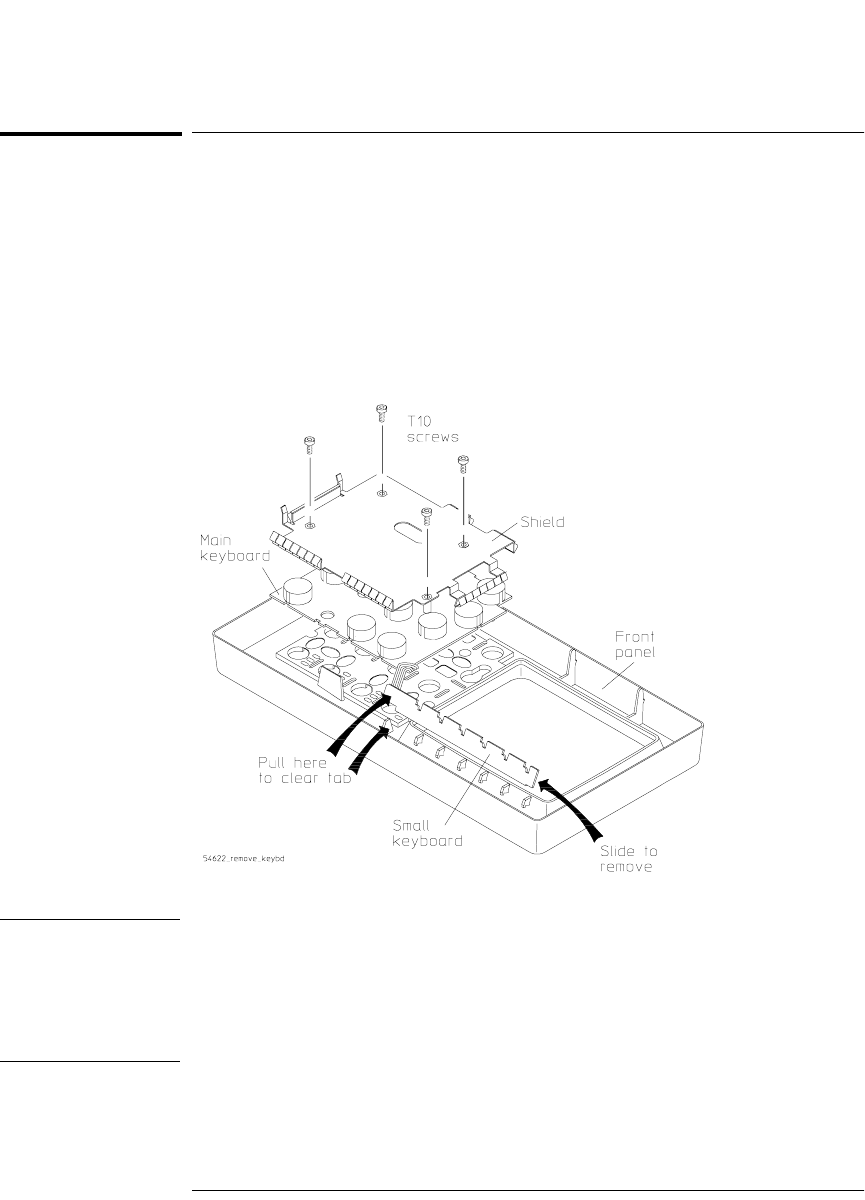
To remove the keyboard assembly
To remove the keyboard assembly
1 Remove the front panel.
2 Remove all of the knobs by pulling them straight out.
3 Using the T10 TORX driver, remove the four screws from the keyboard
shield.
4 Lift the ribbon cable end of the small keyboard and simultaneously slide
the small keyboard toward the main keyboard to remove.
Figure 6-12
Removing the keyboard assembly
CAUTION USE CORRECT SCREWS TO AVOID DAMAGING FRONT PANEL
LABEL!
When you re-install the keyboard, you must re-insert the screws you removed
in this step. If you re-insert screws that are longer, they can damage the front
panel label.
5 Lift the keyboard assembly straight out.
service.book Page 15 Wednesday, December 18, 2002 8:35 AM