
User's Manual


Table Of Contents
- Title page
- Contents
- 1 General Information
- 2 Preparing the Oscilloscope for Use
- 3 Testing Performance
- List of Test Equipment
- To construct the test connector
- To test the 54621D/22D Oscilloscope digital channels
- To verify digital channel threshold accuracy
- To verify voltage measurement accuracy
- To verify bandwidth
- To verify horizontal Dt and 1/Dt accuracy
- To verify trigger sensitivity
- Agilent 54622A/22D/24A Performance Test Record
- Agilent 54621A/21D Performance Test Record
- 4 Calibrating and Adjusting
- 5 Troubleshooting
- 6 Replacing Assemblies
- 7 Replaceable Parts
- Declaration of Conformity
- Notices
6-14
Replacing Assemblies
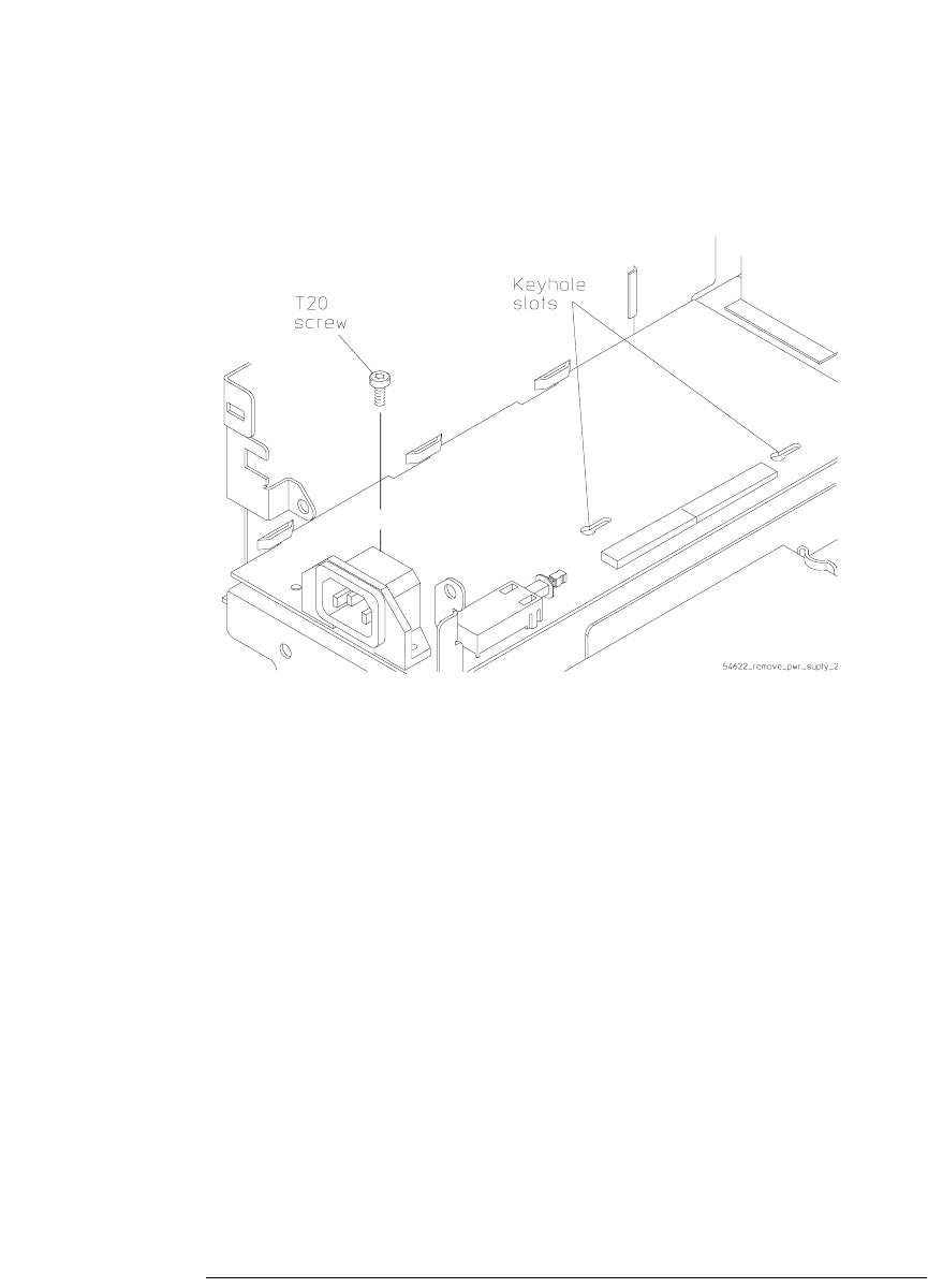
To remove the power supply
6
Using the T20 TORX driver, remove the screw holding the power supply
board to the deck.
Figure 6-11
Removing the power supply
7 Slide the power supply board toward the front panel about 1/2 inch. Slip
the power supply board keyhole slots off of the pins on the deck.
service.book Page 14 Wednesday, December 18, 2002 8:35 AM