
User's Manual


Table Of Contents
- Title page
- Contents
- 1 General Information
- 2 Preparing the Oscilloscope for Use
- 3 Testing Performance
- List of Test Equipment
- To construct the test connector
- To test the 54621D/22D Oscilloscope digital channels
- To verify digital channel threshold accuracy
- To verify voltage measurement accuracy
- To verify bandwidth
- To verify horizontal Dt and 1/Dt accuracy
- To verify trigger sensitivity
- Agilent 54622A/22D/24A Performance Test Record
- Agilent 54621A/21D Performance Test Record
- 4 Calibrating and Adjusting
- 5 Troubleshooting
- 6 Replacing Assemblies
- 7 Replaceable Parts
- Declaration of Conformity
- Notices
6-7
Replacing Assemblies
To remove the front panel
To remove the front panel
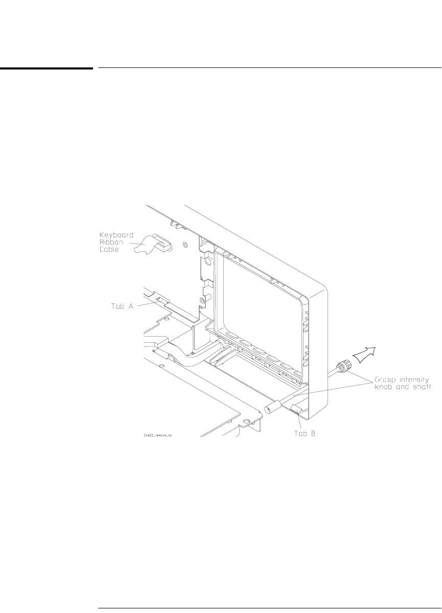
1 Remove the intensity knob and shaft by grasping the knob with one
hand and the grasping the shaft behind the front panel with the other
hand and pulling the shaft straight out from the front panel.
2 Disconnect the keyboard ribbon cable W2 from the keyboard.
3 Use a screwdriver to release retainer tab A, and your finger to release
retainer tab B. See the tab locations in Figure 6-4.
Figure 6-4
Removing the intensity shaft and front panel
4 Swing the front panel out until the bottom clears the deck assembly,
then lift it up to free the hooks on top and pull it away from the deck.
When installing the front panel, make sure that the power switch shaft is aligned
with the connection hole in the front panel to make a proper connection.
Before engaging the retainer tabs, make sure that all of the hooks on top of the
front panel are fully engaged with their connection holes in the sheet metal.
Then swing the front panel in to engage the two retainer tabs.
service.book Page 7 Wednesday, December 18, 2002 8:35 AM