
User's Manual


Table Of Contents
- Title page
- Contents
- 1 General Information
- 2 Preparing the Oscilloscope for Use
- 3 Testing Performance
- List of Test Equipment
- To construct the test connector
- To test the 54621D/22D Oscilloscope digital channels
- To verify digital channel threshold accuracy
- To verify voltage measurement accuracy
- To verify bandwidth
- To verify horizontal Dt and 1/Dt accuracy
- To verify trigger sensitivity
- Agilent 54622A/22D/24A Performance Test Record
- Agilent 54621A/21D Performance Test Record
- 4 Calibrating and Adjusting
- 5 Troubleshooting
- 6 Replacing Assemblies
- 7 Replaceable Parts
- Declaration of Conformity
- Notices
5-11
Troubleshooting
To check the Low Voltage Power Supply
To check the Low Voltage Power Supply
1 Disconnect the power cord from the oscilloscope. Then remove the
oscilloscope cover and set the oscilloscope on its side.
CAUTION USE AN EXTERNAL FAN TO AVOID OVERHEATING COMPONENTS !
If you operate the oscilloscope with the cabinet removed, you must use an
external fan to blow air across the system board. This external air flow is
necessary to cool the heat sinks on the system board. Otherwise, damage to
the components can occur.
2 Connect the negative lead of the multimeter to a ground point on the
oscilloscope. Connect the power cord and turn on the oscilloscope.
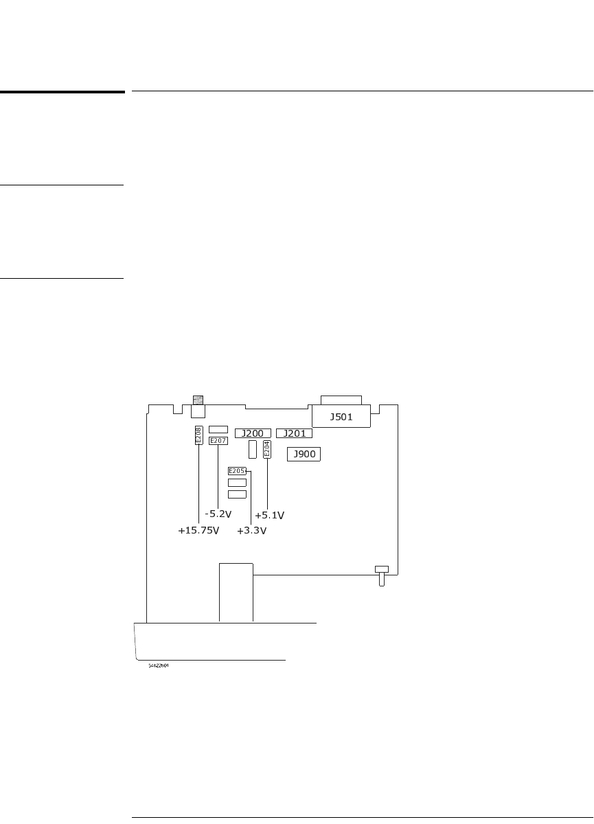
3 Measure the power supply voltages at E1 through E6 on the system
board. See Figure 5-3 and Table 5-4.
Figure 5-3
Low Voltage Power Supply Test Points
service.book Page 11 Wednesday, December 18, 2002 8:35 AM