
User's Manual

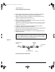


Table Of Contents
- Title page
- Contents
- 1 General Information
- 2 Preparing the Oscilloscope for Use
- 3 Testing Performance
- List of Test Equipment
- To construct the test connector
- To test the 54621D/22D Oscilloscope digital channels
- To verify digital channel threshold accuracy
- To verify voltage measurement accuracy
- To verify bandwidth
- To verify horizontal Dt and 1/Dt accuracy
- To verify trigger sensitivity
- Agilent 54622A/22D/24A Performance Test Record
- Agilent 54621A/21D Performance Test Record
- 4 Calibrating and Adjusting
- 5 Troubleshooting
- 6 Replacing Assemblies
- 7 Replaceable Parts
- Declaration of Conformity
- Notices

3-16
Testing Performance
To verify horizontal Dt and 1/Dt accuracy
4
Change the calibrator to 1-µs markers. Change the time base to
200 ns/div. Adjust the trigger level to obtain a stable display.
5 Measure the following:
Frequency 1 MHz — The test limits are 997.9 kHz to 1.002 MHz.
Period 1 µs — The test limits are 997.9 ns to 1.002 µs.
If the measurements are not within the test limits, see the “Troubleshooting”
chapter. Then return here.
54622A/22D/24A only
6
Change the calibrator to 10-ns markers. Change the time base to
5 ns/div. Adjust the trigger level to obtain a stable display.
7 Measure the following:
Frequency 100 MHz — The test limits are 99.10 MHz to 100.9 MHz.
Period 10 ns — The test limits are 9.91 ns to 10.09 ns.
If the measurements are not within the test limits, see the “Troubleshooting”
chapter. Then return here.
54621A and 54621D
only
8
Change the calibrator to 20 ns markers. Change the time base to 5 ns/div.
Adjust the trigger level to obtain a stable display.
9 Measure the following:
Frequency 50 MHz — The test limits are 49.77 MHz to 50.23 MHz.
Period 20 ns — The test limits are 19.91 ns to 20.09 ns.
If the measurements are not within the test limits, see the “Troubleshooting”
chapter. Then return here.
service.book Page 16 Wednesday, December 18, 2002 8:35 AM