
User's Manual


Table Of Contents
- Title page
- Contents
- 1 General Information
- 2 Preparing the Oscilloscope for Use
- 3 Testing Performance
- List of Test Equipment
- To construct the test connector
- To test the 54621D/22D Oscilloscope digital channels
- To verify digital channel threshold accuracy
- To verify voltage measurement accuracy
- To verify bandwidth
- To verify horizontal Dt and 1/Dt accuracy
- To verify trigger sensitivity
- Agilent 54622A/22D/24A Performance Test Record
- Agilent 54621A/21D Performance Test Record
- 4 Calibrating and Adjusting
- 5 Troubleshooting
- 6 Replacing Assemblies
- 7 Replaceable Parts
- Declaration of Conformity
- Notices
3-7
Testing Performance
To verify digital channel threshold accuracy
1
Turn on the test equipment and the oscilloscope. Let them warm up for
30 minutes before starting the test.
2 Set up the oscilloscope calibrator.
a Set the oscilloscope calibrator to provide a DC offset voltage at the
Channel 1 output.
b Use the multimeter to monitor the oscilloscope calibrator DC output
voltage.
3
Use either method 1 or method 2, described in the following, to connect
the digital channels for testing.
a Method 1 — Using the Test Connector
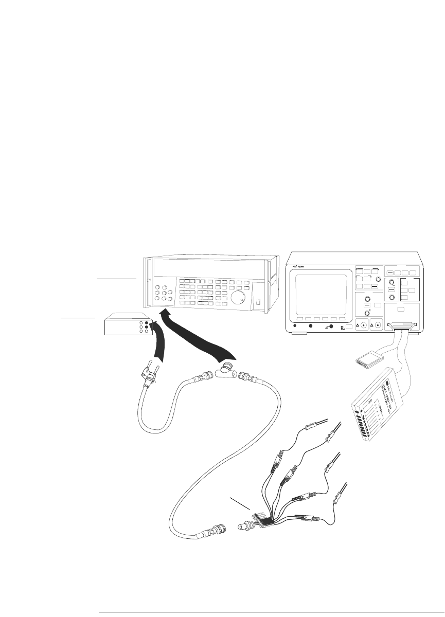
Use the 8-by-2 test connector and the BNC cable assembly to connect digital
channels D0-D7 to one side of the BNC Tee. Then connect the D0-D7 ground
lead to the ground side of the 8-by-2 connector. See figure 3-2.
Figure 3-2
Setting Up Equipment and Test Connector for the Threshold Test
Measure time
Save/Recall
Entry
Mixed Signal Oscilloscope
54620A
16 CHANNEL 500 MSa/s
STORA GE
TRIGGE RHORIZONTAL
CHANNEL
IN PU TS
Line
Time/D iv
Select
Trig ge r o u t
!
Delay
Positio n
Ext t rigge r in
!
!
t
hr
es
h.
cd
r
HP 34401A
Test
Connector
BNC-Banana
cable
Channels 8 - 15
Channels 0 - 7
Oscilloscope
Calibrator
Digital
Multimeter
service.book Page 7 Wednesday, December 18, 2002 8:35 AM