
User's Manual


Table Of Contents
- Title page
- Contents
- 1 General Information
- 2 Preparing the Oscilloscope for Use
- 3 Testing Performance
- List of Test Equipment
- To construct the test connector
- To test the 54621D/22D Oscilloscope digital channels
- To verify digital channel threshold accuracy
- To verify voltage measurement accuracy
- To verify bandwidth
- To verify horizontal Dt and 1/Dt accuracy
- To verify trigger sensitivity
- Agilent 54622A/22D/24A Performance Test Record
- Agilent 54621A/21D Performance Test Record
- 4 Calibrating and Adjusting
- 5 Troubleshooting
- 6 Replacing Assemblies
- 7 Replaceable Parts
- Declaration of Conformity
- Notices
2-13
Preparing the Oscilloscope for Use
To verify basic oscilloscope operation
To verify basic oscilloscope operation
1 Connect an oscilloscope probe to channel 1.
2 Attach the probe to the Probe Comp output on the lower-right side of
the front panel of the oscilloscope.
Use a probe retractable hook tip so you do not need to hold the probe.
3Press the Save/Recall key on the front panel, then press the Default Setup
softkey under the display.
The oscilloscope is now configured to its default settings.
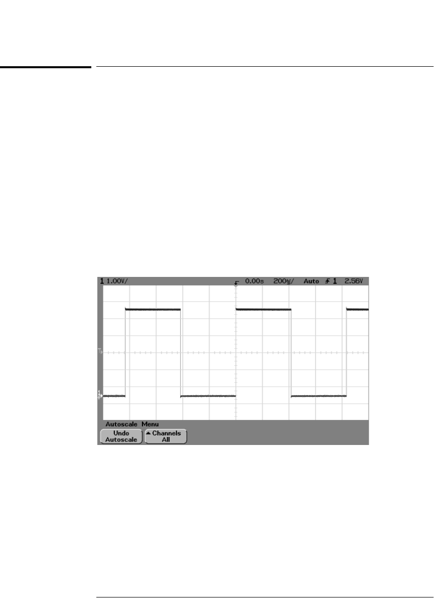
4Press the Autoscale key on the front panel.
You should then see a square wave with peak-to-peak amplitude of about 5
divisions and a period of about 4 divisions as shown below. If you do not see
the waveform, ensure your power source is adequate, the oscilloscope is
properly powered-on, and the probe is connected securely to the front-panel
channel input BNC and to the Probe Comp calibration output.
Verifying Basic Oscilloscope Operation
service.book Page 13 Wednesday, December 18, 2002 8:35 AM