
User's Manual


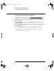
Table Of Contents
- Title page
- Contents
- 1 General Information
- 2 Preparing the Oscilloscope for Use
- 3 Testing Performance
- List of Test Equipment
- To construct the test connector
- To test the 54621D/22D Oscilloscope digital channels
- To verify digital channel threshold accuracy
- To verify voltage measurement accuracy
- To verify bandwidth
- To verify horizontal Dt and 1/Dt accuracy
- To verify trigger sensitivity
- Agilent 54622A/22D/24A Performance Test Record
- Agilent 54621A/21D Performance Test Record
- 4 Calibrating and Adjusting
- 5 Troubleshooting
- 6 Replacing Assemblies
- 7 Replaceable Parts
- Declaration of Conformity
- Notices
2-10
Preparing the Oscilloscope for Use
To use the digital probes (mixed-signal oscilloscope only)
5 For high-speed signals, connect a ground lead to the probe lead, connect
a grabber to the ground lead, and attach the grabber to ground in the
circuit under test.
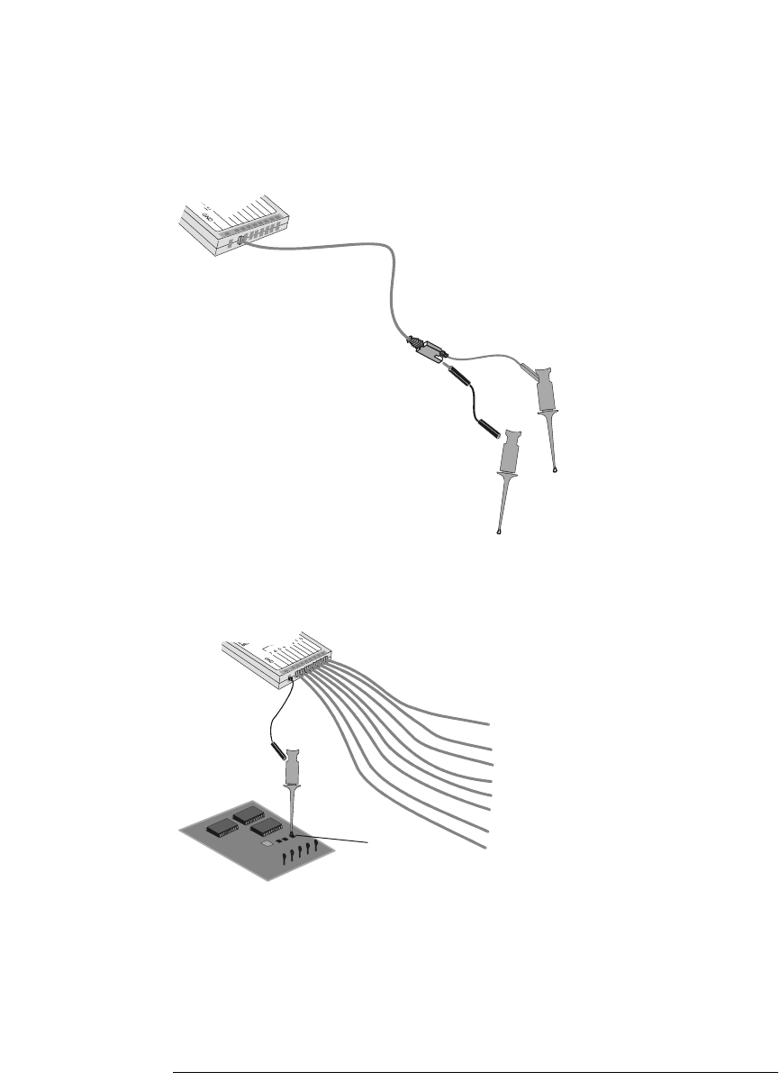
6 Connect the ground lead on each set of channels, using a probe grabber.
The ground lead improves signal fidelity to the instrument, ensuring
accurate measurements.
Signal Lead
Ground Lead
Grabber
Circuit
Ground
Channel
Pod Ground
service.book Page 10 Wednesday, December 18, 2002 8:35 AM