
User's Manual


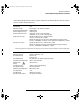


Table Of Contents
- Title page
- Contents
- 1 General Information
- 2 Preparing the Oscilloscope for Use
- 3 Testing Performance
- List of Test Equipment
- To construct the test connector
- To test the 54621D/22D Oscilloscope digital channels
- To verify digital channel threshold accuracy
- To verify voltage measurement accuracy
- To verify bandwidth
- To verify horizontal Dt and 1/Dt accuracy
- To verify trigger sensitivity
- Agilent 54622A/22D/24A Performance Test Record
- Agilent 54621A/21D Performance Test Record
- 4 Calibrating and Adjusting
- 5 Troubleshooting
- 6 Replacing Assemblies
- 7 Replaceable Parts
- Declaration of Conformity
- Notices
1-14
General Information
Analog Channel Triggering
Analog Channel Triggering
Range (Internal) ±6 div from center screen
Sensitivity* Greater of 0.35 div or 2.5 mV
Coupling AC (~3.5 Hz), DC, noise reject, HF reject and LF reject (~ 50 kHz)
Digital (D15 - D0) Channel Triggering (54621D and 5462 2D)
Threshold Range (user-defined) ±8.0 V in 10 mV increments
Threshold Accuracy* ±(100 mV + 3% of threshold setting)
Predefined Thresholds TTL = 1.4 V, CMOS = 2.5 V, ECL = -1.3 V
External (EXT) Triggering
Input Resistance 1 MΩ ±3%
Input Impedance ~ 14 pF
Maximum Input CAT I 300 Vrms, 400 Vpk
CAT II 100 Vrms, 400 Vpk
with 10074C 10:1 probe:CAT I 500 Vpk, CAT II 400 Vpk
Range ±10 V
Sensitivity dc to 25 MHz, < 75 mV
25 MHz to max bandwidth, < 150 mV
Coupling AC (~ 3.5 Hz), DC, noise reject, HF reject and LF reject (~ 50 kHz)
Probe ID (Agilent/HP & Tek
Compatible)
Auto probe sense for 54621A/22A
* Denotes Warranted Specifications, all others are typical. Specifications are valid after a 30-minute warm-up period and
±10 °C from firmware calibration temperature.
service.book Page 14 Wednesday, December 18, 2002 8:35 AM