User's Guide Agilent 83485A/B Optical/Electrical Plug-In Module
Agilent part number: 83485-90062 Printed in USA May 2000 Notice. The information contained in this document is subject to change without notice. Agilent Technologies makes no warranty of any kind with regard to this material, including but not limited to, the implied warranties of merchantability and tness for a particular purpose.
Safety Symbols CAUTION WARNING The following safety symbols are used throughout this manual. Familiarize yourself with each of the symbols and its meaning before operating this instrument. The caution sign denotes a hazard to the instrument. It calls attention to a procedure which, if not correctly performed or adhered to, could result in damage to or destruction of the instrument. Do not proceed beyond a caution sign until the indicated conditions are fully understood and met.
General Safety Considerations WARNING Before this instrument is switched on, make sure it has been properly grounded through the protective conductor of the ac power cable to a socket outlet provided with protective earth contact. Any interruption of the protective (grounding) conductor, inside or outside the instrument, or disconnection of the protective earth terminal can result in personal injury. WARNING There are many points in the instrument which can, if contacted, cause personal injury.
Assistance Product maintenance agreements and other customer assistance agreements are available for Agilent Technologies products. For assistance, contact your nearest Agilent Technologies Service O ce. Sales and service o ces Agilent Technologies has sales and service o ces located around the world to provide complete support for Agilent Technologies products. To obtain servicing information or to order replacement parts, contact the nearest Agilent Technologies Sales and Service O ce.
Agilent Technologies Service Numbers Austria Belgium Brazil China Denmark Finland France Germany India Italy Ireland Japan Korea Mexico Netherlands Norway Russia Spain Sweden Switzerland United Kingdom United States and Canada vi 01/25125-7171 32-2-778.37.71 (11) 7297-8600 86 10 6261 3819 45 99 12 88 358-10-855-2360 01.69.82.66.
Warranty This Agilent Technologies instrument product is warranted against defects in material and workmanship for a period of one year from date of shipment. During the warranty period, Agilent Technologies will, at its option, either repair or replace products which prove to be defective. For warranty service or repair, this product must be returned to a service facility designated by Agilent Technologies.
Contents . . . . . . . . . . . . . . v Ordering information . . . . . . . . . . . . . . . . Menu and Key Conventions . . . . . . . . . . . . . . The Agilent 83485A/B Optical/Electrical Plug-In Module Front panel of the plug-in module . . . . . . . . . . Getting the best performance . . . . . . . . . . . . Installing the plug-in module . . . . . . . . . . . . Trigger . . . . . . . . . . . . . . . . . . . . . . Cleaning Connections for Accurate Measurements . . . . To clean a non-lensed connector . . . . .
Channel Skew Calibration . . . . . . . . . . . . . Probe Calibration . . . . . . . . . . . . . . . . . . . External Scale . . . . . . . . . . . . . . . . . . Complete Calibration Summary . . . . . . . . . . . . 4. Speci cations and Regulatory Information 3-15 3-16 3-18 3-20 . . . . . . 4-3 4-3 4-9 4-10 4-10 4-11 If the mainframe does not operate . . . . . . . . . . . If the plug-in does not operate . . . . . . . . . . . . Error Messages . . . . . . . . . . . . . . . . . . .
Figures 1-1. 2-1. 2-2. 2-3. 3-1. 3-2. 3-3. 3-4. 3-5. 3-6. Front panel of the plug-in module. Optical Channel Setup menu. . . . Electrical Channel Setup menu. . . A typical Cal Status display. . . . Current Frame 1Temp condition . Plug-in calibration menu . . . . . O set Zero Calibration . . . . . . Dark calibration menu . . . . . . Electrical Channel Calibrate Menu . External Scale Menu . . . . . . . . . . . . . . . . . . . . . . . . . . . . . . . . . . . . . . . . . . . . . . . . . . . . . . . . .
Contents
1 The Instrument at a Glance
The Instrument at a Glance What you'll nd in this chapter This chapter describes: options and accessories the key conventions used in this manual the front panel, rear panel and keys that do not display menus on the screen lightwave connector care Understanding the information in this chapter will help you successfully operate the instrument. CAUTION The input circuits can be damaged by electrostatic discharge (ESD).
The Instrument at a Glance channel is calibrated at 1310 nm and 1550 nm to provide both accurate display of the received optical waveform in optical power units and measurement of the signal's average power. In addition, the User Cal feature provides for consistent accuracy at any wavelength between 1200 nm and 1600 nm using a source and power meter.
Ordering information Agilent 83485A options Option 030 Built-in STM-1/OC-3 155 Mb/s SDH/SONET reference receiver Option 032 Built-in STM-4/OC-12 622 Mb/s SDH/SONET reference receiver Option 034 Built-in STM-16/OC-48 2.
The Instrument at a Glance Ordering information Optional accessories Agilent 54006A 6 GHz divider probe Agilent 54008A 22 ns delay line Agilent 54118A 500 MHz to 18 GHz trigger Agilent 10086A ECL terminator SMA (f-f) adapter, Agilent part number 1250-1158 SMA 50 termination, Agilent part number 1810-0118, 1 each APC 3.5 (f-f) adapter, Agilent part number 1250-1749 APC 2.4 (f-f) adapter, Agilent 11900B APC 2.4 to 3.
Menu and Key Conventions The keys labeled Trigger, Disk, and Run are all examples of front-panel keys. Pressing some front-panel keys accesses menus of functions that are displayed along the right side of the display screen. These menus are called softkey menus. Softkey menus list functions other than those accessed directly by the front-panel keys. To activate a function on the softkey menu, press the unlabeled key immediately next to the annotation on the screen.
The Instrument at a Glance Menu and Key Conventions value, use the general purpose knob located below the front-panel Measure section.
The Agilent 83485A/B Optical/Electrical Plug-In Module The Agilent 83485A/B optical/electrical plug-in modules are two of several plug-in modules available for the Agilent 83480A, 54750A mainframes. Their main features are: Integrated, calibrated optical channel. Optical channel includes switchable SONET/SDH lter. Electrical measurement channel. 2.5 GHz trigger channel. Both optical and electrical measurement channels have user selectable bandwidths of 12.4 or 20 GHz.
The Instrument at a Glance The Agilent 83485A/B Optical/Electrical Plug-In Module The purpose of the plug-in module is to provide measurement channels, including sampling, for the mainframe. The plug-in module scales the input signal, sets the bandwidth of the system, and allows the o set to be adjusted so the signal can be viewed. The output of the plug-in module is an analog signal that is applied to the ADCs on the acquisition boards inside the mainframe.
The Instrument at a Glance The Agilent 83485A/B Optical/Electrical Plug-In Module Front panel of the plug-in module The plug-in module takes up two of the four mainframe slots. The optical channel provides calibrated measurement of optical waveforms in power units. Bandwidths are selectable on both channels to optimize sensitivity and bandwidth. The front panel of the plug-in module has two channel inputs and an external trigger input.
The Instrument at a Glance The Agilent 83485A/B Optical/Electrical Plug-In Module Getting the best performance To ensure you obtain the speci ed accuracy, you must perform a plug-in module vertical calibration. The calibration must also be performed when you move a plug-in module from one slot to another, or from one mainframe to another. Refer to Chapter 3 for information on performing a plug-in module vertical calibration.
The Instrument at a Glance The Agilent 83485A/B Optical/Electrical Plug-In Module To use the plug-in module, the Agilent 83480A/54750A rmware revision 3.0 or higher is required. The plug-in module can be installed in slots 1 and 2 or 3 and 4 on the Agilent 83480A, 54750A mainframe. The plug-in module will not function if it is installed in slots 2 and 3. To make sure the analyzer meets all of the published speci cations, there must be a good ground connection from the plug-in module to the mainframe.
Cleaning Connections for Accurate Measurements CAUTION Accurate and repeatable measurements require clean connections. Use the following guidelines to achieve the best possible performance when making measurements on a ber-optic system: Keep connectors covered when not in use. Use dry connections whenever possible. Use the cleaning methods described in this section. Use care in handling all ber-optic connectors.
The Instrument at a Glance Cleaning Connections for Accurate Measurements Dust Caps Provided with Lightwave Instruments Item Laser shutter cap FC/PC dust cap Biconic dust cap DIN dust cap HMS10 dust cap ST dust cap Agilent Part Number 08145-64521 08154-44102 08154-44105 5040-9364 5040-9361 5040-9366 Inspecting Fiber-Optic Consistent measurements with your lightwave equipment are a good indication that you have good connections.
The Instrument at a Glance Cleaning Connections for Accurate Measurements To clean a non-lensed connector CAUTION Do not use any type of foam swab to clean optical ber ends. Foam swabs can leave lmy deposits on ber ends that can degrade performance. 1. Apply isopropyl alcohol to a clean lint-free cotton swab or lens paper. Cotton swabs can be used as long as no cotton bers remain on the ber end after cleaning. 2. Before cleaning the ber end, clean the ferrules and other parts of the connector. 3.
The Instrument at a Glance Cleaning Connections for Accurate Measurements To clean an adapter 1. Apply isopropyl alcohol to a clean foam swab. Cotton swabs can be used as long as no cotton bers remain after cleaning. The foam swabs listed in this section's introduction are small enough to t into adapters.
The Instrument at a Glance To test return loss Use an appropriate lightwave source, a lightwave receiver, and lightwave coupler to test return loss.
The Instrument at a Glance
2 Channel Setup Menu
Channel Setup Menu What you'll nd in this chapter This chapter describes the Channel Setup menu. A key tree and description of the available functions is included. CAUTION The input circuits can be damaged by electrostatic discharge (ESD). Therefore, avoid applying static discharges to the front-panel input connectors. Before connecting any coaxial cable to the connectors, momentarily short the center and outer conductors of the cable together.
Channel Setup Menu Figure 2-1. Optical Channel Setup menu.
Channel Setup Menu Figure 2-2. Electrical Channel Setup menu. Displaying the Channel Setup menus To display the optical Channel Setup menu, press the optical 4Channel5 key.
Channel Setup Menu To display the electrical Channel Setup menu, press the electrical 4Channel5 key. Display aaaaaaaaaaaaaaaaaaaaaaaaaaaaaaaaaaaa The Display function turns the channel display o and on. When the channel display is on, a waveform is displayed for that channel, unless the o set is adjusted so the waveform is clipped o of the display. The channel number, vertical scaling, and o set are displayed at the bottom left of the waveform area.
Channel Setup Menu Scale aaaaaaaaaaaaaaaaaaaaaaaaaa The Scale softkey controls the vertical scaling of the waveform. If the ne mode is o , then the knob and arrow keys change the vertical scaling in a 1-2-5 sequence. When ne mode is on, the knob and arrow keys change the vertical scaling in 1 mV increments. You can also use the keypad to enter values in 1 mV increments, independent of the ne mode selection.
Channel Setup Menu Offset aaaaaaaaaaaaaaaaaaaaaaaaaaaaaaa The O set softkey moves the waveform vertically. It is similar to the position control on analog oscilloscopes. The advantage of digital o set is that it is calibrated. The o set voltage for electrical channels is the voltage at the center of the graticule area, and the range of o set is 612 times the full resolution channel scale. For optical channels, the o set wattage is the wattage two graticule divisions above the bottom of the screen.
Channel Setup Menu NNNNNNNNNNNNNNNNNNNNNNNNNNNNN Bandwidth Agilent 83485A: This function is available on the electrical channel and on the optical channel only when the lter is switched o . You can use the Bandwidth function to select either the 12.4 GHz or the 20 GHz bandwidth. Agilent 83485B: This function is available on the electrical channel only. You can use the Bandwidth function to select either the 18 GHz or 40 GHz bandwidth.
Channel Setup Menu Channel autoscale aaaaaaaaaaaaaaaaaaaaaaaaaaaaaaaaaaaaaaaaaaaaaaaaaaaaaaaaaaaaaaaaaaaaaaaaaaaaaaaaaaa The Channel Autoscale function provides a convenient and fast method for determining the standard vertical scale setting with the highest resolution that will not clip the waveform. Timebase and trigger settings are not a ected.
Channel Setup Menu NNNNNNNNNNNNNNNNNNNNNNNNNNNNNNNNNNN Attenuation The Attenuation function lets you select an attenuation that matches the device connected to the analyzer. When the attenuation is set correctly, the analyzer maintains the current scale factors if possible. All marker values and voltage or wattage measurements will re ect the actual signal at the input to the external device. The attenuation range is from 0.0001:1 to 1,000,000:1.
Channel Setup Menu Ext gain and Ext offset NNNNNNNNNNNNNNNNNNNNNNNNNN NNNNNNNNNNNNNNNNNNNNNNNNNNNNNNNN Key Path When you select Ampere, Watt, or unknown on an electrical channel or Voltage on an optical channel, two additional functions become available: External Gain and External O set. These two additional functions allow you to compensate for the actual characteristics of the probe rather than its ideal characteristics.
Channel Setup Menu NNNNNNNNNNNNNN Skew The Skew function changes the horizontal position of a waveform on the display. The Skew function has a range of +100 s. You can use skew to compensate for di erences in cable or probe lengths. It also allows you to place the triggered edge at the center of the display when you are using a power splitter connected between the channel and trigger inputs. Another use for skew is when you are comparing two waveforms that have a timing di erence between them.
Channel Setup Menu Cal status The Cal Status function displays a screen similar to Figure 2-3. Key Path 4Channel5 NNNNNNNNNNNNNNNNNNNNNNNNNNNNNNNN NNNNNNNNNNNNNNNNNNNNNNNNNNNNN NNNNNNNNNNNNNNNNNNNNNNNNNNNNNNNN Calibrate Cal Status Figure 2-3. A typical Cal Status display. Current Date This is the current date and time. You can compare this to the last plug-in module calibration time. That way you will know how long it has been since the last plug-in module calibration was performed.
Channel Setup Menu Channel 1 Calibration Status The instrument displays Calibrated or Uncalibrated, depending on whether the last plug-in module calibration is still valid. A calibration can be invalidated if: The mainframe has cycled power. The plug-in has been repaired, reprogrammed, or removed from the mainframe. The instrument's operating temperature has changed and remains more than 5 C from the temperature at which the Plug-in calibration was performed.
Channel Setup Menu Calibrate probe Connect a voltage probe to the plug-in and then press: NNNNNNNNNNNNNNNNNNNNNNNNNNNNNNNNNNNNNNNNNNNNNNN NNNNNNNNNNNNNNNNNNNNNNNNNNNNNNNNNNNNNNNNNNNNNNN Calibrate probe The analyzer calibrates to the tip of the probe by setting the probe attenuation to the actual attenuation ratio of the probe. The analyzer also automatically compensates for any o set the probe may introduce. The CAL signal is internally routed to the probe tip for Agilent probes.
Channel Setup Menu
3 Calibration Overview
Calibration Overview What you'll nd in this chapter Factory Calibrations User Calibrations|Optical and Electrical Complete Calibration This chapter describes the calibration of the mainframe and the plug-in modules. It is intended to give you, or the calibration laboratory personnel, an understanding of the various calibration procedures available, and how they were intended to be used. There is a description of the calibration menu included in the manuals provided with the plug-in modules and probes.
Calibration Overview CAUTION Calibration interval performed regularly in order to ensure proper measurement accuracy and repeatability. The input circuits can be damaged by electrostatic discharge (ESD). Avoid applying static discharges to the front-panel input connectors. Before connecting a coaxial cable to the connectors, momentarily short the center and outer connectors of the cable together. Avoid touching the front panel input connectors without rst touching the frame of the instrument.
Factory Calibrations The following calibrations are performed at the factory: Mainframe Calibration O/E Factory Wavelength Calibration Table 3-1.
Calibration Overview Factory Calibrations CAUTION The calibration factors are stored in the nonvolatile RAM of the instrument. There is a switch on the back panel of the instrument that allows the mainframe calibration to be protected or unprotected. Next to the switch there is a drawing that shows each switch's function and protected position.
Calibration Overview Factory Calibrations If the Current Frame 1Temp listing is greater than 65 C, then the mainframe should either be calibrated at the current operating temperature or be placed in an ambient air temperature that is within 5 C of the temperature of the current calibration. O/E Factory Wavelength Calibration Optical/electrical (O/E) factory wavelength calibration, compensates for the photodetector responsivity.
User Calibrations|Optical and Electrical The following calibrations can be performed by the user: O/E User Wavelength Calibration Plug-in Module Vertical Calibration O set Zero Calibration Dark Calibration Probe Calibration Channel Skew External Scale Electrical channels have calibration procedures for: adjusting timebase skew, for matching propagation delay between channels, probes, cables, and so forth using external probes Optical channels have calibration procedures for: adjusting timebase skew
Calibration Overview User Calibrations|Optical and Electrical Table 3-2. Optical and Electrical Channel User Calibration Summary Calibration What is calibrated Measurements A ected Channels a ected: optical. All Annual re-calibration of user optical channel measurements de ned non-factory wavelengths at user wavelengths. O/E User Wavelength Calibration The photodetector responsivity Plug-in Vertical Calibration Channels a ected: optical & electrical.
Calibration Overview User Calibrations|Optical and Electrical Table 3-3. Miscellaneous User Calibration Summary Calibration Probe calibration What is calibrated Probe Attenuation Channel Skew Calibrates out the small di erences in delay between channels.
Calibration Overview User Calibrations|Optical and Electrical NOTE The optical channel calibration accuracy is heavily dependent on the accuracy to which you know the optical source power. For best results, measure the optical source power with an optical power meter such as the Agilent 8153A and use precision optical connectors. In addition, proper connector cleaning procedures are essential to obtaining an accurate calibration. To perform an O/E user-wavelength calibration 1.
Calibration Overview User Calibrations|Optical and Electrical To use an O/E user-wavelength calibration 1. Press the plug-in module's front-panel optical channel 4SETUP5 key. 2. Press Bandwidth/wavelength and then Wavelength . NNNNNNNNNNNNNNNNNNNNNNNNNNNNNNNN NNNNNNNNNNNNNNNNNNNNNNNNNNNNNNNNNNNNNNNNNNNNNNNNNNNNNNNNNNNNNN 3. Press Usr wavelength and then Enter .
Calibration Overview User Calibrations|Optical and Electrical To perform a plug-in module vertical calibration 1. Remove any front-panel connections from electrical channels. 2. Cover the optical inputs for the optical channels. 3. Press 4Utility5, Calibrate. . . , and then Calibrate plug-in. . . . NNNNNNNNNNNNNNNNNNNNNNNNNNNNNNNNNNNNNNNNNNNN NNNNNNNNNNNNNNNNNNNNNNNNNNNNNNNNNNNNNNNNNNNNNNNNNNNNNNNNNNNNNNNNNNNN 4. Select the plug-in module to be calibrated, press 1 and 2 or 3 and 4 .
Calibration Overview User Calibrations|Optical and Electrical To initiate an o set calibration 1. 2. 3. 4. Disconnect all inputs from the module being calibrated. Cover all optical inputs. Press the plug-in module's front-panel optical channel 4SETUP5 key. Press Calibrate and then Offset zero . NNNNNNNNNNNNNNNNNNNNNNNNNNNNN NNNNNNNNNNNNNNNNNNNNNNNNNNNNNNNNNNN Figure 3-3.
Calibration Overview User Calibrations|Optical and Electrical Dark Calibration The dark calibration is for optical measurements, or electrical measurements if an external O/E is being used. This calibration measures the optical channel o set signal when there isn't any light present and then uses this information in performing extinction ratio measurements.
Calibration Overview User Calibrations|Optical and Electrical Figure 3-4. Dark calibration menu Channel Skew Calibration This calibration a ects both optical and electrical measurements. The skew calibration changes the horizontal position of a waveform on the display. The skew calibration has a range of approximately 100 s. You can use skew to compensate for the di erences in cable or probe lengths.
Calibration Overview User Calibrations|Optical and Electrical To skew two channels 1. Turn both channels on and overlay the signals vertically. 2. Expand the time base so that the rising edges are at about a 45 angle. 3. Press the plug-in module's front-panel channel 4SETUP5 key. 4. Press Calibrate and then Skew . NNNNNNNNNNNNNNNNNNNNNNNNNNNNN NNNNNNNNNNNNNN 5. Adjust the skew on one of the channels so that the rising edges overlap at the 50% points.
Calibration Overview User Calibrations|Optical and Electrical 2. Press External scale and then Attenuation . You can use the probe calibration to calibrate any network, including probes or cable assemblies. The instrument calibrates the voltage at the tip of the probe or the cable input. NNNNNNNNNNNNNNNNNNNNNNNNNNNNNNNNNNNNNNNNNNNN NNNNNNNNNNNNNNNNNNNNNNNNNNNNNNNNNNN To calibrate an Agilent 1. Press the plug-in module's front-panel-channel 4SETUP5 key. identi able probe 2.
Calibration Overview User Calibrations|Optical and Electrical To calibrate other devices The information in this section applies to both optical and electrical measurements. Since the mainframe's CAL signal is a voltage source, it cannot be used to calibrate to the probe tip when the units are set to Ampere, Watt, or Unknown. Instead, set the external gain and external o set to compensate for the actual characteristics of the probe or device.
Calibration Overview User Calibrations|Optical and Electrical Figure 3-6.
Complete Calibration Summary Table 3-4. Complete Calibration Summary Calibration Mainframe Calibration What is calibrated Measurements A ected Accuracy and continuity of the timescale Channels a ected: optical & electrical. All time base measurements such as rise time, fall time, eye width, and jitter.
Calibration Overview Table 3-4. Complete Calibration Summary (continued) Calibration O set Zero Calibration Dark Calibration Probe calibration What is calibrated Vertical o set is calibrated for the optical channel only. This calibration doesn't include vertical scale accuracy. Dark calibration measures the channel o set signal without any light present and this value is used in the extinction ratio algorithm.
Calibration Overview
4 Speci cations and Regulatory Information
Speci cations and Regulatory Information This chapter lists the system speci cations and characteristics of the Agilent 83485A/B optical/electrical plug-in module when it is combined with either the Agilent 83480A or Agilent 54750A mainframes. The speci cations and characteristics for the mainframe are in the Agilent 83480A, 54750A User's Guide.
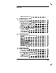
Speci cations The following are speci cations used to test the Agilent 83485A/B plug-in module. Speci cations are valid after a 1 hour warm-up period. See the Agilent 54701A Active Probe Service Guide for complete probe speci cations. Vertical speci cations Agilent 83485A Electrical Channel Vertical Speci cations Bandwidth (03 dB) on electrical or optical channel dc Accuracy|single marker1 12.4 GHz bandwidth 20 GHz dc to 12.4 or 20 GHz, user selectable 60.4% of full scale 62 mV 61.
Speci cations and Regulatory Information Speci cations Agilent 83485A Electrical Channel Vertical Speci cations (continued) Transition Time (10%{90%) characteristic, calculated from T=0.35/BW, electrical 12.4 GHz 20 GHz Maximum RMS Noise 12.4 GHz 20 GHz Scale Factor Minimum Maximum dc O set Range Nominal Input Impedance Connectors Input Re ection/Return Loss Number of Channels Dynamic Range/Maximum Speci ed Input Power Maximum Safe Input 4-4 28.2 ps 17.5 ps 0.5 mV (0.25 mV typical) 1.0 mV (0.
Speci cations and Regulatory Information Speci cations Agilent 83485A Optical Channel Vertical Speci cations Bandwidth (03 dB) on electrical or optical channel dc Accuracy|single marker1 12.4 GHz, ltered2 20 GHz2 dc to 12.4 or 20 GHz (user selectable) 625 W 62% (reading 0 channel o set) 6 (2%/ C) (1Tcal3 ) (reading) 0 0.4%/hr (1Time4 ) (reading) 625 W 64% (reading 0 channel o set) 6 (2%/ C) (1Tcal3 ) (reading) 0 0.
Speci cations and Regulatory Information Speci cations Agilent 83485A Optical Channel Vertical Speci cations (continued) Filtered Response Calibrated Wavelengths Average power Monitor Speci ed Operating Range Factory Calibrated Accuracy (20 C{30 C) User Calibrated Accuracy1 <5 C temp change Number of Channels Dynamic Range/Maximum Speci ed Input Power Maximum Safe Input Wavelength Range 1 Measured response conforms to ITU-TS G.
Speci cations and Regulatory Information Speci cations Agilent 83485B Electrical Channel Vertical Speci cations Bandwidth (03 dB) dc Accuracy|single voltage marker1 18 GHz 40 GHz Transition Time (10% to 90%, calculated from T=0.35/bandwidth) Maximum RMS Noise 18 GHz 40 GHz Scale Factor (full scale is eight divisions) Minimum Maximum dc O set Range Inputs: Dynamic Range Maximum Safe Input Voltage Nominal Impedance Re ections Connector dc to 40 GHz, or dc to 18 GHz (user selectable) 60.
Speci cations and Regulatory Information Speci cations Agilent 83485B Optical Channel Vertical Speci cations Bandwidth (03 dB) dc Accuracy1 (Optical channel referenced to average power meter) dc Di erence1 (two marker accuracy, same channel, referenced to average power monitor) Transition Time (10% to 90%) characteristic, calculated from T=0.
Speci cations and Regulatory Information Speci cations Environmental speci cations Temperature Operating Non-operating Humidity Operating Non-operating Electrical and Optical Channels 15 C to +35 C 040 C to +70 C up to 90% relative humidity (non-condensing) at 35 C up to 95% relative humidity (non-condensing) at 65 C Power Requirements Supplied by mainframe. Weight Net Shipping approximately 1.2 kg (2.6 lb.) approximately 2.1 kg (4.6 lb.
Characteristics The following characteristics are typical for the Agilent 83485A/B optical/electrical plug-in module. See the Agilent 54701A Active Probe Service Guide for complete probe characteristics. Trigger input characteristics Electrical and Optical Channels Nominal Impedance Input Connector Trigger Level Range Maximum Safe Input Voltage Percent Re ection 50 3.
Declaration of Conformity 4-11
Speci cations and Regulatory Information
5 In Case of Di culty
In Case of Di culty What you'll nd in this chapter This chapter provides a list of suggestions for you to follow if the plug-in module fails to operate. A list of messages that may be display is also included. For complete service information, refer to the optional . Agilent 83485A/B Service Guide Review the procedure being performed when the problem occurred.
In Case of Di culty If the mainframe does not operate If the mainframe does not operate Please make the following checks: Is the line fuse good? Does the line socket have power? Is the unit plugged in to the proper ac power source? Is the mainframe turned on? Is the rear-panel line switch set to on? Will the mainframe power up without the plug-in module installed? If the mainframe still does not power up, refer to the optional Agilent 83480A, 54750A Service Guide or return the mainframe to a quali ed ser
In Case of Di culty If the plug-in does not operate 1. Make the following checks: Is the plug-in module rmly seated in the mainframe slot? Are the knurled screws at the bottom of the plug-in module nger-tight? Is a trigger signal connected to a trigger input? If other equipment, cables, and connectors are being used with the plug-in module are they connected properly and operating correctly? Review the procedure for the test being performed when the problem appeared.
In Case of Di culty If the plug-in does not operate Make sure the mainframe identi es the plug-in module by pressing: 4Utility5 NNNNNNNNNNNNNNNNNNNNNNNNNNNNNNNNNNNNNNNNNNNNNNNNNN System config... The calibration status of the plug-in modules is listed near the bottom of the display, in the box labeled \Plug-ins". If the model number of the plug-in module is listed next to the appropriate slot number, then the mainframe has identi ed the plug-in.
In Case of Di culty Error Messages The following error messages are for the plug-in module. Typically, the error messages indicate there is a problem with either the plug-in or the mainframe. This section explains what the messages mean and o ers a few suggestions that might help resolve the error condition. If the suggestions do not eliminate the error message, then additional troubleshooting is required that is beyond the scope of this book.
In Case of Di culty Communication failure An illegal hardware state is detected at the mainframe to plug-in module exists at slot : Service interface of the speci ed slot. is required If the slot is empty, there is a mainframe hardware problem. Refer to the Agilent 83480A, 54750A Service Guide. If a plug-in is installed in the slot, there is a plug-in module hardware problem. Refer to the optional Agilent 83485A/B Service Guide.
In Case of Di culty
Index
Index A B C accessories connection devices, 1-5 optional, 1-5 accuracy performance, 1-11 active probe, 2-7 Agilent Technologies Sales and Service O ces, v attenuation range, 2-10 Attenuation softkey, 2-10 attenuator scaling, 2-9 Atten units softkey, 2-9 automatic measurement, 2-5 auxiliary power connector, 1-10 Bandwidth key, 2-8 Bandwidth/Wavelength . . .
channel display, 2-5 electrical, 1-2 input, 1-10 optical, 1-2 scale, 2-10 setup, 2-2 Channel 1 Calibration Status message, 2-14 Channel autoscale softkey, 2-9 Channel key, 2-2 characteristics, 4-10 cleaning adapters, 1-16 non-lensed connectors, 1-15 cleaning ber-optic connections, 1-13, 1-15 connection devices, 1-5 connector care, 1-13 Current Date message, 2-13 Current Frame 1Temp message, 2-13 customer assistance, v D E decibel calculation, 2-9 declaration of conformity, 4-10 description of the plug-in
F H I K M O factory calibration, 3-4 ber-optic cables cleaning connections, 1-13 inspecting, 1-14 front panel overview, 1-10 horizontal waveform, 2-12 index-matching compounds, 1-13 index matching gel, 1-13 input connector, 1-13 inspecting cables, 1-14 installing the plug-in module, 1-11 key conventions, 1-6 mainframe calibration, 3-4 mainframe troubleshooting, 5-3 marker value, 2-10 math function, 2-5 menu overview, 1-6 O/E calibration, 3-6 O/E cal softkey, 2-14 O/E converter calibration, 3-15 O/E user
P R S T plug-in message, 2-14 plug-in module description, 1-2 features, 1-8 front panel, 1-10 installation, 1-11 purpose, 1-8 speci cations, 4-3{9 troubleshooting, 5-4 weight, 4-9 plug-in module vertical calibration, 3-11 power level, 2-7 power requirements, 4-9 probe attenuation, 2-10, 2-15 attenuation factor, 2-9 characteristics, 2-11 power, 2-7 power connector, 1-10 probe calibration, 3-15, 3-16 pulse parameter measurements, 2-5 RF connectors, 1-11 safety information, iv, 1-12 sales and service o ces,
U V W Units softkey, 2-6, 2-10 user calibrations, 3-7 vertical calibration, 1-11 measurement, 2-10 scale, 2-5{6, 2-9 speci cations, 4-3 waveform, 2-7 voltage measurement, 2-10 probe, 2-15 voltage probe calibration, 3-16 warranty information, vii wattage measurement, 2-10 waveform display, 2-5 horizontal, 2-12 Wavelength key, 2-8 wavelength settings, 2-7 weight of plug-in module, 4-9 Index-6