User’s Guide Agilent 16440A SMU/Pulse Generator Selector Agilent Part No.
Legal Notice The information contained in this document is subject to change without notice. Copyright © 1994 - 2000 Agilent Technologies This document contains information which is protected by copyright. All rights are reserved. Reproduction, adaptation, or translation without prior written permission is prohibited, except as allowed under the copyright laws.
To the extent allowed by local law, the above warranties are exclusive and no other warranty or condition, whether written or oral, is expressed or implied and Agilent Technologies specifically disclaim any implied warranties or conditions of merchantability, satisfactory quality, and fitness for a particular purpose.
• GROUND THE INSTRUMENT This is Safety Class I instrument. To minimize shock hazard, the instrument chassis and cabinet must be connected to an electrical ground. The power terminal and the power cable must meet International Electrotechnical Commission (IEC) safety standards. • DO NOT OPERATE IN AN EXPLOSIVE ATMOSPHERE Do not operate the instrument in the presence of flammable gases or fumes. Operation of any electrical instrument in such an environment constitutes a definite safety hazard.
• Safety Symbols The general definitions of safety symbols used on equipment or in manuals are listed below. Instruction manual symbol: the product will be marked with this symbol when it is necessary for the user to refer to the instruction manual in order to protect against damage to the instrument. Indicates dangerous voltage and potential for electrical shock. Do not touch terminals that have this symbol when instrument is on. Protective conductor terminal.
• Herstellerbescheinigung GEÄUSCHEMISSION Lpa < 70 dB am Arbeitsplatz normaler Betrieb nach DIN 45635 T.
User's Guide Agilent 16440A User’s Guide, Edition 4
User's Guide Agilent 16440A SMU/Pulse Generator Selector is one of the accessories available for Agilent 4155/4156 Semiconductor Parameter Analyzers. The selector is for automatically switching the unit (SMU or PGU) that is connected to a DUT pin according to the state (stress force state or measurement state). NOTE To use the selector, the 4155/4156 must be equipped with Agilent 41501 SMU/pulse generator expander that contains two PGUs. This manual consists of the following sections.
User's Guide Introduction Introduction The 16440A selector contains the following accessories: Description Agilent Part Number Quantity 1 SMU/Pulse Generator Selector 16440A 1 2 40 cm triaxial cable 04155-61605 2 3 (option 001) 1.
User's Guide Operation Operation This section describes the operating theory of the selector. Agilent 4155/4156 can control the selector to automatically switch the unit (SMU or PGU) that is connected to a DUT pin according to the state (stress force state or measurement state). This is useful for performing reliability testing (stress testing) of DUTs. For example, the selector can connect a PGU to the DUT for forcing ac stress, then can switch and connect an SMU for measuring dc characteristics.
User's Guide Operation The following figure shows a simple circuit diagram of the selector (selector expander). The CH 1 and CH 3 circuits are different from the CH 2 and CH 4 circuits. Each channel has one mechanical relay for SMU and one mechanical relay for PGU, but the CH 1 and CH 3 circuits also have a semiconductor relay for PGU. The relays are controlled by the 4155/4156 via the control circuit.
User's Guide Operation The switching state of a channel is indicated by the green LEDs on the selector front panel. The following table shows the relation of the relays and the LEDs for each switching state. States CH 1 and CH 3 CH 2 and CH 4 All open SMU on PGU on PGU open The "PGU open" state is useful if a lot of switching needs to be performed. When the switching state changes from "PGU on" to "PGU open", only the semiconductor relay switches.
User's Guide Installation Installation This section describes how to attach the selector to Agilent 16442A test fixture or to a shielding box, and how to connect it to Agilent 4155/4156. To Attach the Selector to Test Fixture You can attach your selector to the 16442A test fixture. You need a standard screwdriver. 1. Place the selector on your workbench. 2. Place the test fixture on top of the selector. 3. Position a plate on both sides. 4.
User's Guide Installation The following steps apply when using two selectors: 5. Place the second selector on your workbench. Place the selector and the test fixture on top of the second selector. 6. Position a plate on both sides. 8 7. Attach each plate using the three flathead screws supplied with the instrument.
User's Guide Installation If you use the 16441A R-box, attach the R-Box to the selector as shown below: Agilent 16440A User’s Guide, Edition 4 9
User's Guide Installation To Attach the Selector to Shielding Box You can attach your selector to a shielding box. You need a standard screwdriver. The following figure shows the spacing of the 16440A screw holes. You need to prepare four screws and nuts to match the screw holes.
User's Guide Installation If you use two selectors, connect selectors before attaching to the shielding box, as shown below: 1. Place the selector on your workbench. 2. Place the second selector on top of the selector. 3. Position a plate on both sides. 4. Attach each plate using the three flathead screws supplied with the instrument.
User's Guide Installation Attach the selector to the shielding box as shown below: 1. Attach an angle bracket to each side of the selector, using the screws supplied. 2. Place the selector(s) on the side panel of the shielding box. 3. Position four nuts on the inside panel of the shielding box. 4. Attach the angle bracket to the shielding box using four flathead screws.
User's Guide Installation If you use the 16441A R-box, attach the R-Box to the selector on the shielding box as shown below: Agilent 16440A User’s Guide, Edition 4 13
User's Guide Installation Connecting the Selector to the 4155/4156 • Connecting two selectors If you use two selectors, connect the Control Output terminal of the selector to the Control Input terminal of the second selector using a 40 cm control cable as shown below.
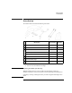
User's Guide Installation • Connecting the selector to the 4155/4156 Turn off the 4155/4156 and 41501 before connecting the instruments. Then connect as shown below. 4155/4156 16442A Test Fixture 4 2 41501 16440A Selector 3 1 16440A Terminal Cable To SMU/Pulse Generator Selector Interface CONTROL Input 3.0 m or 1.5 m Control Cable PGU Input PGU a 3.0 m or 1.5 m Coaxial Cable MPSMU or HPSMU Input SMU 3.0 m or 1.
User's Guide Maintenance Maintenance This section provides the following maintenance information: • Cleaning • Servicing Cleaning the Selector To maintain high performance, the selector must be kept clean. Oil, perspiration, hair, dust, and dirt will degrade the board insulation, which increases leakage current and decreases measurement accuracy. Agilent Technologies recommend the following cleaning procedure: 1. Make sure that voltage or current is not present at any channel. 2.
User's Guide Maintenance Circuit Block Diagram Agilent 16440A User’s Guide, Edition 4 17
User's Guide Maintenance Replaceable Parts When soldering, use low hydrochloric acid solder (Agilent part number: 8090-0433) to prevent the flux in the solder from spreading unnecessarily, and make sure that adjacent terminals are not bridged. After soldering, make sure that there are no lint bridges, which would increase the leakage current. Reference Designation Agilent Part Number Description R1 0757-0442 Resistor 10 kW, 1%, 0.125 W R6 0698-3440 Resistor 196 W, 1%, 0.
User's Guide Maintenance Reference Designation Agilent Part Number Description R13 0698-0085 Resistor 2.61 kW, 1% R15 0757-0279 Resistor 3.
User's Guide Specifications Specifications The "supplemental information" and "typical" entries, in the following specifications are not warranted, but provide useful information about the functions and performance of the instruments. The following specifications data is specified at 23 ± 5 °C and 50 % relative humidity. • Function Agilent 16440A switches either a SMU or PGU to the associated output port. You can expand to 4 channels by adding an additional 16440A.
User's Guide Specifications • Accessories (furnished). See Section 1 for details. • • • • Option 001 • 1.5 m control cable (Agilent part number 04155-61612) • 40 cm triaxial cable (Agilent part number 04155-61605) Option 002 • 3.
User's Guide Specifications Supplemental Information The following reference data is specified at 23 ± 5 °C (73 ± 9 °F) and 50 % relative humidity. • • SMU channel Leakage current less than 100 fA at 100 V Residual resistance 0.2 W typical Stray capacitance (force common) 0.3 pF typical at 1 MHz Stray capacitance (force guard) 15 pF typical at 1 MHz Stray capacitance (guard common) 130 pF typical at 1 MHz PGU channel Residual resistance 3.