Agilent Technologies 8360 L-Series Swept CW Generator (Including Option 001, 004, and 008) User’s Guide Serial Number Prefixes: This manual applies to any swept CW generator with the model and serial number prefix combination shown below. You may have to modfiy this manual so that it applies directly to your instrument version. Refer to the “Instrument History” chapter. Agilent Technologies 83623L/30L 3844A and Below Agilent Technologies 83640L/50L 4040A and Below Part No.
Notice Restricted Rights Legend The information contained in this document is subject to change without notice. Agilent Technologies makes no warranty of any kind with regard to this material, including but not limited to, the implied warranties of merchantability and tness for a particular purpose. Agilent Technologies shall not be liable for errors contained herein or for incidental or consequential damages in connection with the furnishing, performance, or use of this material.
Certification Warranty Agilent Technologies certi es that this product met its published speci cations at the time of shipment from the factory. Agilent Technologies further certi es that its calibration measurements are traceable to the United States National Institute of Standards and Technology, to the extent allowed by the Institute's calibration facility, and to the calibration facilities of other International Standards Organization members.
Assistance Safety Notes iv Product maintenance agreements and other customer assistance agreements are available for Agilent Technologies products. For any assistance, contact your nearest Agilent Technologies Sales and Service O ce. The following safety notes are used throughout this manual. Familiarize yourself with each of the notes and its meaning before operating this instrument. WARNING Warning denotes a hazard.
General Safety Considerations WARNING No operator serviceable parts inside. Refer servicing to qualified personnel. To prevent electrical shock, do not remove covers. For continued protection against fire hazard replace line fuse only with same type and rating (F 5A/250V). The use of other fuses or material is prohibited. This is a Safety Class I product (provided with a protective earthing ground incorporated in the power cord).
CAUTION Note vi Before switching on this instrument, make sure that the line voltage selector switch is set to the voltage of the power supply and the correct fuse is installed. Always use the three-prong ac power cord supplied with this instrument. Failure to ensure adequate earth grounding by not using this cord may cause instrument damage. Before switching on this product, make sure that the line voltage selector switch is set to the voltage of the power supply and the correct fuse is installed.
PREFACE Instruments Covered By This Manual This manual provides user information for the 8360 L-Series Swept CW Generator. This manual applies to instruments having a serial number pre x listed on the title page (behind the \Documentation Map" tab). Some changes may have to be made to this manual so that it applies directly to each instrument; refer to Chapter 5, \Instrument History", to see what changes may apply to your instrument.
Organization Tabs divide the major chapters of this manual. The contents of each chapter is listed in the Table of Contents. HP/Agilent 8360 Documentation Map User's Guide L-Series Documentation For a pictorial representation of the 8360 L-Series documentation, see the \Documentation Map" at the front of this manual. Ordering Manuals A manual part number is listed on the title page of this manual. You may use it to order extra copies of this manual.
Manufacturer's Declaration Note This is to certify that this product meets the radio frequency interference requirements of Directive FTZ 1046/1984. The German Bundespost has been noti ed that this equipment was put into circulation and has been granted the right to check the product type for compliance with these requirements.
Declaration of Conformity x
Compliance with German Noise Requirements This is to declare that this instrument is in conformance with the German Regulation on Noise Declaration for Machines (Laermangabe nach der Maschinenlaermrerordnung 03.GSGV Deutschland). Acoustic Noise Emmission/Geraeuschemission Instrument Markings L LpA <70 dB LpA <70 dB Operator position am Arbeitsplatz Normal position normaler Betrieb per IS) 7779 nach DIN 45635 t.19 The instruction documentation symbol.
Table 0-1. Agilent Technologies Sales and Service Offices UNITED STATES Instrument Support Center Agilent Technologies (800) 403-0801 Headquarters Agilent Technologies S.A. 150, Route du Nant-d'Avril 1217 Meyrin 2/Geneva Switzerland (41 22) 780.
Contents 1. Getting Started What Is In This Chapter . . . . . . . . . . . . How To Use This Chapter . . . . . . . . . . . . Equipment Used In Examples . . . . . . . . . Introducing the Agilent 8360 L-Series Swept CW Generators . . . . . . . . . . . . . . . . . Display Area . . . . . . . . . . . . . . . . . . Entry Area . . . . . . . . . . . . . . . . . . CW Operation and Start/Stop Frequency Sweep . . CW Operation . . . . . . . . . . . . . . . . Start/Stop Frequency Sweep . . . . . . . . . .
Using the Tracking Feature . . . . . . Peaking . . . . . . . . . . . . . . Tracking . . . . . . . . . . . . . ALC Bandwidth Selection . . . . . . . . Using Step Sweep . . . . . . . . . . . Creating and Using a Frequency List . . . Using the Security Features . . . . . . . Changing the Preset Parameters . . . . . Getting Started Programming . . . . . . GPIB General Information . . . . . . . Interconnecting Cables . . . . . . . . Instrument Addresses . . . . . . . . . GPIB Instrument Nomenclature . . . .
Boolean Parameters . . . . . . . . . . . Reading Instrument Errors . . . . . . . . . . Example Programs . . . . . . . . . . . . . . Example Program . . . . . . . . . . . . . Description . . . . . . . . . . . . . . . Program Listing . . . . . . . . . . . . . Program Comments . . . . . . . . . . . Details of Commands and Responses . . . . . . . In This Subsection . . . . . . . . . . . . . . Program Message Syntax . . . . . . . . . . . Subsystem Command Syntax . . . . . . . . Common Command Syntax . . . . . .
An Example Sequence . . . . . . . . . . . Programming the Trigger System . . . . . . . . . In This Subsection . . . . . . . . . . . . . . Generalized Trigger Model . . . . . . . . . . . Overview . . . . . . . . . . . . . . . . . Details of Trigger States . . . . . . . . . . . Inside the Idle State . . . . . . . . . . . Inside the Initiate State . . . . . . . . . . Inside Event Detection States . . . . . . . Inside the Sequence Operation State . . . . Common Trigger Con gurations . . . . . . . .
B. C. NNNNNNNNNNNNNNNNNNNNNNNNNNNNNNNN Blank Disp . . . . . . . . . . . . . . . . . . . . . . . . . . . CONNECTORS . 4 5 . . . . . Copy List . . . . . . . . . . . CorPair Disable . Coupling Factor . 4 5 . . . . . . . CW/CF Coupled . . . . . . . . . . . . . . . . . . . . . . . . . . . . . . . . . . . . . . . . . . . . . . . . . . . . . . . . . . . . . . . . . . . . . . . . . . . . . . . . . . . . . . . . . . . . . . . . . . . . . . . . . . . . . . . . . . . . . . . . . . . . . . . . . . . . .
F. Fault Menu . Fault Info 1 Fault Info 2 Fault Info 3 Fltness Menu . . . . . . . . . . 5 . 4 Freq Cal Menu . Freq Follow . . FREQUENCY 4 Freq Mult . . . Freq Offset . . FullUsr Cal . . . . . . . . . . . . . . . . . . . . . . . . . . . . . . . . . . . . . . . . . . . . . . . . . . . . . . . . . . . . . . . . . . . . . . . . . . . . . . . . . . . . . . . . . . . . . . . . . . . . . . . . . . . . . . . . . . . . . . . . . . . . . . . . . . . . . . . . . . . . . . . . . . . . . . . . . . . . . .
M. . . . . . . . . . . . . . . . . . . . . . . . . . . . . . . . . . . . . . . . . . . . . . . . . . . . . . . . . . . . . . . . . . . . . . . . . . . . . . . . . . . . . . . . . . . . . . . . . . . . . . . . . . . . . . . . . . . . . . . . . . . . . . . . . . . . . . . . . . . . . . . . . . . . . . . . . . . . . . . . . . . . . . . . . . . . . . . . . . . . . . . . . . . . . . . . . . . . . . . . . . . . . . . . . . . . . . . . . . . . . . . . . . . . . . . . . . . . . . . . . . . . . . . .
R. . . . . Ref Osc Menu . 4 5 . . ROTARY KNOB . . . . . . . . . . . . . . . . . . . . . . . . . . . . . . . . . . . . . . . . . . . . . . . . R-1 R-1 R-2 R-2 . . . . . . . . . . . . . . . . . Save Lock . . . . . . . . . . . . . . Save User Preset . . . . . . . . . . SCPI Conformance Information . . . . . SCPI COMMAND SUMMARY . . . . . SCPI STATUS REGISTER STRUCTURE Security Menu . . . . . . . . . . . . Selftest (Full) . . . . . . . . . . . Set Atten . . . . . . . . . . . . . . 4 5 . . . . . .
T. . . . . . . . . . . . . . . . . . . . . . . . . . . . . . . . . . . . . . . . . . . . . . . . . . . . . . . . . . . . . . . . . . . . . . . T-1 T-1 T-2 T-2 T-3 T-3 . . . . . . . . . . . . . . . . . . . . . . . . . . . . . . . . . . . . . . . . . . . . . . . . . . . . . . . . . . . . . . . . . . . . . . . . . . . . . . . . . . . . . . . . . . . . . . . . . . . U-1 U-1 U-2 U-2 U-3 U-4 U-4 U-5 U-5 . . . . . . . . . . . . . . . . . . . . . . . . . . . . . . . . . . . .
2c. Speci cations Frequency . . . . . . . . . . . . . . . . . . . Range . . . . . . . . . . . . . . . . . . . . Resolution . . . . . . . . . . . . . . . . . . Frequency Bands (for CW signals) . . . . . . . Frequency Modes: . . . . . . . . . . . . . . CW and Manual Sweep . . . . . . . . . . . . Synthesized Step Sweep . . . . . . . . . . . . Synthesized List Mode . . . . . . . . . . . . Ramp Sweep Mode . . . . . . . . . . . . . . Internal 10 MHz Time Base . . . . . . . . . . RF Output . . . . . . . . . . . .
Option 910 Extra Operating & Service Guides . 2c-13 Option 013 Rack Flange Kit . . . . . . . . . 2c-13 Option W30 Two Years Additional Return{To{HP Service . . . . . . . . . . . . . . . . . 2c-13 3. Installation Initial Inspection . . . . . . . . . . . . . . . . Equipment Supplied . . . . . . . . . . . . . . Options Available . . . . . . . . . . . . . . . Preparation for Use . . . . . . . . . . . . . . . Power Requirements . . . . . . . . . . . . . Line Voltage and Fuse Selection . . . . . . . .
The HP/Agilent 83550 Series Millimeter-wave Source Modules . . . . . . . . . . . . The HP/Agilent 8970B Noise Figure Meter . Remote Operation . . . . . . . . . . . . . Language Compatibility . . . . . . . . . . Network Analyzer Language . . . . . . . . Test and Measurement System Language . . Control Interface Intermediate Language . . Converting from Network Analyzer Language to SCPI . . . . . . . . . . . . . . . . . Numeric Su xes . . . . . . . . . . . . . Status Bytes . . . . . . . . . . . . . . . 4.
Figures 0-1. Typical Serial Number Label . . . . . . . . . . 1-1. The 8360 L-Series Swept CW Generator . . . . . 1-2. Display . . . . . . . . . . . . . . . . . . . 1-3. Entry Area . . . . . . . . . . . . . . . . . 1-4. CW Operation and Start/Stop Frequency Sweep . 1-5. Center Frequency and Span Operation . . . . . 1-6. Power Level and Sweep Time Operation . . . . . 1-7. Continuous, Single, and Manual Sweep Operation 1-8. Marker Operation . . . . . . . . . . . . . . 1-9.
1-37. Inside the Initiate State . . . . . . . . . . . . 1-38. Inside an Event Detection State . . . . . . . . 1-39. Inside the Sequence Operation State . . . . . . 1-40. The INIT Trigger Con guration . . . . . . . . 1-41. The TRIG Trigger Con guration . . . . . . . . 1-42. 8360 Simpli ed Trigger Model . . . . . . . . . A-1. ALC System Simpli ed Block Diagram . . . . . A-2. Typical External Leveling Hookup . . . . . . . C-1. Auxiliary Interface Connector . . . . . . . . . C-2. GPIB Connector and Cable . . .
Tables 1-1. Keys Under Discussion in This Section . . . . . 1-2. SWEep Command Table . . . . . . . . . . . 1-3. SCPI Data Types . . . . . . . . . . . . . . 1-4. Sample Swept CW Generator Commands . . . . C-1. Pin Description of the Auxiliary Interface . . . . D-1. Mnemonics used to Indicate Status . . . . . . . S-1. 8360 SCPI COMMAND SUMMARY . . . . . . 3-1. Adapter Descriptions and Part Numbers Shipped with Each Swept CW Generator Model . . . 3-2. Language GPIB Addresses . . . . . . . . . . . 3-3.
1 Getting Started What Is In This Chapter This chapter contains information on how to use the Agilent 8360 L-Series Swept CW Generator. The information is separated into three sections. Basic For the novice user unfamiliar with the 8360 L-Series Swept CW Generator. This section describes the basic features of the swept CW generator. Advanced For the user familiar with swept CW generators, but not necessarily familiar with how to use the special features of the 8360 L-Series Swept CW Generator.
How To Use This Chapter Equipment Used In Examples To use this chapter e ectively, refer to the tabbed section \Menu Maps". Menu maps can be folded out to be viewed at the same time as the Getting Started information, as illustrated. The following table lists the equipment used in the operation examples shown in this chapter. You can substitute equipment, but be aware that you may get di erent results than those shown.
Getting Started Basic Introducing the Agilent 8360 The 8360 L-Series Swept CW Generators are high performance, broadband frequency swept CW generators. L-Series Swept CW Generators Figure 1-1. The 8360 L-Series Swept CW Generator initializes the front panel settings and runs the swept CW generator through a brief self-test. In the following examples, unless 5.
Display Area Figure 1-2. Display This area typically displays the frequency and power information of the current instrument state. When data entry is expected, the swept CW generator uses all or part of this area to record the entries. The active entry arrow (-->) indicates the active entry function and its current value. Message Line: This line is used to display: ALC level status. Unlock information. Timebase status. RF output status.
Entry Area All function values are changed via the rotary knob and/or keys of the entry area. Figure 1-3. Entry Area The following are active only when the swept CW generator expects an input. 4 5: This key lets you turn o or on the active entry area. Turning o the entry area after a value is entered prevents accidental changes. ENTRY ON LED: This LED lights when the entry area is active. Arrow Keys: The up/down arrow keys let you increase or decrease a numeric value.
CW Operation and Start/Stop Frequency Sweep CW Operation CW operation is one of the major functions of the swept CW generator, and is easy to do using front panel keys. In CW operation, the swept CW generator produces a single, low-noise, synthesized frequency. Try this example: Press 4 5 4 5 4 5 4 5 4 5 4 5 4 5 4 5 4 5 4 5 4 5. Check the active entry area. It indicates: CW 1 2 . 3 4 5 6 7 8 GHz --> CW: 12345.
Figure 1-4. CW Operation and Start/Stop Frequency Sweep CW Operation Start/Stop Frequency Sweep 1. Press 4CW5. 2. Enter value. 3. Press terminator key. 1. 2. 3. 4. 5. 6. Press 4START5. Enter value. Press terminator key. Press 4STOP5. Enter value. Press terminator key.
Center Frequency/Span Operation Center frequency/span is another way of establishing swept operation. This is just a di erent way of de ning sweep limits. As an example of center frequency/span operation: Press 4 5 45 4 5. Press 4 5 4 5 4 5. The swept CW generator is now sweeping from 3.5 to 4.5 GHz (to view these gures, press either 4 5 or 4 5, then 4 5). The data display area indicates the center frequency, as well as, the span. Notice that the green SWEEP LED is on.
Figure 1-5. Center Frequency and Span Operation Center Frequency Operation Span Operation 1. Press 4CENTER5. 2. Enter value. 3. Press terminator key. 1. Press 4SPAN5. 2. Enter value. 3. Press terminator key.
Power Level and Sweep Time Operation Power Level Operation The swept CW generator can produce leveled power for CW, swept frequency, or power sweep operation. The selected power level can range from 020 dBm (0110 dBm for Option 001 swept CW generators) to +25 dBm. 5 405 4 5 4 5 4 5. The active entry For practice: Press 4 area shows: 2 POWER LEVEL --> POWER LEVEL: 020.
Figure 1-6. Power Level and Sweep Time Operation Power Level Operation Sweep Time Operation 1. Press 4POWER LEVEL5. 2. Enter value. 3. Press 4dB(m)5. 1. Press 4SWEEP TIME5. 2. Enter value. 3. Press terminator key.
Continuous, Single, and Manual Sweep Operation Continuous sweep is the operation mode set when the swept CW generator is preset. It simply means that when the swept CW generator is performing a swept operation, the sweeps will continuously sweep-retrace-sweep-retrace until a di erent sweep mode is selected. To choose this sweep mode, press 4 5. To change from continuous sweep to single sweep operation, press 4 5.
Figure 1-7. Continuous, Single, and Manual Sweep Operation Single Sweep Continuous Sweep Manual Sweep 1. Press 4SINGLE5. 1. Press 4CONT5. 1. Press SWEEP 4MENU5. 2. Press Manual Sweep . 3. Use the rotary knob to adjust frequency.
Marker Operation The swept CW generator has ve frequency markers that can be used as xed frequency \landmarks," or as variable frequency pointers on a CRT display. To view the marker features of the swept CW generator on a CRT, connect the swept CW generator as shown in Figure 1-8. Refer to menu map 3, MARKER. Press 4 5. Press 4 5 4 5 4 5. Press 4 5 4 5 4 5. Press 4 5. Select Marker M1 and enter 4 5 4 5. The swept CW generator is sweeping from 3 to 7 GHz, with a 100 ms sweep speed.
Marker 1 was chosen because it is selected as the delta marker reference. To change reference markers, select Delta Mkr Ref . Select M2 as the reference. Watch the display change to indicate: NNNNNNNNNNNNNNNNNNNNNNNNNNNNNNNNNNNNNNNNN NNNNNNNN --> DELTA MKR (3-2) : 1200.
Saving and Recalling an Instrument State The save/recall registers store and access a previously set instrument state. For example, set the swept CW generator to sweep from 3 to 15 GHz at a 010 dB power level, with markers 1 and 2 set at 4.5 and 11.2 GHz. Press 4 5 4 5 4 5. Press 4 5 4 5 4 5 4 5. 5 405 4 5 4 5 4 5. Press 4 Press 4 5. Select Marker M1 4 5 4 5 4 5 4 5. Select Marker M2 4 5 4 5 4 5 4 5 4 5. To save this instrument state in register 1, press 4 5 4 5.
Figure 1-9. Saving and Recalling an Instrument State Save Recall 1. Set up swept CW generator as desired. 2. Press 4SAVE5. 3. Press a number 1 through 8. 1. Press 4RECALL5. 2. Press a number 0 through 8.
Power Sweep and Power Slope Operation Power Sweep Operation The power sweep function allows the power output to be swept (positive or negative) when the swept CW generator is in the CW frequency mode. The power output of the swept CW generator determines the maximum leveled power sweep that can be accomplished. For this example, refer to the \Menu Map" section. Zero and calibrate the power meter. Connect the instruments as shown in Figure 1-10. Press 4 5 4 5 4 5. 5 45 4 5. Press 4 Press 4 5 45 4 5 4 5.
Select Power Sweep (asterisk on). Press 4 5. The swept CW generator performs a power sweep beginning at 020 dBm and ending at +5 dBm. The power meter indicates +25 dB. NNNNNNNNNNNNNNNNNNNNNNNNNNNNNNNNNNN SINGLE Power Slope Operation This function allows for compensation of high frequency system or cable losses by linearly increasing the power output as the frequency increases. For this example, refer to the \Menu Map" section. Press Power Slope , the active entry area displays: --> RF SLOPE: X.
Advanced Getting Started Advanced This section of Chapter 1 describes the use of many of the unique features of the 8360 L-Series Swept CW Generators. The format used is similar to the one used on the previous pages. When referred to a menu map number, go to the Menu Map tab and unfold the menu map so that you can view it together with the text. Some menus have more than one page of softkeys. Select the more m/n softkey to view the next page of softkeys.
Advanced Table 1-1.
Externally Leveling the Swept CW Generator Leveling with Detectors/Couplers /Splitters In externally leveled operations, the output power from the swept CW generator is detected by an external sensor. The output of this detector is returned to the leveling circuitry, and the output power is automatically adjusted to keep power constant at the point of detection. Figure 1-11 illustrates a typical setup for external leveling.
To level externally: 1. Set up the equipment as shown. For this example, the detector/coupler setup is used. 2. Refer to menu map 1. 3. Press 4 5. 4. Select Leveling Point ExtDet . 5. Set the coupling factor. Select Coupling Factor 405 4 5 4 5 4 5. Power splitters have a coupling factor of 0 dB.
Figure 1-12.
External Leveling Used With the Optional Step Attenuator Some external leveling applications require low output power from the swept CW generator. The swept CW generator automatically uncouples the attenuator from the ALC system for all external leveling points. Press 4 5. Note the display. It shows: POWER LEVEL --> ATTEN 0 dB, POWER LEVEL: 0.
Leveling with Power Meters Leveling with a power meter is similar to leveling with a diode detector. Figure 1-13 shows the setup for power meter leveling. Figure 1-13. Leveling with a Power Meter 1. 2. 3. 4. 5. Set up the equipment as shown. Be sure to set the power meter to manual range mode and note the range. Refer to menu map 1. Press 4 5. Select Leveling Point PwrMtr . Select Pwr Mtr Range . Enter the range value set for the power meter as noted in step 1. 6. Select Coupling Factor , press 4 5 4 5.
Leveling with MM-wave Source Modules Millimeter-wave source module leveling is similar to power meter leveling. The following gures illustrate the setups for leveling with a mm-wave source module. Figure 1-14. MM-wave Source Module Leveling High power model swept CW generators can externally level mm-wave source modules to maximum speci ed power without a microwave ampli er.
Figure 1-15. MM-wave Source Module Leveling Using a Microwave Amplifier 1. 2. 3. 4. 5. Hint Set up the equipment as shown. Refer to menu map 1. Select Leveling Point Module . Select Module Menu . Select Module Select Auto or Front or Rear , depending on where the interface connection is made. All of the ALC data necessary to communicate properly with the swept CW generator is exchanged via the SOURCE MODULE INTERFACE.
Working with Mixers/Reverse Power Effects Note Uncoupled operation applies to Option 001 swept CW generators only. Uncoupled operation is useful when working with mixers. Figure 1-16 shows a hypothetical setup where the swept CW generator is providing a small signal to a mixer. The swept CW generator output is 08 dBm, which in Leveling Mode Normal results in ATTEN = 0 dB, ALC Level = 08 dBm. The mixer is driven with an LO of +10 dBm, and has LO to RF isolation of 15 dB.
Figure 1-16. Reverse Power Effects, Coupled Operation with 08dBm Output Figure 1-17.
Working with Spectrum Analyzers/Reverse Power Effects Reverse power is a problem with spectrum analyzers that do not have preselection capability. Some analyzers have as much as +5 dBm LO feedthrough coming out of their RF input, at some frequencies. The e ects of reverse power are less in the heterodyne band (0.01 to 2.0 GHz) where the power ampli er provides some broadband matching. Similarly, at frequencies above 2.
Optimizing Swept CW Generator Performance Creating and Applying the User Flatness Correction Array The following examples demonstrate the user atness correction feature: 1. Using an HP/Agilent 437B power meter to automatically enter correction data for a swept 4 to 10 GHz measurement. 2. Manually entering correction data for a stepped (List Mode) measurement. 3. Making swept mm-wave measurements, automatically entering correction data for an arbitrary list of correction frequencies. 4.
Creating a User Flatness Array Automatically, Example 1 In this example, a atness array containing correction frequencies from 4 to 10 GHz at 1 GHz intervals is created. An HP/Agilent 437B power meter controlled by the swept CW generator through the interface bus is used to enter the correction data into the atness array. For this example, refer to menu map 5, POWER. 1.
Note No other devices can be connected to the GPIB cable. Set up Swept CW Generator Parameters 6. On the swept CW generator, press 4 7. FREQUENCY 4 5 4 5 4 5, 4 5 45 4 5. 8. 4 . PRESET5 START POWER LEVEL 0 4 STOP5 GHz . 415 405 4GHz5 dB(m) Access User Flatness Correction Menu 9. Press POWER 4 5. Select Fltness Menu . 10. Select Delete Menu Delete All . This step insures that the atness array is empty. 11. Press 4 5. Leave the delete menu and return to the previous softkey menu. 12.
Creating a User Flatness Array, Example 2 This example shows how to use the swept CW generator and a power meter in manual entry mode. This example also introduces two features of the swept CW generator. The softkey Freq Follow simpli es the data entry process and the softkey List Mode sets up a list of arbitrary test frequencies. The frequency follow feature automatically sets the source to a CW test frequency equivalent to the active correction frequency in the user atness correction table.
Figure 1-19. Creating a User Flatness Array For this example, refer to menu map 5, POWER. 1. The equipment setup shown in Figure 1-19 assumes that if your setup has an external leveling con guration, the steps necessary to correctly level have been followed. If you have questions about external leveling, refer to \Externally Leveling the Swept CW Generator". Set up Power Meter 2. Zero and calibrate the power meter/sensor. 3. Connect the power sensor to the point where atness corrected power is desired.
Access User Flatness Correction Menu 9. Press POWER 4 5. Select Fltness Menu . 10. Select Delete Menu Delete All . This step insures that the atness array is empty. 11. Press 4 5. Leave the delete menu and return to the previous softkey menu. 12. Select Copy List This step copies the frequency list into the correction table in sequential order. 13. Select Freq Follow . This sets the swept CW generator to CW frequency mode to facilitate taking correction information.
Swept mm-wave Measurement with Arbitrary Correction Frequencies, Example 3 Note The focus of this example is to use user atness correction to obtain at power at the output of the HP/Agilent 83550 series mm-wave source modules. In this case we will use non-sequential correction frequencies in a swept 26.5 to 40 GHz measurement with an HP/Agilent 83554 source module.
Figure 1-20. Creating Arbitrarily Spaced Frequency-Correction Pairs in a Swept mm-wave Environment For this example, refer to menu map 5, POWER. 1. The equipment setup shown in Figure 1-20 assumes that you have followed the steps necessary to correctly level the con guration. If you have questions about external leveling, refer to \Externally Leveling the Swept CW Generator". Set up Power Meter 2. Zero and calibrate the power meter/sensor. 3. Connect the power sensor to test port. 4.
Note U, V, and W-band power sensors are not available from Agilent. For these frequencies use the Anritsu ML83A Power Meter with the MP715-004 (40 to 60 GHz), the MP716A (50 to 75 GHz), or the MP81B (75 to 110 GHz) power sensors. Since the Anritsu model ML83A Power Meter is not capable of internally storing power sensor cal factors, you must manually correct the data entry. Refer to example 2 for information on manual entry of correction data. Set up Swept CW Generator Parameters 5. 5.
generator is using (address 13 is assumed). Refer to the menu map 8, System, for the key sequence necessary to reach softkey Meter Adrs . NNNNNNNNNNNNNNNNNNNNNNNNNNNNNNNN Enable User Flatness Correction 13. When the operation is complete, (a message is displayed) the atness correction array is ready to be applied to your setup. 14. To save the swept CW generator parameters including the correction table in an internal register, press 4 5 4 5 (n = number 1 through 8). 5 15.
Scalar Analysis Measurement with User Flatness Corrections, Example 4 Note The following example demonstrates how to set up a scalar analysis measurement (using an HP/Agilent 8757 Scalar Network Analyzer) of a 2 to 20 GHz test device such as, an ampli er. User atness correction is used to compensate for power variations at the test port of a directional bridge. Follow the instructions to set up the swept CW generator, then con gure the system as shown in Figure 1-21.
Example Overview Note In this example, you use an HP/Agilent 437B power meter to automatically enter correction data into the array. It is necessary to turn o the HP/Agilent 8757 System Interface (controlled from the front-panel of the analyzer) so that the swept CW generator can temporarily control the power meter over GPIB. When the correction data entry process is complete, enable user atness correction and set the desired test port power level.
6. Turn o the HP/Agilent 8757 System Interface. Use the analyzer SYSINTF ON OFF softkey found under the SYSTEM menu to deactivate the system interface. NNNNNNNNNNNNNNNNNNNNNNNNNNNNNNNNNNNNNNNNNNNN Access User Flatness Correction Menu 7. On the swept CW generator, press POWER 4 5. Select Fltness Menu . 8. Select Delete Menu Delete All . This step insures that the atness array is empty. 9. Press 4 5. Leave the delete menu and return to the previous softkey menu. 10. Select Auto Fill Start 4 5 4 5.
Enable User Flatness Correction 17. When the operation is complete, (a message is displayed) the atness correction array is ready to be applied to your setup. 18. Disconnect the power meter/sensor. 5 45 4 5. 19. On the swept CW generator, press 4 Where n = Po max 0 Ppath loss for maximum leveled power at the test port. 20. To save the swept CW generator parameters including the correction table in an internal register, press 4 5 4 5 (n = number 1 through 8).
Using Detector Calibration Detector calibration is useful for characterizing and compensating for negative diode detectors used in external leveling. Detectors may be characterized by three operating regions as shown in Figure 1-12: the square law, the linear, and the transition region. The following steps use an HP/Agilent 437B to automatically characterize the operating regions and use this information to automatically compensate for the detector being used.
map 8, System, for the key sequence necessary to reach softkey Meter Adrs . 9. When the operation is complete, (a message is displayed) disconnect the power meter/sensor. The swept CW generator has stored the compensation information in its memory and is using it to calibrate the detector's output voltage relative to power.
Using the Tracking Feature Peaking Peaking is the function that aligns the output lter (YTM) so that its passband is centered on the RF output, in CW or manual-sweep mode. Use peaking to obtain the maximum available power and spectral purity, and best pulse envelopes, at any given frequency above 2.0 GHz. The YTM is inactive for the low band frequencies (10 MHz to 2.0 GHz). To peak at the present CW frequency: Press 4 5. Select Tracking Menu Peak RF Once .
ALC Bandwidth Selection The ALC bandwidth defaults at factory preset to the auto selection ALC Bandwidth Select Auto which selects the appropriate bandwidth (high or low) for each application. To make the bandwidth selection, the swept CW generator determines which functions are activated and uses the decision tree shown in Figure 1-23. NNNNNNNNNNNNNNNNNNNNNNNNNNNNNNNNNNNNNNNNNNNNNNNNNNNNNNNNNNNNNNNNNNNNNNNNNNNNN Figure 1-23.
Using Step Sweep 1. 2. 3. 4. 5. 6. Refer to menu map 2. Press FREQUENCY 4 5. Select Step Swp Menu . Select Step Size . Enter the desired increment value. Select Step Points . Enter the number of points desired. Determine the dwell time desired, select Step Dwell and enter a value, or choose the dwell time determined by the ramp mode sweep time, select Dwell Coupled . 7. Determine the triggering scheme, select Step Swp Pt Trig Auto , Bus , or Ext . 8. Press SWEEP 4 5. 9.
Creating and Using a Frequency List 1. Refer to menu map 2. 2. Press FREQUENCY 4 5. 3. Select List Menu . To use the frequency points of a frequency list to create the frequency portion of the user atness correction array: 1. Refer to menu map 5. 2. Press POWER 4 5. 3. Select Fltness Menu . 4. Select Copy List .
Using the Security Features To access the security menu: 1. Refer to menu map 8. 2. Press SYSTEM 4 5. 3. Select Security Menu .
Changing the Preset Parameters 1. Set up the swept CW generator in the desired operation state to be used as the preset state. 2. Refer to menu map 8. 3. Press SYSTEM 4 5. 4. Select Save User Preset . 5. Select Preset Mode User . Whenever the 4 5 key is pressed, the swept CW generator will return to the operation state setup and saved in steps 1 and 4.
Programming GPIB, the General Purpose Interface Bus, is the instrument-toinstrument communication system between the swept CW generator Programming and up to 14 other instruments. Any instrument having GPIB capability can be interfaced to the swept CW generator, including non-HP instruments that have \GPIB," \IEEE-488," \ANSI MC1.1," or \IEC-625" capability (these are common generic terms for GPIB; all are electrically equivalent although IEC-625 uses a unique connector).
GPIB General Information Interconnecting Cables Figure C-2 shows the swept CW generator rear-panel GPIB connector and suitable cables, and describes the procedures and limitations for interconnecting instruments. Cable length restrictions, also described in Figure C-2, must be observed. Instrument Addresses Each instrument in an GPIB network must have a unique address, ranging in value from 00-30 (decimal).
In the programming explanations that follow, speci c examples are included that are written in a generic dialect of the BASIC language. BASIC was selected because the majority of GPIB computers have BASIC language capability. However, other languages can also be used.
Remote Remote causes an instrument to change from local control to remote control. In remote control, the front panel keys are disabled (except for the 4 5 key and the POWER switch), and the amber REMOTE annunciator is lighted. The syntax is: LOCAL where the device selector is the address of the instrument appended to the GPIB port number. Typically, the GPIB port number is 7, and the default address for the swept CW generator is 19, so the device selector is 719.
Local Local is the complement to REMOTE, causing an instrument to return to local control with a fully enabled front panel. The syntax is: Some BASIC examples: 10 LOCAL 7 10 LOCAL 719 which e ects all instruments in the network, or for an addressed instrument (address 19). Related statements used by some computers: RESUME Clear Clear causes all GPIB instruments, or addressed instruments, to assume a \cleared" condition, with the de nition of \cleared" being unique for each device.
Some BASIC examples: 10 CLEAR 7 10 CLEAR 719 to clear all GPIB instruments, or to clear an addressed instrument. Related statements used by some computers: RESET CONTROL SEND The preceding statements are primarily management commands that do not incorporate programming codes. The following two statements do incorporate programming codes, and are used for data communication. Output Output is used to send function commands and data commands from the controller to the addressed instrument.
A BASIC example: 100 OUTPUT 719; "programming codes" The many programming codes for the swept CW generator are listed in the \SCPI Command Summary" in Chapter 2. Related statements used by some computers: CONTROL CONVERT IMAGE IOBUFFER TRANSFER Enter Enter is the complement of OUTPUT, and is used to transfer data from the addressed instrument to the controller. The syntax is: ENTER is always used in conjunction with OUTPUT, such as: 100 OUTPUT 719; " . .. programming codes . .. " 110 ENTER 719; " . . .
Note Be careful when using byte-counting image speci ers. If the requested number of bytes does not match the actual number available, data might be lost, or the program might enter an endless wait state. The suppression of the EOL sequence is frequently necessary to prevent a premature termination of the data input. When not speci ed, the typical EOL termination occurs when an ASCII LF (line feed) is received.
Getting Started with SCPI Definitions of Terms This section of Chapter 1 describes the use of the Standard Commands for Programmable Instruments language (SCPI). This section explains how to use SCPI commands in general. The instrument command summary (at the end of this chapter) lists the speci c commands available in your instrument. This section presents only the basics of SCPI. If you want to explore the topic in greater depth, see the paragraph titled, \Related Documents.
Standard Notation This section uses several forms of notation that have speci c meaning. Command Mnemonics Many commands have both a long and a short form, and you must use either one or the other (SCPI does not accept a combination of the two). Consider the FREQuency command, for example. The short form is FREQ and the long form is FREQUENCY (this notation style is a shorthand to document both the long and short form of commands).
Commands and Responses," discusses message terminators in more detail. Response Examples Response examples look like this: 1.23 These are the characters you would read from an instrument after sending a query command. To actually pull them from the instrument into the controller, use the input statement appropriate to your application programming language. If you have problems, study the details of how the input statement operates.
Essentials for Beginners Program and Response Messages This subsection discusses elementary concepts critical to rst-time users of SCPI. Read and understand this subsection before going on to another. This subsection includes the following topics: These paragraphs introduce the Program and Response basic types of messages sent between Messages instruments and controllers. Subsystem Command Trees These paragraphs describe the tree structure used in subsystem commands.
Types of Commands Commands can be separated into two groups, common commands and subsystem commands. Common commands are generally not measurement related. They are used to manage macros, status registers, synchronization, and data storage. Common commands are easy to recognize because they all begin with an asterisk, such as *IDN?, *OPC, and *RST. Common commands are de ned by IEEE 488.2. Subsystem commands include all measurement functions and some general purpose functions.
Subsystem Command Trees The Command Tree Structure Most programming tasks involve subsystem commands. SCPI uses a hierarchical structure for subsystem commands similar to the le systems on most computers. In SCPI, this command structure is called a command tree . Figure 1-25. A Simplified Command Tree In the command tree shown in Figure 1-25, the command closest to the top is the root command , or simply the root . Notice that you must follow a particular path to reach lower level subcommands.
Colon When it is between two command mnemonics, a colon moves the current path down one level in the command tree. For example, the colon in MEAS:VOLT speci es that VOLT is one level below MEAS. When the colon is the rst character of a command, it speci es that the next command mnemonic is a root level command. For example, the colon in :INIT speci es that INIT is a root level command. Semicolon A semicolon separates two commands in the same message without changing the current path.
Figure 1-26. Proper Use of the Colon and Semicolon In Figure 1-26, notice how proper use of the semicolon can save typing.
Subsystem Command Tables These paragraphs introduce a more complete, compact way of documenting subsystems using a tabular format. The command table contains more information than just the command hierarchy shown in a graphical tree. In particular, these tables list command parameters for each command and response data formats for queries. To begin this exploration of command tables, consider a simpli ed SWEep subsystem for the swept CW generator in both the graphical and tabular formats. Figure 1-27.
the matching command. The parameter type is listed adjacent to each named parameter. More About Commands Query and Event Commands. Because you can query any value that you can set, the query form of each command is not shown explicitly in the command tables. For example, the presence of the swept CW generator :SWEep:DWELl command implies that a :SWEep:DWELl? also exists. If you see a table containing a command ending with a question mark, it is a query only command.
Example 1: "FREQuency:CW 5 GHZ; MULTiplier 2" The command is correct and will not cause errors. It is equivalent to sending: "FREQuency:CW 5 GHZ; :FREQuency:MULTiplier 2". Example 2: "FREQuency 5 GHZ; MULTiplier 2" This command results in a command error. The command makes use of the default [:CW] node. When using a default node, there is no change to the current path position. Since there is no command "MULT" at the root, an error results.
Examples of numeric parameters: 100 100. -1.23 4.56e3 -7.89E-01 +256 .5 no decimal point required fractional digits optional leading signs allowed space allowed after e in exponents use either E or e in exponentials leading + allowed digits left of decimal point optional Examples of numeric parameters in commands: 100 OUTPUT @Source;":FREQuency:STARt 1.0E+09" 110 OUTPUT @Source;":LIST:FREQuency 10.
Use discrete parameters to program settings that have a nite number of values. Discrete parameters use mnemonics to represent each valid setting. They have a long and a short form, like command mnemonics. You can use mixed upper and lower case letters for discrete parameters. Examples of discrete parameters: Discrete Parameters.
Reading Instrument Errors When debugging a program, you may want to know if an instrument error has occurred. Some instruments can display error messages on their front panels. If your instrument cannot do this, you can put the following code segment in your program to read and display error messages.
Example Programs The following is an example program using SCPI compatible instruments. The example is written in HP BASIC. This example is a stimulus and response application. It uses a source and counter to test a voltage controlled oscillator. Example Program Description. This example demonstrates how several SCPI instruments work together to perform a stimulus/response measurement. This program measures the linearity of a voltage controlled oscillator (VCO).
210 220 230 240 250 260 270 280 290 300 310 320 330 340 350 360 370 380 390 400 410 420 430 440 450 460 470 480 ! ! ! ! ! OUTPUT @Stimulus;"*IDN?" ENTER @Stimulus;Id$ PRINT Id$ PRINT PRINT "Counter Used ...
a 1 in the source Output Queue. The program waits at line 410 until the 1 returned by *OPC? is entered. Note that following each OUTPUT containing a query is an ENTER to retrieve the queried value. If you do not use paired OUTPUTs and ENTERs, you can overwrite data in the instrument Output Queue and generate instrument errors. 470 to 480: Disconnect output terminals of the instruments from the unit under test, and end the program.
Details of Commands and Responses In This Subsection This subsection describes the syntax of SCPI commands and responses. It provides many examples of the data types used for command parameters and response data. The following topics are explained: Program Message These paragraphs explain how to properly Syntax construct the messages you send from the computer to instruments. Response Message These paragraphs discuss the format of messages sent from instruments to the Syntax computer.
a semicolon. You must always end a program message with one of the three program message terminators shown in Figure 1-29. Use , <^END>, or <^END> as the program message terminator. The word <^END>> means that EOI is asserted on the GPIB interface at the same time the preceding data byte is sent. Most programming languages send these terminators automatically. For example, if you use the HP BASIC OUTPUT statement, is automatically sent after your last data byte.
Figure 1-31. Simplified Common Command Syntax As with subsystem commands, use a to separate a command mnemonic from subsequent parameters. Separate adjacent parameters with a comma. Parameter types are explained later in this subsection. Response Message Syntax Figure 1-32 shows a simpli ed view of response message syntax. Figure 1-32. Simplified Response Message Syntax Response messages can contain both commas and semicolons as separators.
SCPI Data Types These paragraphs explain the data types available for parameters and response data. They list the types available and present examples for each type. SCPI de nes di erent data formats for use in program messages and response messages. It does this to accommodate the principle of forgiving listening and precise talking. Recall that forgiving listening means instruments are exible, accepting commands and parameters in various formats.
rounds the parameter. For example, if an instrument has a programmable output impedance of 50 or 75 ohms, you speci ed 76.1 for output impedance, the value is rounded to 75. If the instrument setting can only assume integer values, it automatically rounds the value to an integer. For example, sending *ESE 10.123 is the same as sending *ESE 10. Examples of numeric parameters: 100 100. -1.23 4.56e3 -7.89E-01 +256 .
Use discrete parameters to program settings that have a nite number of values. Discrete parameters use mnemonics to represent each valid setting. They have a long and a short form, just like command mnemonics. You can used mixed upper and lower case letters for discrete parameters. Discrete Parameters.
response data are decimal representations of integer values including optional signs. Most status register related queries return integer response data. Examples of integer response data: Integer Response Data. Integer 0 +100 -100 256 signs are optional leading + sign allowed leading sign allowed never any decimal point response data are similar to discrete parameters. The main di erence is that discrete response data return only the short form of a particular mnemonic, in all upper case letters.
Programming Typical Measurements In This Subsection This subsection illustrates how the general SCPI concepts presented in previous subsections apply to programming real measurements. To introduce you to programming with SCPI, we must list the commands for the swept CW generator. We will begin with a simpli ed example. Using the Example Programs The example programs are interactive. They require active participation by the operator.
Use of the Command Tables In Table 1-4, notice that a new column titled \Allowed Values" has been added to the command table. This column lists the speci c values or range of values allowed for each parameter. A vertical bar (j) separates values in a list from which you must choose one value. The commands listed in the table are only part of all the available SCPI commands of the swept CW generator. For a complete listing of the programming codes see \SCPI Command Summary" in Chapter 2. Table 1-4.
Table 1-4.
GPIB Check, Example Program 1 This rst program is to verify that the GPIB connections and interface are functional. Connect a controller to the swept CW generator via an GPIB cable. Clear and reset the controller and type in the following program: 10 20 30 40 50 60 70 80 90 Source=719 ABORT 7 LOCAL Source CLEAR Source REMOTE Source CLS PRINT "The source should now be in REMOTE." PRINT "Verify that the 'REMOTE' LED is on.
When the swept CW generator is in REMOTE mode, all the front panel keys are disabled except the LOCAL key. But, when the LOCAL LOCKOUT command is set on the bus, even the LOCAL key is disabled. The LOCAL command, executed from the controller, is then the only way to return all (or selected) instruments to front panel control. Continue example program 1.
9. Attempt to change the start frequency and press 4 5. Verify that this is impossible. 10. Now press the swept CW generator 4 5 key and verify that still no action is taken. 11. Execute a \continue" on the controller. With the controller displaying \LOCAL mode", verify that the swept CW generator REMOTE LED is o . Also verify that all sweep functions now can be modi ed via the front panel controls. Note that the swept CW generator 4 5 key produces the same result as programming LOCAL 719 or LOCAL 7.
Setting Up A Typical Sweep, Example Program 3 In swept operation, the swept CW generator is programmed for the proper sweep frequency range, sweep time, power level, and marker frequencies for a test measurement. This program sets up the swept CW generator for a general purpose situation. The instrument is the same as in program 1.
110: Set the sweeptime to 500 ms. Notice that upper/lower case in commands does not matter. Also spaces before the su x (\MS") are not required in SCPI. 120 and 130: Set markers 1 and 2 to a xed value. Notice that the value for marker 2 does not end with a frequency su x. Hertz is a default terminator and is understood. 140: Wait until the source has completed setting up the commands that have been sent so far before turning on the output.
Queries, Example Program 4 The following example demonstrates the use of query commands and response data formats. Clear and reset the controller and type in the following program: 10 20 30 40 50 60 70 80 90 100 110 120 130 140 150 160 170 180 190 200 210 220 230 240 250 260 270 Source=719 ABORT 7 LOCAL 7 CLEAR Source REMOTE Source CLS OUTPUT Source;"*RST" OUTPUT Source;"POWER:LEVEL -5 dBm;STATE ON" OUTPUT Source;"FREQ:CW?" ENTER Source;F PRINT "Present source CW frequency is : ";F/1.
130: Enter the query response into a variable 'W'. Boolean responses are always '1' for ON and '0' for OFF. 140: Print the value of the POWER:STATE on the computer display. 150: Query the value of a discrete function (FREQ:MODE). 160: Dimension a string variable to contain the response. 170: Enter the response into A$. The response will be a string that represents the function's present value. 180: Print the value of A$ on the computer display. 190: Example usage of a MIN query.
Saving and Recalling States, Example Program 5 When a typical sweep, like example program 3, is set up, the complete front panel state may be saved for later use in non-volatile memories called registers 1 through 8. This can be done remotely as a part of a program.
90: Clear the computer display. 100: Print a message on the computer display. 110: Set up the source for a CW state. Note the combination of several commands into a single message. This single line is equivalent to the following lines: OUTPUT Source;"*RST" OUTPUT Source;"FREQ:CW 1.23456 GHZ" OUTPUT Source;"POWer:LEVel -1 DBM" 120: Save this state into storage register 2. 130 to 150: Print a message on the computer display and pause. 160: Recall the instrument state from register 1.
Looping and Synchronization, Example Program 6 Clear and reset the controller and type in the following program: 10 20 30 40 50 60 70 80 90 100 110 120 130 140 150 160 170 180 190 200 210 220 230 240 Source=719 ABORT 7 LOCAL 7 CLEAR Source REMOTE Source CLS OUTPUT Source;"*RST" OUTPUT Source;"FREQ:START 4 GHZ; STOP 5 GHZ; MODE SWEEP" OUTPUT Source;"POWER:LEVEL -1 DBM; STATE ON" OUTPUT Source;"SWEEP:TIME 1" OUTPUT Source;"*OPC?" ENTER Source;X REPEAT DISP "Enter number of sweeps to take : [0 to exit]"; INP
140 and 150: Prompt the operator for the number of sweeps to take. The number of sweeps to take is stored in the variable N. Enter 0 to quit the program. 160: Don't take any sweeps if N is less than 0. 170: Start a FOR/NEXT loop to take N sweeps. 180: Display the number of this sweep on the computer display. 190: Initiate a single sweep on the source and then wait until the pending operation is complete. Return a '1' when the sweep completes. 200: Enter the response to the *OPC? into the variable X.
Using the *WAI Command, Example Program 7 10 20 30 40 50 60 70 80 90 100 110 120 130 140 150 160 170 180 190 200 210 220 The following example illustrates the use of the *WAI command to cause the swept CW generator to perform a synchronous sweep.
140: Send a *WAI command to the source. This command causes the source to stop executing new commands until all prior commands and operations have completed execution. In this case, there is a sweep in progress, so no further commands will be executed until the sweep nishes. 150: Turn the RF output of the source ON. 160: Initiate a sweep on the source. 170: Send another *WAI to the source.
Using the User Flatness Correction Commands, Example Program 8 10 20 30 40 50 60 70 80 90 100 110 120 130 140 150 160 170 180 190 200 210 220 230 240 250 260 270 280 290 300 310 320 330 340 350 The following program interrogates the swept CW generator and an HP/Agilent 437B power meter for frequency and power information respectively. The swept CW generator is programmed to sweep from 2 to 20 GHz, with frequency-correction pairs every 100 MHz and +5 dBm leveled output power.
360 370 380 390 400 410 420 430 440 450 460 470 480 490 500 510 520 530 540 550 560 570 580 590 600 610 620 630 640 650 660 670 680 690 700 710 720 730 740 750 760 770 780 790 800 810 820 830 840 850 860 Freq=Start_freq FOR I=1 TO N A$=A$&VAL$(Freq)&"GHZ,0db," Freq=Freq+Increment NEXT I B=LEN(A$) B=B-1 B$=A$[1,B] OUTPUT @Source;"CORR:FLAT ";B$ ! OUTPUT @Source;"POW:STAT ON" ! !ENTER DATA IN USER CORRECTION TABLE OUTPUT @Source;"CAL:PMET:FLAT:INIT? USER" ENTER @Source;Freq WHILE Freq>0 Power=FNRead_meter(@
870 P0=VAL(Power$) 880 Flips=0 890 Slope=0 900 REPEAT 910 OUTPUT @Meter;"TR2" 920 ENTER @Meter;Power$ 930 P1=VAL(Power$) 940 Slope2=SGN(P0-P1) 950 IF Slope2Slope THEN 960 Flips=Flips+1 970 Slope2=Slope 980 ELSE 990 IF Slope2=0 THEN Flips=Flips+.
Programming the Status System In This Subsection This subsection discusses the structure of the status system used in SCPI instruments, and explains how to program status registers. An important feature of SCPI instruments is that they all implement status registers the same way. The status system is explained in the following paragraphs: General Status These paragraphs explain the way that status Register Model registers are structured in SCPI instruments.
There may or may not be a command to read a particular condition register. Transition Filter The transition lter speci es which types of bit state changes in the condition register will set corresponding bits in the event register. Transition lter bits may be set for positive transitions (PTR), negative transitions (NTR), or both. Positive means a condition bit changes from 0 to 1. Negative means a condition bit changes from 1 to 0. Transition lters are read-write.
Figure 1-34.
Programming the Trigger System In This Subsection Generalized Trigger Model This subsection discusses the layered trigger model used in SCPI instruments. It also outlines some commonly encountered trigger con gurations and programming methods. Trigger system topics are explained in the following paragraphs: Generalized Trigger These paragraphs explain the structure and components of the layered trigger model used in Model all SCPI instruments.
An instrument moves between adjacent states, depending on its internal conditions and the commands that you send. When you rst turn on power to an instrument, it is in the idle state. You can force the instrument to the idle state using :ABORt or *RST. The initiate and event detection trigger states are essentially a list of conditions that must be satis ed to reach the adjacent states.
Inside the Idle State. state. Figure 1-36 illustrates the operation of the idle Figure 1-36. Inside the Idle State Turning power on, or sending *RST or :ABORT forces the trigger system to the idle state. The trigger system remains in the idle state until it is initiated by INITiate:IMMediate or INITiate:CONTinuous ON. Once one of these conditions is satis ed, the trigger system exits downward to the initiate state. Note that *RST sets INITiate:CONTinuous OFF.
is on an upward path, and INITiate:CONTinuous is ON, it exits downward to an event-detection state. If the trigger system is on an upward path and INITiate:CONTinuous is OFF, it exits upward to the idle state. Inside Event Detection States. Figure 1-38 illustrates the operation of an arbitrary event detection state named . Typical are TRIGger, ARM, STARt, and STOP. Normal downward execution is controlled by the source command.
Figure 1-38.
Figure 1-39 illustrates the operation of the sequence operation state. The downward entrance to the Sequence Operation State signals that some instrument dependent action should begin at once. An upward exit is not allowed until the instrument signals that its action is complete. Note that complete can be de ned di erently for di erent instruments. For example, consider an instrument that can sweep a range of frequencies starting with f1 and ending with f2 .
Common Trigger Configurations In the previous paragraphs, you learned about the basic building blocks allowed in a SCPI trigger system. Generally, an instrument implements only a portion of the trigger features available. These paragraphs discuss the simplest con gurations: INIT and TRIG. The INIT Configuration The INIT con guration is the simplest possible trigger con guration. It uses no event detection states, and requires only two subsystems for programming, INITiate and ABORt.
The TRIG Configuration Instruments using the TRIG con guration include one event detection state named TRIG, and a corresponding TRIGger subsystem. And, all SCPI instruments implement the required INITiate and ABORt subsystems. Figure 1-41.
Description of Triggering in the 8360 L-Series Swept CW Generators The 8360 L-Series Swept CW Generators follow the SCPI model of triggering. It is a layered model with the structure shown in Figure 1-42. Figure 1-42. 8360 Simplified Trigger Model The process of sweeping involves all 3 of these states. The IDLE state is where the sweep begins. The IDLE state is left when the sweep is initiated. This can happen on a continuous basis (INIT:CONT ON) or on a demand basis (INIT:CONT OFF).
to jump to the next point when the signal becomes TRUE, therefore the rst point in the list or stepped sweeps is produced immediately upon starting the sweep. Receiving a trigger signal at the last point causes the IDLE state to be re-entered. Analog sweeps do not use the trigger signals during the sweep (although the trigger signals are needed to start the sweep as described). The ABORt command resets any sweep in progress and immediately returns the instrument to the IDLE state.
SOURce The SOURce command selects the trigger source for an event-detection state. Only one source can be speci ed at a time, and all others are ignored. Sending *RST sets SOURce to IMMediate. The most commonly used sources are: BUS The event detector is satis ed by either Group Execute Trigger() or a *TRG command. is a low level GPIB message that can be sent using the TRIGGER command in HP BASIC. EXTernal An external signal connector is selected as the source.
Related Documents The International Institute of Electrical and Electronics Engineers. IEEE Standard 488.1-1987, IEEE Standard Digital Interface for Programmable Instrumentation. New York, NY, 1987. This standard de nes the technical details required to design and build an GPIB interface (IEEE 488.1). This standard contains electrical speci cations and information on protocol that is beyond the needs of most programmers.
2 Operating and Programming Reference How To Use This Chapter The operating and programming functions of the synthesizer are listed in alphabetical order. Each entry has a complete description, complete programming codes, and a cross reference to the main function group and respective menu map. Cross references to operating and programming examples located in Chapter 1, \Getting Started", are also given. Error messages, instrument speci cations, and menu maps are located in their own tabbed sections.
2a Error Messages Introduction WARNING Front Panel Error Messages in Alphabetical Order This section lists the error messages that may be displayed by the front panel or transmitted by the swept CW generator over the interface bus. Each error message is accompanied by an explanation, and suggestions are provided to help solve the problem. Where applicable, references are given to related chapters of the user's and service guides.
OPTION NOT INSTALLED. The language selected and the corresponding rmware/hardware necessary to run that language is not present in the swept CW generator. See Chapter 3 for information on language selection. DISPLAY IS NOT RESPONDING: Can appear on the front panel emulator if the internal processor can not communicate with the display properly. This error indicates a display failure or a display connector problem. DIVIDE BY ZERO EXCEPTION: This can only be caused by an internal processor error.
entered is less than the stop frequency you will see this error. Correct by entering a stop frequency greater than the start frequency. Error in Test Patch entry !!: This error will only occur if the service adjustment menu is accessed. Speci cally, one of three entries has been attempted. An invalid test patch number. An invalid test patch data point. An invalid parameter of the test patch speci cation. Correct by entering a valid parameter.
LINT2 INTERRUPT: This can only be caused by an internal processor error. Refer to Chapter 4 for instructions on contacting a quali ed service technician. LINT6 INTERRUPT: This can only be caused by an internal processor error. Refer to Chapter 4 for instructions on contacting a quali ed service technician. Number of pts must be >= 2 !!: This error occurs in association with the user power atness, auto ll number of points, feature.
TRACE EXCEPTION: This can only be caused by an internal processor error. Refer to Chapter 4 for instructions on contacting a quali ed service technician. TRAP0 EXCEPTION: This can only be caused by an internal processor error. Refer to Chapter 4 for instructions on contacting a quali ed service technician. TRAP3 EXCEPTION: This can only be caused by an internal processor error. Refer to Chapter 4 for instructions on contacting a quali ed service technician.
6, Switch on Processor Board is Set: This error occurs when a service adjustment menu password can not be set because the override switch on the processor is set. Quali ed service technicians, refer to \ADJUSTMENTS," in the Agilent Technologies 8360 B-Series Swept Signal Generator/8360 L-Series Swept CW Generator Service Guide for more information.
A valid program message can not be properly executed due to some instrument condition. Execution Errors are reported by the swept CW generator after rounding and expression evaluation operations have taken place. Errors that generate Execution Errors do not generate Command Errors, Device-speci c Errors, or Query Errors.
0121, Invalid character in number 0120, Numeric data error;Bad format 0120, Numeric data error;Bad terminator 0113, Unde ned Header;Query not allowed 0113, Unde ned header;Bad mnemonic 0109, Missing parameter 0108, Parameter not allowed;Too many 0105, GET not allowed 0104, Data type error 0104, Data type error;Block not allowed 0104, Data type error;Char not allowed 0104, Data type error;Decimal not allowed 0104, Data type error;Non-dec not allowed 0104, Data type error;String not allowed 0103, Invalid sepa
2b Menu Maps Menu Maps 2b-1
2c Specifications This section lists the speci cations for the Agilent 8360 L-Series Swept CW Generator. In a e ort to improve these swept CW generators, Agilent Technologies has made changes to this product which are identi ed with changes in the serial number pre x. To check if your swept CW generator speci cations are the same as those listed in this section: 1. Locate your instrument model number and serial pre x number in the \Instrument History Changes" table in Chapter 5. 2.
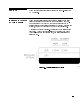
Frequency Range Resolution Agilent 83623L: Agilent 83630L: Agilent 83640L: Agilent 83650L: 10 MHz to 20 GHz High Power 10 MHz to 26.5 GHz 10 MHz to 40 GHz 10 MHz to 50 GHz Standard: 1 kHz Option 008: 1 Hz Frequency Bands (for CW signals) Band 0 1 2 3 4 5 6 7 1 2 3 Frequency Range 10 MHz to < 2 GHz 2 GHz to < 7 GHz 7 GHz to < 13.5 GHz 13.5 GHz to < 20 GHz 20 GHz to < 26.5 GHz1 26.5 GHz to < 33.5 GHz2 33.5 GHz to < 38 GHz3 38 GHz to 50 GHz n 1 1 2 3 4 6 6 8 This band is 20 GHz to < 25.
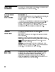
Synthesized Step Sweep Accuracy: Same as time base Minimum Step Size: Same as frequency resolution Number of Points: 2 to 801 Switching Time: Same as CW Dwell Time: 100 s to 3.2 s Synthesized List Mode Accuracy: Same as time base Minimum Step Size: Same as frequency resolution Number of Points: 1 to 801 Switching Time: Same as CW Dwell Time: 100 s to 3.
RF Output Output Power Maximum Leveled3 83623L 83630L Standard +15 Output Frequencies < 20 GHz Output Frequencies 20 GHz +13 +10 Output Frequencies < 26.5 GHz Output Frequencies > 26.5 GHz +10 +6 83640L 83650L Output Frequencies < 26.5 GHz +10 Output Frequencies 26.5 GHz and < 40 GHz +5 Output Frequencies 40 GHz +2.5 With attenuator (Option 001): Minimum settable output power is 0110 dBm. Maximum leveled output power is reduced by 1.5 dB to 20 GHz, 2.0 dB above 20 GHz, and 2.
Accuracy (dB)4 Speci cations apply in CW, step, list, manual sweep, and ramp sweep modes of operation. Power > +10 dBm > 010 dBm5 > 060 dBm 060 dBm < 2.0 61.2 60.6 60.9 61.4 Frequency (GHz) 2.0 and 20 > 2.0 and 40 61.3 60.7 60.9 61.0 61.2 61.5 61.7 > 40 61.7 62.0 62.5 Flatness (dB) Speci cations apply in CW, step, list, manual sweep, and ramp sweep modes of operation. Power > +10 dBm > 010 dBm5 > 060 dBm 060 dBm < 2.0 60.9 60.5 60.7 61.1 Frequency (GHz) 2.0 and 20 > 2.
020 dBm to maximum available power, can be o set using step attenuator. Analog Power Sweep Range: External Leveling Range At External HP/Agilent 33330D/E Detector: 036 to +4 dBm At External Leveling Input: 0200 V to 00.5 volts Bandwidth External Detector Mode: 10 or 100 kHz (sweep speed and modulation mode dependent), nominal Power Meter Mode: 0.7 Hz, nominal Source Match (internally leveled), typical6 < 20 GHz 1.6:1 SWR < 40 GHz 1.8:1 SWR < 50 GHz 2.0:1 SWR 6 2c-6 Specifications Typically 2.
Spectral Purity Spurious Signals Speci cations apply in CW, step, list, and manual sweep modes of operation. Harmonics Output 83623L 83630L 83640L 83650L Frequencies < 2.0 GHz Standard 2.0 and < 26.5 GHz Standard 26.
Non{Harmonically Related Output Frequencies: 9 < 2.0 GHz 2.0 and < 20 GHz 20 GHz and 26.5 GHz > 26.5 and 40 GHz > 40 GHz 9 060 060 058 054 052 Speci cation applies at output levels 0 dBm and below. Power{Line Related (< 300 Hz o set from carrier) 10 MHz to < 7 GHz 7 GHz to < 13.5 GHz 13.5 GHz to 20 GHz > 20 GHz to < 26.5 GHz 26.
Single-Sideband Phase Noise (dBc/Hz) Offset from Carrier Band(s) 10 MHz to < 7 GHz 7 GHz to < 13.5 GHz 13.5 GHz to 20 GHz > 20 GHz to < 26.5 GHz 26.5 GHz to < 38 GHz10 38 GHz to 50 GHz Residual FM (RMS, 50 Hz to 15 kHz bandwidth) 100 Hz 070 064 060 058 054 052 1 kHz 078 072 068 066 062 060 10 kHz 086 080 076 074 070 068 100 kHz 0107 0101 097 095 091 089 CW Mode or Sweep Widths n x 10 MHz: n x 60 Hz, typical Sweep Widths > n x 10 MHz: n x 15 kHz, typical 10 Frequency range is 26.
General Environmental Operating Temperature Range: 0 to 55 C Up to 4572 meters Humidity: 5 to 80% relative at +25 to 40 C Enclosure Protection: IP20, according to IEC 529 This product is designed for use in INSTALLATION CATEGORY II and POLLUTION DEGREE 2, per IEC 1010 and 664 respectively. EMC: Within limits of CISPR Pub. 11/1990 Group 1, Class A, and Mil-Std-461C Part 7 RE02 Altitude: Warmup Time Operation: Requires 30 minute warm-up from cold start at 0 to 55 C.
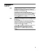
Inputs & Outputs Auxiliary Output Provides an unmodulated reference signal from 2 to 26.5 GHz at a typical minimum power level of 010 dBm. Nominal output impedance 50 ohms. (SMA female, rear panel.) RF Output Nominal output impedance 50 ohms. (Precision 3.5 mm male on 20 and 26.5 GHz models, 2.4 mm male on 40 and 50 GHz models, front panel.) External ALC Input Used for negative external detector or power meter leveling. Nominal input impedance 120 k , damage level 615 volts. See RF output speci cations.
Z-Axis Blanking/Markers Output Supplies positive rectangular pulse (Approximately +5 volts into 2 k ) during the retrace and bandswitch points of the RF output. Also supplies a negative pulse (05 volts) when the RF is at a marker frequency (intensity markers only). (BNC female, rear panel.) Volts/GHz Output Supplies voltage proportional to output frequency at 0.5 volts/GHz (internally switchable to 0.25 or 1 volt/GHz). Maximum output 18 volts. Minimum load impedance 2 k . Accuracy 60.5%, 610 mV, typical.
Option 806 Rack Slide Kit Used to rack mount 8360 while permitting access to internal spaces. Option 908 Rack Flange Kit Used to rack mount 8360 without front handles. Option 910 Extra Operating & Service Guides Provides a second copy of operating and service guides. Option 013 Rack Flange Kit Used to rack mount 8360 with front handles. Front handles are standard on the 8360. Option W30 Two Years Additional Return{To{Agilent Service Does not include biennial calibration.
3 Installation CAUTION Initial Inspection This chapter provides installation instructions for the Agilent 8360 L-Series swept CW generator and its accessories. It also provides information about initial inspection, damage claims, preparation for use, packaging, storage, and shipment. This product is designed for use in Installation Category II and Pollution Degree 2 per IEC 1010 and 664, respectively. Inspect the shipping container for damage.
Equipment Supplied All Agilent 8360 L-Series swept CW generators are sent from the factory with the following basic accessories: Rack handles (mounted) Power cord Software package A set of manuals The following adapters are also shipped with the swept CW generators: Table 3-1. Adapter Descriptions and Part Numbers Shipped with Each Swept CW Generator Model Agilent 83623L/Agilent 83630L Type-N (F) to 3.5 mm (F) 3.5 mm (F) to 3.5 mm (F) 1250-1745 5061-5311 2.4 mm (F) to K (F) 2.4 mm (F) to 2.
Preparation for Use Enclosure Protection Position the instrument according to the enclosure protection provided. This instrument does not protect against the ingress of water. This instrument protects against nger access to hazardous parts within the enclosure. Power Requirements The 8360 L-Series swept CW generators require a power source of 115 V (+10/025%) or 230 V (+10/015%), 48 to 66 Hz, single-phase. Power consumption is 400 VA maximum (30 VA in standby).
Power Cable In accordance with international safety standards, this instrument is equipped with a three-wire power cable. When connected to an appropriate power line outlet, this cable grounds the instrument cabinet. Figure 3-1 shows the styles of plugs available on power cables supplied with Agilent instruments. The part numbers indicated are part numbers for the complete power cable/plug set.
Figure 3-1.
Language Selection You can operate the swept CW generator using one of three external interface languages: SCPI, Analyzer language, or CIIL (Option 700). How to View or Change a Language Selection from the Front Panel Note To set a programming language from the front panel, the instrument language on the rear panel GPIB switch (L1, L2, and L3 shown in Figure 3-2) must be set to 7 (all 1s). The GPIB menu provides access to the swept CW generator's programming language: 1. Press SYSTEM 4 5. 2.
Figure 3-2. Rear Panel GPIB Switch GPIB Address Selection In certain applications, the swept CW generator acts as a controller for a power meter and a printer. Because of this, the address menu provides access not only to the swept CW generator's GPIB address, but also to the address at which the swept CW generator expects to see a power meter, and the address at which the swept CW generator expects to see a printer. (See Table 3-3 for factory-set addresses.) Table 3-3.
How to View or Change an GPIB Address from the Front Panel Note To set an GPIB address from the front panel, the instrument address on the rear panel GPIB switch (Figure 3-2) must be set to 31 (all 1s). 1. Press SYSTEM 4 5. 2. Select GPIB Menu Adrs Menu . 3. The swept CW generator displays the three address softkeys: 8360 Adrs , Meter Adrs , and Printer Adrs . 4. Select the desired softkey. 5. The swept CW generator displays the address selected for that instrument. 6.
Operating Environment CAUTION Temperature. The swept CW generator may be operated in environments with temperatures from 0 to +55 C. Humidity. The swept CW generator may be operated in environments with humidity from 5 to 80% relative at +25 to 40 C. However, protect the swept CW generator from temperature extremes, which can cause condensation within the instrument. Altitude. The swept CW generator may be operated at pressure altitudes up to 4572 meters (approximately 15,000 feet). Cooling .
Chassis Kits Rack Mount Slide Kit (Option 806) Option 806 swept CW generators are supplied with rack mount slides and the necessary hardware to install them on the swept CW generator. The following table itemizes the parts in this kit. Table 3-4.
Installation Procedure 1. 2. 3. 4. 5. Refer to Figure 3-3. Remove handle trim strips. Remove four screws per side. Using the screws provided, attach the rack mount anges to the outside of the handles. Remove the side straps and end caps. Remove the bottom and back feet and the tilt stands. Figure 3-3.
6. Refer to Figure 3-4. Remove the inner slide assemblies from the outer slide assemblies. 7. To secure the side covers in place, mount the inner slide assemblies to the instrument with the screws provided. 8. With the appropriate hardware, install the outer slide assemblies to the system enclosure. 9. Lift the swept CW generator into position. Align the inner and outer slide assemblies and slide the instrument into the rack. Realign the hardware as needed for smooth operation. Figure 3-4.
Rack Flange Kit for Swept CW Generators with Handles Removed (Option 908) Option 908 swept CW generators are supplied with rack anges and the necessary hardware to install them on the swept CW generator after removing the instrument handles. The following table itemizes the parts in this kit. Table 3-5.
Installation Procedure 1. Refer to Figure 3-5. Remove handle trim strips. 2. Remove the four screws on each side that attach the handles to the instrument; remove the handles. 3. Using the screws provided, attach the rack mount anges to the swept CW generator. 4. Remove the bottom and back feet and the tilt stands before rack mounting the instrument. Figure 3-5.
Rack Flange Kit for Swept CW Generators with Handles Attached (Option 913) Option 913 swept CW generators are supplied with rack anges and the necessary hardware to install them on the swept CW generator without removing the instrument handles. The following table itemizes the parts in this kit. Table 3-6.
Installation Procedure 1. Refer to Figure 3-6. Remove handle trim strips. 2. Remove the four screws on each side that attach the handles to the instrument. 3. Using the longer screws provided, attach the rack mount anges to the outside of the handles. 4. Remove the bottom and back feet and the tilt stands before rack mounting the instrument. Figure 3-6.
Storage and Shipment Environment The swept CW generator may be stored or shipped within the following limits: Temperature 040 to +75 C. Humidity 5% to 95% relative at 0 to +40 C. Altitude Up to 15240 meters. Pressure approximately 50,000 feet. The swept CW generator should be protected from sudden temperature uctuations that can cause condensation.
Package the Swept CW Generator for Shipment CAUTION Use the following steps to package the swept CW generator for shipment to Agilent Technologies for service: 1. Fill in a service tag (available at the end of Chapter 4) and attach it to the instrument. Please be as speci c as possible about the nature of the problem.
Converting HP/Agilent 8340/41 Systems to 8360 L-Series Systems The following paragraphs are intended to assist you in converting existing HP/Agilent 8340/8341-based systems to 8360 L-Series swept CW generator-based systems. The 8360 L-series swept CW generator may be used where no modulation requirements are needed. Both manual and remote operational di erences are addressed.
Manual Operation Compatibility The 8360 L-Series swept CW generators are designed to be, in all but very few cases, a complete feature superset of the HP/Agilent 8340/8341 synthesized sweepers. The most notable omissions are that the 8360 L-Series does not accept: line triggers (ie.
System Connections Note The 8510 Network Analyzer The 8360 L-Series swept CW generator is compatible with any HP/Agilent 8510 network analyzer with rmware revision 4.0 or higher. To upgrade rmware for an existing 8510, an HP/Agilent 11575C Revision 4.0 Upgrade Kit or an HP/Agilent 11575D Revision 5.0 Upgrade Kit is required. HP/Agilent 8510 revisions prior to 6.
The HP/Agilent 8757C/E Scalar Network Analyzer The connections between the analyzer and the 8360 L-Series are similar to the connections between the analyzer and the HP/Agilent 8340/8341. The 8360 L-Series di ers from the HP/Agilent 8340/8341 in one connection only. It is unnecessary to connect the modulator drive signal from the analyzer to the source. The 8360 L-Series internally produces the 27.8 kHz modulated signal necessary for AC mode measurements on the analyzer.
Remote Operation Language Compatibility The 8360 L-Series swept CW generators support three GPIB programming languages; network analyzer language, SCPI (Standard Commands for Programmable Instruments), and M.A.T.E. CIIL language (Option 700). Network Analyzer Language 8360 L-Series network analyzer language is syntactically and semantically identical to the HP/Agilent 8340/8341 GPIB mnemonics.
Features not available in one of the language modes are marked by a horizontal line in the corresponding column. In the interest of brevity all SCPI commands have been listed in their most concise form. For a complete and comprehensive listing of the swept CW generator SCPI commands, refer to \SCPI COMMAND SUMMARY" in Chapter 2. For explanations of SCPI, refer to \Getting Started Programming" in Chapter 1.
Table 3-9.
Table 3-9.
Table 3-9.
Table 3-9.
Table 3-9.
4 Operator's Check and Routine Maintenance WARNING Operator's Checks Service Information No operator serviceable parts inside. Refer servicing to qualified personnel. To prevent electrical shock, do not remove covers. The local operator's check (front panel use) allows the operator to make a quick check of the main swept CW generator functions prior to use. For delete front panel options of the Agilent 8360 L-Series, use the \Front Panel Emulator Software" to perform an operator's check.
Local Operator's Check Description Preliminary Check The preliminary check provides assurance that most of the internal functions of the swept CW generator are working. The main check provides a general check of the overall functions of the swept CW generator. No external equipment is needed. Each time the swept CW generator is turned on the swept CW generator performs a series of self tests on the internal CPU, power supplies, and front panel.
Main Check 5. 1. Press 4 2. Select Selftest (Full) . Check that all tests performed pass. 3. Press 4 5. If the display indicates a user preset was performed, select Factory Preset . Verify that the green SWEEP LED is blinking, the amber RF ON/OFF LED is on, and the red INSTR CHECK LED is o . 5. 4. Press 4 5. Select Tracking Menu . a. If the swept CW generator has Option 001, step attenuator, select Auto Track . Wait for the swept CW generator to nish peaking before continuing. b.
Routine maintenance consists of replacing a defective line fuse, cleaning the air lter, cleaning the cabinet, and cleaning the display. These items are discussed in the following paragraphs. Routine Maintenance Table 4-1. Fuse Part Numbers Voltage 115 V 230 V WARNING How to Replace the Line Fuse Note Fuse Part/Number 5 A 250 V 2110-0010 3 A 250 V 2110-0003 For continued protection against fire hazard, replace line fuse only with same type and rating.
How to Clean the Fan Filter Note The cooling fan located on the rear panel has a thin foam lter. How often the lter must be cleaned depends on the environment in which the swept CW generator operates. As the lter collects dust, the fan speed increases to maintain air ow (as the fan speed increases, so does the fan noise). If the lter continues to collect dust after the fan reaches maximum speed, air ow is reduced and the swept CW generator's internal temperature increases.
How to Clean the Cabinet WARNING To prevent electrical shock, disconnect the 8360 L-series swept CW generator from the mains before cleaning. Use a dry cloth or one slightly dampened with water to clean the external case parts. Do not attempt to clean internally. How to Clean the Display Filter The display of the swept CW generator is protected by a plastic display lter.
5 Instrument History This chapter is left blank until this manual requires changes.
A Address Function Group SYSTEM Menu Map 8 Description The 8360 Adrs softkey lets you change the GPIB address of the swept CW generator. Enter the address desired using the numeric entry keys or the up/down arrow keys. The address value may be set between 0 and 30. The swept CW generator stores the address value in non-volatile memory. The default address of the swept CW generator is 19.
NNNNNNNNNNNNNNNNNNNNNNNNNN Adrs Menu Programming Codes See Also SCPI: NONE, see the individual softkeys listed. Analyzer: NONE HP-IB Menu , softkeys listed above.
4ALC5 4ALC5 Function Group ALC Menu Map 1 Description This hardkey accesses the automatic level control (ALC) functions. Accesses the ALC bandwidth menu. ALC BW Menu Speci es the coupling factor of an Coupling Factor external coupling device and causes the display to indicate the power at the coupler main output. Disables the ALC leveling circuits. Leveling Mode ALCoff Relative power level is controlled by means of the level DAC and attenuator.
4ALC5 Speci es the operating range of an external power meter used in an external leveling setup. This causes the swept CW generator display to agree with the power meter's power indication. The following paragraphs explain the power control (leveling) function of the swept CW generator in detail.
4ALC5 Figure A-1.
4ALC5 Note Two terms are used in the following discussions: power output and ALC level. Power output means actual output power including the e ects of the attenuator. ALC level means power levels before the attenuator. In swept CW generators without attenuators, these two terms are equivalent.
4ALC5 5, the ALC level and attenuator are set automatically to provide the most accuracy for the power requested. Uncoupled Operation. In some applications it is advantageous to control the ALC level and attenuator separately, using combinations of settings that are not available in coupled operation. In uncoupled mode ( Uncoupl Atten ), when the desired power output is set via 5, only the ALC level is changed. The attenuator setting 4 is changed via Set Atten .
4ALC5 Figure A-2. Typical External Leveling Hookup NNNNNNNNNNNNNNNNNNNNNNNNNNNNNNNNNNNNNNNNNNNNNNNNNNNNNNNNNNNNNN NNNNNNNNNNNNNNNNNNNNNNNNNNNNNNNNNNNNNNNNNNNNNNNNNNNNNNNNNNNNNN ALC Disabled - Leveling Mode ALCoff , Leveling Mode Search In this con guration, the ALC is disabled, power is not sensed at any point, and therefore the absolute power level is uncalibrated (see Figure A-1). Direct and separate control of the RF modulator (p/o RF Components ) and the attenuator is possible.
4ALC5 4. While monitoring the internal detector, the RF modulator level is varied until the detected power is equivalent to the reference power measured in step 2. 5. Modulation is re-enabled if appropriate. These steps are performed in approximately 200 s and are repeated any time power or frequency is changed.
xxxxxxxxxxxxxxxxxxxxxxxxxxxxxxxxxxxxxxxxxxxxxxxxxxxxxx ALC Bandwidth Select Auto FFFFFFFFFFFFFFFFFFFFFFFFFFFFFFFFFFFFFFFFFFFFFFFFFFFFFF Function Group ALC Menu Map 1 Description This softkey sets the swept CW generator to choose the ALC bandwidth automatically depending on the current sweep and modulation conditions. An asterisk next to the key label indicates that this feature is active.
NNNNNNNNNNNNNNNNNNNNNNNNNNNNNNNN ALC BW Menu xxxxxxxxxxxxxxxxxxxxxxxxxxxxxxxxxxxxxxxxxxxxxxxxxxxxxx ALC Bandwidth Select Low FFFFFFFFFFFFFFFFFFFFFFFFFFFFFFFFFFFFFFFFFFFFFFFFFFFFFF Function Group ALC Menu Map 1 Description This softkey sets the swept CW generator to the ALC low bandwidth position (10 kHz). In this mode, the ALC bandwidth operates in a narrow bandwidth for all sweep and modulation conditions. An asterisk next to the key label indicates that this feature is active.
NNNNNNNNNNNNNNNNNNNNNNNNNNNNNNNN ALC BW Menu NNNNNNNNNNNNNNNNNNNNNNNNNNNNNNNNNNNNNNNNNNNNNNNNNNNNNNNNNNNNNNNNNNNNNNNNNN ALC Bandwidth Select Low See Also Sets the ALC bandwidth to the low bandwidth position (10 kHz), and to remain there for all sweep and modulation conditions.
ANALYZER STATUS REGISTER aaaaaaaaaaaaaaaaaaaaaaaaaaaaaaaaaaaaaaaaaaaaaaaaaa Ampl Markers Function Group MARKER Menu Map 3 Description Active markers are normally displayed as intensi ed dots on a CRT display. With Ampl Markers selected, active markers are displayed as amplitude spikes (an abrupt discontinuity in the sweep trace). The marker amplitude can be varied. The swept CW generator displays: --> AMPLITUDE MARKER SIZE: XXXX dB where XXXX represents an amplitude value.
ANALYZER STATUS REGISTER Bit # Decimal Value Function 7 128 STATUS BYTE (#1) 5 4 32 16 6 64 SRQ on new REQUEST frequencies SERVICE (RQS) or sweep time in e ect. Bit # 7 Decimal 128 Value Function Fault Indicator On 6 64 SRQ on SRQ on End of GPIB or syntax error.
ANALYZER STATUS REGISTER Bit 2: Oven for the reference crystal oscillator is not at operating temperature. Bit 3: External reference frequency is selected. Bit 4: RF is unlocked (UNLOCK appears in the message line). Use OF to determine the source of the unlocked output. This bit remains latched until this status byte has been read, or until cleared by the CS or CLEAR 719 commands. Bit 5: ac line power interruption has occurred since the last Instrument Preset.
Arrow Keys Function Group ENTRY Menu Map NONE Description This group of entry keys lets you manipulate numerical values in the active entry line. 4(5 and 4)5 arrow keys identify (by underlining) the digit to be changed. For example, if CW frequency is in the active entry line, and the display indicates: --> CW: 10005.000000 MHz you may wish to change the 5 to a 6. Press the 4)5 ve times until the underline is under the 5. Now use the rotary knob or the 4*5 to change the 5 to a 6.
4ASSIGN5 4ASSIGN5 Function Group USER DEFINED Menu Map NONE Description This hardkey lets you select any softkey and assign its function to 5 Menu. The following 1 of 12 user de ned keys in the 4 message appears on the swept CW generator display: --> Press MENU KEY to be assigned. Complete keypaths are assigned not just the key label. For example, assigning List Menu to the user de ned menu, copies the complete structure (keypath) of that key.
aaaaaaaaaaaaaaaaaaaaaaaaaaaaaaaaaaaaaaaaaaaaaaaaaaaaaaaaa Auto Fill Incr Function Group FREQUENCY, POWER Menu Map 2, 5 Description This softkey is used in two locations: Fltness Menu and List Menu . Flatness Menu - When selected, the swept CW generator waits for a frequency increment value to be entered. --> Increment: is displayed in the active entry area. A list of frequencies is created automatically, beginning at the auto ll start frequency and always ending with the auto ll stop frequency.
NNNNNNNNNNNNNNNNNNNNNNNNNNNNNNNNNNNNNNNN Auto Fill #Pts aaaaaaaaaaaaaaaaaaaaaaaaaaaaaaaaaaaaaaaaaaaaaaaaaaaaaaaaa Auto Fill #Pts Function Group FREQUENCY, POWER Menu Map 2, 5 Description This softkey is used in two locations: Fltness Menu and List Menu . Flatness Menu - When selected, the swept CW generator waits for a numeric value representing the number of correction points to be entered. --> Number of Correction Points: is displayed in the active entry area.
aaaaaaaaaaaaaaaaaaaaaaaaaaaaaaaaaaaaaaaaaaaaaaaaaaaaaaaaaaaaa Auto Fill Start Function Group FREQUENCY, POWER Menu Map 2, 5 Description This softkey is used in two locations: Fltness Menu and List Menu . The operation is the same in both applications. This softkey enables the entry of a start frequency used to determine the beginning frequency of the automatic lling array. The array is not created until either the increment value or the number of points is assigned.
NNNNNNNNNNNNNNNNNNNNNNNNNNNNNNNNNNNNNNNN Auto Fill Stop aaaaaaaaaaaaaaaaaaaaaaaaaaaaaaaaaaaaaaaaaaaaaaaaaaaaaaaaa Auto Fill Stop Function Group FREQUENCY, POWER Menu Map 2, 5 Description This softkey is used in two locations: Fltness Menu and List Menu . The operation is the same in both applications. This softkey enables the entry of a stop frequency used to determine the ending frequency of the automatic lling array.
aaaaaaaaaaaaaaaaaaaaaaaaaaaaaaaaaaaaaaaaaa Auto Track Function Group POWER, USER CAL Menu Map 5, 9 Description This softkey optimizes the tracking of the swept CW generator's output lter to the oscillator. Use it to maximize RF power output. The swept CW generator displays: Peaking At: XXXXX MHz, where XXXXX represents frequency values. Peaking begins at the low frequency end and steps through to the high end of the frequency range.
B aaaaaaaaaaaaaaaaaaaaaaaaaaaaaaaaaaaaaaaaaa Blank Disp Function Group SYSTEM Menu Map 8 Description When this softkey is selected, it causes the top four lines of the 5 key is pressed. display to blank and remain blank until the 4 Blanking the display prevents sensitive information from being displayed. As an added bene t, remote execution time is reduced because the display does not require refreshing. This key does not disable any other key functions.
C 4CENTER5 Function Group FREQUENCY Menu Map NONE Description This hardkey lets you select the center frequency for center 5, frequency/frequency span swept operation. When you press 4 the swept CW generator displays: --> CENTER: XXXXX MHz where XXXXX represents a frequency value. Use the entry area to set the desired value. Certain center frequency and frequency span combinations cause the swept CW generator to limit the value entered.
aaaaaaaaaaaaaaaaaaaaaaaaaaaaaaaaaaaaaaaaaaaaaaaaaaaaaa Center=Marker Function Group MARKER Menu Map 3 Description This softkey sets the center frequency of the sweep to the frequency of the most recently activated marker. Select any marker M1 . . . M5 , then select Center=Marker to change the center frequency of the sweep to that of the marker. The frequency span does not change unless the new sweep limits fall outside the frequency range of the swept CW generator.
NNNNNNNNNNNNNNNNNNNNNNNNNNNNNNNNNNN Clear Memory aaaaaaaaaaaaaaaaaaaaaaaaaaaaaaaaaaaaaaaaaaaaaaaaaa Clear Memory Function Group SYSTEM Menu Map 8 Description This softkey causes the swept CW generator to return to the factory preset instrument state, after writing alternating ones and zeroes over all state information, frequency lists, and save/recall registers. You can select the number of times to clear memory.
aaaaaaaaaaaaaaaaaaaaaaaaaaaaaaaaaaaaaaaaaaaaaa Clear Point Function Group POWER Menu Map 5 Description This softkey lets you change the correction value for the active frequency point to the \Unde ned" state.
CONNECTORS The open circuit voltage is TTL high and is internally pulled low when the swept CW generator stops its sweep. Externally forcing this input high will not cause damage or disrupt normal operation. 10 MHz REF INPUT accepts a 10 MHz 6100 Hz, 0 to +10 dBm reference signal for operation referenced to an external time base. Nominal input impedance is 50 . 10 MHz REF OUTPUT provides a 0 dBm, 10 MHz signal derived from the internal frequency standard of the swept CW generator.
CONNECTORS Pin # Table C-1. Pin Description of the Auxiliary Interface Function 1 2 No Connection Z-Axis Blanking/Markers 3 4 5 6 7 8 9 10 11 12 13 14 15 16 17 18 19 20 21 22 23 24 25 Spare Spare Low Stop Sweep +5.
CONNECTORS connector allows the swept CW generator to be connected to any other instrument or device on the interface bus. All GPIB instruments can be connected with GPIB cables and adapters. These cables are shown in the accompanying illustration. The adapters are principally extension devices for instruments that have recessed or crowded GPIB connectors. GPIB Figure C-2.
CONNECTORS Each instrument must have a unique GPIB address, ranging from 0 to 30 (decimal). Refer to 8360 Adrs for information on setting the swept CW generator's GPIB address. In a two-instrument system that uses just one GPIB cable, the cable length must not exceed 4 meters (13 ft). When more than two instruments are connected on the bus, the cable length to each instrument must not exceed 2 meters (6.5 ft) per unit. The total cable length between all units must not exceed 20 meters (65 ft).
CONNECTORS These codes are described completely in the IEEE Std 488-1978 document, published by The Institute of Electrical and Electronic Engineers, Inc., 345 East 47th Street, New York, New York 11017. SOURCE MODULE INTERFACE sends and receives digital and analog signals to and from an HP/Agilent 83550-Series millimeter-wave source module. With the source module connected, the swept CW generator assumes the characteristics of the source module. Refer to Leveling Point Module for more information.
CONNECTORS 015 V +15 V +8 V +5 V DIG GND MOD ANLG GND ANLG GND RET RF Output Connector Power supply. Range is 014.25 to 015.90 V. Power supply. Range is +14.25 to +16.40 V Power supply. Range is +7.75 to +8.25 V. Power supply. Range is +4.75 to +5.45 V. Digital ground. Source module analog ground. Analog ground return. The swept CW generator is equipped with a precision 3.5 mm male connector (2.4 mm male connector on 40 GHz models).
NNNNNNNNNNNNNNNNNNNNNNNNNNNNNNNNNNNNNNNNNNN CorPair Disable aaaaaaaaaaaaaaaaaaaaaaaaaaaaaaaaaaaaaa Copy List Function Group POWER Menu Map 5 Description This softkey lets you copy the frequency information of the frequency list to the atness correction menu. If there is no frequency list to copy, nothing happens.
aaaaaaaaaaaaaaaaaaaaaaaaaaaaaaaaaaaaaaaaaaaaaaaaaaaaaaaaaaaaa Coupling Factor Function Group ALC Menu Map 1 Description This softkey allows speci cation of the coupling factor of an external coupler/detector used to externally level the swept CW generator output power. Negative coupling factor values are required for valid entry. See \Speci cations" for the coupling factor range.
NNNNNNNNNNNNNNNNNNNNNNNNNNNNNNNNNNNNN CW/CF Coupled aaaaaaaaaaaaaaaaaaaaaaaaaaaaaaaaaaaaaaaaaaaaaaaaaaaaaa CW/CF Coupled Function Group FREQUENCY Menu Map 2 Description This softkey couples the CW function to the center frequency function. Any change initiated in either one of these parameters causes a change in the other.
D aaaaaaaaaaaaaaaaaaaaaaaaaaaaaaaaaaaaaaaaaaaaaaaaaaaaaa Dblr Amp Menu Function Group POWER Menu Map 5 Description This softkey accesses the doubler amp mode softkeys. These softkeys are applicable to instrument models with a doubler installed. The doubler has an integral ampli er whose operation is controlled by the instrument rmware. Its use depends on the frequency of operation and on the calibration constants set at the factory.
aaaaaaaaaaaaaaaaaaaaaaaaaaaaaaaaaaaaaaaaaaaaaa Delete Menu Function Group FREQUENCY, POWER Menu Map 2, 5 Description In the menu structure there are two occurrences of this softkey. It leads to the delete choices for both the frequency list menu and the power atness menu. Deletes the complete array. Delete All Deletes the active line in the array. Delete Current Appears in the power atness menu only. It Delete Undef deletes the points that are unde ned.
NNNNNNNNNNNNNNNNNNNNNNNNNNNNNNNNNNN Delete Undef aaaaaaaaaaaaaaaaaaaaaaaaaaaaaaaaaaaaaaaaaaaaaaaaaaaaaaaaa Delete Current Function Group FREQUENCY, POWER Menu Map 2, 5 Description In the menu structure there are two occurrences of this softkey. One occurs in the frequency list menu. The other occurs in the power atness menu. In the list menu application, the frequency entry and the associated o set and dwell values in the active line are deleted.
aaaaaaaaaaaaaaaaaaaaaaaaaaaaaaaaaaaaaaaaaaaaaaaaaa Delta Marker Function Group MARKER Menu Map 3 Description This softkey causes the di erence in frequency between two markers to appear on the swept CW generator display. The frequency di erence is indicated in the following format: --> DELTA MARKER |m - n| XXXXX MHz where m= the last marker activated, n= the reference marker, and XXXXX represents some frequency value. On a CRT display, the trace between the two selected markers is intensi ed.
NNNNNNNNNNNNNNNNNNNNNNNNNNNNNNNN Disp Status aaaaaaaaaaaaaaaaaaaaaaaaaaaaaaaaaaaaaaaaaaaaaaaaaaaaaa Delta Mkr Ref Function Group MARKER Menu Map 3 Description This softkey displays the ve markers available as the delta marker reference. The delta marker frequency is calculated using the equation: f m =fm0fmref where fm is the frequency of the active marker and fmref is the frequency of the reference marker.
NNNNNNNNNNNNNNNNNNNNNNNNNNNNNNNN Disp Status Function Table D-1.
NNNNNNNNNNNNNNNNNNNNNNNNNNNNNNNNNNNNNNNNNNNNNNNNNNNNNNNN Doubler Amp Mode Off aaaaaaaaaaaaaaaaaaaaaaaaaaaaaaaaaaaaaaaaaaaaaaaaaaaaaaaaaaaaaaaaaaaaaaaaaaaaaaaaaaaaa Doubler Amp Mode AUTO Function Group POWER Menu Map 5 Description This softkey is applicable to instrument models with a doubler installed. The doubler has an integral ampli er whose operation is controlled by the instrument rmware.
NNNNNNNNNNNNNNNNNNNNNNNNNNNNNNNNNNNNNNNNNNNNNNNNNNNNNNNN Doubler Amp Mode Off Programming Codes SCPI: POWer:AMPLi er:STATE ONjOFFj0j1 POWer:AMPLi er:STATE? Analyzer: See Also NONE NNNNNNNNNNNNNNNNNNNNNNNNNNNNNNNNNNNNNNNNN Dblr Amp Menu aaaaaaaaaaaaaaaaaaaaaaaaaaaaaaaaaaaaaaaaaaaaaaaaaaaaaaaaaaaaaaaaaaaaaaaaaaaaa Doubler Amp Mode On Function Group POWER Menu Map 5 Description This softkey is applicable to instrument models with a doubler installed.
NNNNNNNNNNNNNNNNNNNNNNNNNNNNNNNNNNNNN Dwell Coupled aaaaaaaaaaaaaaaaaaaaaaaaaaaaaaaaaaaaaaaaaaaaaaaaaaaaaa Dwell Coupled Function Group FREQUENCY Menu Map 2 Description This softkey lets you couple the dwell time for points in the stepped frequency sweep mode to the ramp sweep mode sweep time.
E aaaaaaaaaaaaaaaaaaaaaaaaaaaaaaaaaaaaaa 8360 Adrs Function Group SYSTEM Menu Map 8 Description This softkey lets you change the GPIB address of the swept CW generator. Enter the address desired using the numeric entry keys or the up/down arrow keys. The address value may be set between 0 and 30. The swept CW generator stores the address value in non-volatile memory. The default address of the swept CW generator is 19.
NNNNNNNNNNNNNNNNNNNNNNNNNNNNN Enter Corr Programming Codes See Also SCPI: NONE, see Fltness Menu Analyzer: NONE NNNNNNNNNNNNNNNNNNNNNNNNNNNNNNNNNNNNNN NNNNNNNNNNNNNNNNNNNNNNNNNNNNNNNNNNNNNN Fltness Menu \Optimizing Swept CW Generator Performance" in Chapter 1 aaaaaaaaaaaaaaaaaaaaaaaaaaaaaaaaaaaaaaaaaa Enter Freq Function Group POWER Menu Map 5 Description This softkey lets you enter a frequency point into the atness correction array.
NNNNNNNNNNNNNNNNNNNNNNNNNNNNNNNNNNNNNNNNNNN Enter List Freq Description Programming Codes See Also This softkey lets you enter a dwell time for a frequency point in the frequency list array. A frequency point must be entered before a dwell value can be accepted, otherwise the following error message appears: ERROR: Must first enter a List Frequency. The rotary knob and the up/down arrow keys let you scroll through the frequency points available to change the default dwell values.
aaaaaaaaaaaaaaaaaaaaaaaaaaaaaaaaaaaaaaaaaaaaaaaaaaaaaaaaaaaaaaaaaaaaa Enter List Offset Function Group FREQUENCY Menu Map 2 Description This softkey lets you enter an o set value for a frequency in the frequency list. A frequency point must be entered before a power value can be accepted, otherwise the following error message appears: ERROR: Must first enter a List Frequency.
NNNNNNNNNNNNNNNNNNNNNNNNNNNNNNNN Ext Det Cal 4ENTRY ON/OFF5 Function Group ENTRY Menu Map NONE Description This softkey lets you turn o (blank) the active entry area and disable the ARROW keys, rotary knob, and entry keys. When any function key (hard or soft) is pressed, the active entry area is 5 reactivated. The yellow LED, ENTRY ON, next to 4 indicates whether the entry area is active (LED on=active).
F aaaaaaaaaaaaaaaaaaaaaaaaaaaaaaaaaaaaaaaaaa Fault Menu Function Group SERVICE Menu Map 6 Description This softkey accesses the fault information softkeys. Use this softkey if a fault is indicated on the message line. Indicates the latched status of PEAK, TRACK, Fault Info 1 RAMP, SPAN, V/GHZ, and ADC. Indicates the latched status of EEROM, PWRON, Fault Info 2 CALCO, PLLZERO, PLLWAIT, and FNXFER. Indicates the latched status of CALYO, CALMAN, Fault Info 3 TMR CNFLCT, and SEARCH.
NNNNNNNNNNNNNNNNNNNNNNNNNNNNN Fault Menu Analyzer: See Also NONE Softkeys listed above. aaaaaaaaaaaaaaaaaaaaaaaaaaaaaaaaaaaaaaaaaaaaaaaaaa Fault Info 1 Function Group SERVICE Menu Map 6 Description This softkey displays the latched status of the following fault messages. PEAK FAIL Indicates that the peak algorithm is unable to align the YTM passband to the frequency of the YO. This fault indication is possible only if a peaking or autotrack routine has been initiated.
NNNNNNNNNNNNNNNNNNNNNNNNNNNNNNNNNNN Fault Info 2 Programming Codes See Also SCPI: See Fault Menu . Analyzer: NONE NNNNNNNNNNNNNNNNNNNNNNNNNNNNNNNN NNNNNNNNNNNNNNNNNNNNNNNNNNNNNNNN Fault Menu aaaaaaaaaaaaaaaaaaaaaaaaaaaaaaaaaaaaaaaaaaaaaaaaaa Fault Info 2 Function Group SERVICE Menu Map 6 Description This softkey displays the latched status of the following fault messages. EEROM FAIL Indicates that the EEROM (electrically erasable read only memory) has failed to store data properly.
NNNNNNNNNNNNNNNNNNNNNNNNNNNNNNNNNNN Fault Info 2 Programming Codes See Also SCPI: NONE Analyzer: NONE NNNNNNNNNNNNNNNNNNNNNNNNNNNNNNNN Fault Menu aaaaaaaaaaaaaaaaaaaaaaaaaaaaaaaaaaaaaaaaaaaaaaaaaa Fault Info 3 Function Group SERVICE Menu Map 6 Description This softkey displays the latched status of the following fault messages. CALYO FAIL Indicates that the YO adjusted at power-on or at preset is unable to calibrate.
NNNNNNNNNNNNNNNNNNNNNNNNNNNNNNNNNNN Fltness Menu aaaaaaaaaaaaaaaaaaaaaaaaaaaaaaaaaaaaaaaaaaaaaaaaaa Fltness Menu Function Group POWER Menu Map 5 Description This softkey reveals the softkeys in the atness correction menu that control user-de ned leveling parameters. Automatically creates a frequency list with all Auto Fill Incr points separated by the speci ed increment in a given frequency range.
NNNNNNNNNNNNNNNNNNNNNNNNNNNNNNNNNNN Fltness Menu The softkeys in this menu help front panel users enter and edit atness correction parameters. These editing softkeys are not accessible over GPIB. To load correction arrays over GPIB, the correction arrays must be created in the controlling program and then downloaded to the swept CW generator. The corresponding SCPI array creation and control commands are given after the description of this feature.
NNNNNNNNNNNNNNNNNNNNNNNNNNNNNNNNNNN Fltness Menu Figure F-2. User Flatness Correction Table as Displayed by the Swept CW Generator Theory of operation The unparalleled leveled output power accuracy and atness of the Agilent 8360 L-Series swept CW generator. This is achieved by using a new digital (versus analog) design to control the internal automatic leveling circuitry (ALC). An internal detector samples the output power to provide a dc feedback voltage.
NNNNNNNNNNNNNNNNNNNNNNNNNNNNNNNNNNN Fltness Menu Figure F-3. The Sources of ALC Calibration Correction Data If the correction frequency span is only a subset of the start/stop frequency span set on the source, no corrections are applied to the portion of the sweep that is outside the correction frequency span. The following example illustrates how the data is distributed within the user atness correction array.
NNNNNNNNNNNNNNNNNNNNNNNNNNNNNNNNNNN Fltness Menu When utilizing the user atness correction feature, do not exceed the swept CW generator ALC operating range. Exceeding the ALC range causes the output power to become unleveled and eliminates the bene ts of user atness correction. The ALC range can be determined by subtracting the minimum output power (020 dBm) from the maximum speci ed power.
NNNNNNNNNNNNNNNNNNNNNNNNNNNNNNNNNNN Fltness Menu command is set to array CORR:SOUR ARR, the array chosen is the 1601 point correction set. CORRection:SOURce[i]? Queries the source of correction. CORRection[:STATe] ONjOFFj1j0 Sets the switch on the user atness correction feature. This is the 5 on the front panel. same as pressing 4 CORRection:STATe? Queries the condition of the internal switch.
NNNNNNNNNNNNNNNNNNNNNNNNNNNNNNNN Freq Follow aaaaaaaaaaaaaaaaaaaaaaaaaaaaaaaaaaaaaaaaaaaaaaaaaaaaaa Freq Cal Menu Function Group USER CAL Menu Map 9 Description This softkey accesses the sweep span calibration menu. Swp Span Cal Always Performs a sweep span calibration each time the frequency span is changed. Performs a sweep span calibration.
FREQUENCY 4MENU5 Function Group FREQUENCY Menu Map 2 Description This hardkey allows access to the frequency functions listed below. When this feature is on, the center CW/CF Coupled frequency and the CW frequency is kept equal. Changing either the center frequency or the CW frequency causes the other to change to the same value. An asterisk next to the key label indicates that this feature is active. Freq Mult Sets the frequency multiplier value and applies it to all frequency parameters.
NNNNNNNNNNNNNNNNNNNNNNNNNN Freq Mult aaaaaaaaaaaaaaaaaaaaaaaaaaaaaaaaaaaaaa Freq Mult Function Group FREQUENCY Menu Map 2 Description This softkey lets you set a frequency multiplier value and applies it to all frequency parameters. Any integer value between and including 636 is accepted. Changing the multiplier value changes the display, it does not a ect the output of the swept CW generator. For example: 1. Set the start frequency to 4 GHz. 2. Set the stop frequency to 10 GHz. 3.
aaaaaaaaaaaaaaaaaaaaaaaaaaaaaaaaaaaaaaaaaaaaaa Freq Offset Function Group FREQUENCY Menu Map 2 Description This softkey lets you set a frequency o set value and applies it to all frequency parameters. The frequency o set ranges between and including 6110.0 GHz. Changing the frequency o set value changes the display but does not a ect the output frequency.
NNNNNNNNNNNNNNNNNNNNNNNNNNNNNNNN FullUsr Cal Programming Codes See Also SCPI: See the individual types of calibration.
G aaaaaaaaaaaaaaaaaaaaaaaaaaaaaaaaaaaaaaaaaaaaaaaaaa Global Dwell Function Group FREQUENCY Menu Map 2 Description This softkey is used to set a dwell time value for all points in the frequency list array.
H GPIB Address To set the swept CW generator's GPIB address, refer to \Address" in this manual. aaaaaaaaaaaaaaaaaaaaaaaaaaaaaaaaaaaaaaaaaa HP-IB Menu Function Group SYSTEM Menu Map 8 Description This softkey reveals the softkeys in the GPIB control menu. Reveals the softkeys that Adrs Menu allow GPIB addresses to be changed. Sets analyzer as the external Programming Language Analyzr interface language. Sets CIIL as the external Programming Language CIIL interface language.
L xxxxxxxxxxxxxxxxxxxxxxxxxxxxxxxxxxxxxxxxxxxxxxxxxxxxxx Leveling Mode ALCoff FFFFFFFFFFFFFFFFFFFFFFFFFFFFFFFFFFFFFFFFFFFFFFFFFFFFFF Function Group ALC Menu Map 1 Description This softkey lets you open the ALC loop. Direct and separate control of the linear modulator circuit (LVL DAC) and attenuator (ATN) is possible (see Figure A-1). The power level must be set using an external indicator (power meter/sensor).
xxxxxxxxxxxxxxxxxxxxxxxxxxxxxxxxxxxxxxxxxxxxxxxxxxxxxx Leveling Mode Normal FFFFFFFFFFFFFFFFFFFFFFFFFFFFFFFFFFFFFFFFFFFFFFFFFFFFFF Function Group ALC Menu Map 1 Description This softkey lets you set the leveling mode of the swept CW generator to continuous leveling at the desired leveling point. In this mode, the RF OUTPUT is controlled by the automatic level control (ALC) circuit, otherwise referred to as the leveling loop.
NNNNNNNNNNNNNNNNNNNNNNNNNNNNNNNNNNNNNNNNNNNNNNNNNNNNNNNN Leveling PointIntrnl Programming Codes See Also SCPI: POWer:ALC:STATe SEARch Analyzer: SHA1 , Pulse Modulation \Working with Spectrum Analyzers/Reverse Power E ects" in Chapter 1 4ALC5 xxxxxxxxxxxxxxxxxxxxxxxxxxxxxxxxxxxxxxxxxxxxxxxxxxxxxxxxx Leveling Point ExtDet FFFFFFFFFFFFFFFFFFFFFFFFFFFFFFFFFFFFFFFFFFFFFFFFFFFFFFFFF Function Group ALC Menu Map 1 Description This softkey lets you set the swept CW generator to accept an external feedba
NNNNNNNNNNNNNNNNNNNNNNNNNNNNNNNNNNNNNNNNNNNNNNNNNNNNNNNN Leveling PointIntrnl Menu Map 1 Description This softkey lets you set the swept CW generator to level at the output of the directional coupler located inside the swept CW generator. An asterisk next to the key label indicates that this feature is active.
LINE SWITCH xxxxxxxxxxxxxxxxxxxxxxxxxxxxxxxxxxxxxxxxxxxxxxxxxxxxxxxxx Leveling Point PwrMtr FFFFFFFFFFFFFFFFFFFFFFFFFFFFFFFFFFFFFFFFFFFFFFFFFFFFFFFFF Function Group ALC Menu Map 1 Description This softkey lets you set the swept CW generator to level at the power sensor of an external power meter. This mode of operation requires a feedback connection from the power meter to the EXT ALC BNC located on the swept CW generator. An asterisk next to the key label indicates that this feature is active.
aaaaaaaaaaaaaaaaaaaaaaaaaaaaaaaaaaaaaa List Menu Function Group FREQUENCY Menu Map 2 Description This softkey allows access to the frequency list functions. Automatically creates a frequency list using the Auto Fill Incr user-speci ed increment value. Automatically creates a frequency list Auto Fill #Pts containing a user-speci ed number of points. Auto Fill Start Allows the entry of a start frequency for the frequency list. Allows the entry of a stop frequency for the Auto Fill Stop frequency list.
NNNNNNNNNNNNNNNNNNNNNNNNNN List Menu 2. If the minimum and maximum frequencies of the swept CW generator frequency range are not the endpoints desired for the frequency list, use the Auto Fill Start and Auto Fill Stop softkeys to de ne the frequency list endpoints. Then, use either the Auto Fill Incr or Auto Fill #Pts softkeys to create the list. A list created by this method is ordered with the lowest frequency as the rst point and the highest frequency as the last point of the frequency list.
NNNNNNNNNNNNNNNNNNNNNNNNNN List Menu LIST[:POWer]:CORRection:POINts? [MAXimumjMINimum] In the above three commands, the swept CW generator responds with the number of points for the named parameter that are in the list array. If a particular list is shorter than another, an error is generated upon execution. An exception is made for the case where the shorter list is of length 1. In this case, the list of length 1 is treated as though it were a list of equal length, with all values the same.
NNNNNNNNNNNNNNNNNNNNNNNNNNNNNNNNNNNNNNNNNNNNNNNNNNNNNNNN List Mode Pt TrigExt xxxxxxxxxxxxxxxxxxxxxxxxxxxxxxxxxxxxxxxxxxxxxxxxxxxxxxxxxxxxxxxxxxxxx List Mode Pt Trig Bus FFFFFFFFFFFFFFFFFFFFFFFFFFFFFFFFFFFFFFFFFFFFFFFFFFFFFFFFFFFFFFFFFFFFF Function Group FREQUENCY Menu Map 2 Description This softkey lets you set the trigger point to be the GPIB.
4LOCAL5 Function Group INSTRUMENT STATE Menu Map NONE Description This hardkey lets you cancel remote operation and return the swept CW generator to front panel operation. The front panel keys are deactivated when the swept CW generator is operated remotely. If the external controller executes a LOCAL LOCKOUT command, pressing the 4 5 key does not return the swept CW generator to front panel control.
M aaaaaaaaaaaaaaaaaaaaaaaaaaaaaaaaaaaaaaaaaaaaaaaaaa M1--M2 Sweep Function Group MARKER Menu Map 3 Description This softkey lets you set the swept CW generator to start sweeping at the frequency of marker 1 (M1), and stop sweeping at the frequency of marker 2 (M2). M2 must have a higher frequency value than M1. If M1--M2 Sweep is activated when M2 is at a lower frequency than M1, the values of M1 and M2 are permanently interchanged.
NNNNNNNNNNNNNNNNNNNNNNNNNNNNNNNNNNN Manual Sweep resolution de ned by the 4(5 and 4)5 keys. Frequencies in the manual sweep mode are synthesized, just as they are in CW mode. There are two major di erences between manual sweep and a sweep generated by activating the CW function and rotating the rotary knob or pressing the ARROW keys. 1.
4MARKER5 4MARKER5 Function Group MENU SELECT Menu Map 3 Description This hardkey allows access to the marker functions. Causes the swept CW generator to display Ampl Markers markers as an amplitude pulse. Changes the swept CW generator's center Center=Marker frequency to the value of the most recently activated marker. Delta Marker Displays the frequency di erence between the active marker and the marker designated by the softkey Delta Mkr Ref .
aaaaaaaaaaaaaaaaaaaaaaaaaaaaaaaaaaaaaa Marker M1 Function Group MARKER Menu Map 3 Description The softkeys labeled Marker M1 through Marker M5 function identically. The softkey turns the marker o /on. When an asterisk appears next to the key label, it indicates that the marker is on, but not necessarily active. A marker is only active when it is indicated in the active entry area. The active entry area displays the active marker and its frequency value.
NNNNNNNNNNNNNNNNNNNNNNNNNN Marker M3 aaaaaaaaaaaaaaaaaaaaaaaaaaaaaaaaaaaaaa Marker M2 Function Group MARKER Menu Map 3 Description See MARKER Programming Codes NNNNNNNNNNNNNNNNNNNNNNNNNNNNN SCPI: MARKer2[:FREQuency] [freq su x] or MAXimumjMINimum MARKer2:STATe ONjOFFj1j0 Analyzer: See Also M1 M2 function on, M0 function o .
aaaaaaaaaaaaaaaaaaaaaaaaaaaaaaaaaaaaaa Marker M4 Function Group MARKER Menu Map 3 Description See MARKER Programming Codes NNNNNNNNNNNNNNNNNNNNNNNNNNNNN SCPI: MARKer4[:FREQuency] [freq su x] or MAXimumjMINimum MARKer4:STATe ONjOFFj1j0 Analyzer: See Also M1 M4 function on, M0 function o .
NNNNNNNNNNNNNNNNNNNNNNNNNNNNNNNNNNNNNNNNNNNNNN Measure Corr All aaaaaaaaaaaaaaaaaaaaaaaaaaaaaaaaaaaaaaaaaaaaaaaaaaaaaaaaaaaaa Markers All Off Function Group MARKER Menu Map 3 Description This softkey lets you turn all the markers o . The frequency value given to the markers remains in memory and will be recalled when the marker softkeys are pressed again. Softkeys Ampl Markers , Center=Marker , and M1--M2 Sweep are not a ected by turning the markers o .
xxxxxxxxxxxxxxxxxxxxxxxxxxxxxxxxxxxxxxxxxxxxxxxxxx Measure Corr Current FFFFFFFFFFFFFFFFFFFFFFFFFFFFFFFFFFFFFFFFFFFFFFFFFF Function Group POWER Menu Map 5 Description This softkey lets you enable the swept CW generator to act as a controller to command an HP/Agilent 437B power meter to measure a single atness correction value at the current atness array frequency.
4MOD5 aaaaaaaaaaaaaaaaaaaaaaaaaaaaaaaaaaaaaaaaaa Meter Adrs Function Group SYSTEM Menu Map 8 Description In cases where the swept CW generator is capable of acting as a controller to an HP/Agilent 437B power meter, this softkey enables you to set the programming address of the power meter. The address value can be set from 0 to 30, with the factory default address set at 13. The address value is stored in non-volatile memory.
aaaaaaaaaaaaaaaaaaaaaaaaaaaaaaaaaaaaaaaaaaaaaa Module Menu Function Group 4ALC5 Menu Map 1 Description This softkey accesses the source module selection softkeys. Millimeter-wave source modules can be connected to the swept CW generator source module interface connectors (there is one each on the front and rear panels).
NNNNNNNNNNNNNNNNNNNNNNNNNNNNNNNNNNNNNNNNNNNNNNNNNNNNNN Module Select Front aaaaaaaaaaaaaaaaaaaaaaaaaaaaaaaaaaaaaaaaaaaaaaaaaaaaaaaaaaaaaaaaaaaaaaaaa Module Select AUTO Function Group POWER and FREQUENCY Menu Map 2 and 5 Description This command sets the automatic selection of the millimeter source module interface connector. The swept CW generator looks at both front and rear connectors and determines the type of source module (if any) connected.
NNNNNNNNNNNNNNNNNNNNNNNNNNNNNNNNNNNNNNNNNNNNNNNNNNNNNN Module Select Front Programming Codes SCPI: SYSTem:MMHead:SELect FRONtjREARjNONE SYSTem:MMHead:SELect? Analyzer: See Also NONE NNNNNNNNNNNNNNNNNNNNNNNNNNNNNNNNNNN Module Menu aaaaaaaaaaaaaaaaaaaaaaaaaaaaaaaaaaaaaaaaaaaaaaaaaaaaaaaaaaaaaaaaaaaaaaaaa Module Select None Function Group POWER and FREQUENCY Menu Map 2 and 5 Description This command disables millimeter source module sensing.
NNNNNNNNNNNNNNNNNNNNNNNN more n/m aaaaaaaaaaaaaaaaaaaaaaaaaaaaaaaaaaaaaaaaaaaaaaaaaaaaaaaaaaaaaaaaaaaaaaaaa Module Select Rear Function Group POWER and FREQUENCY Menu Map 2 and 5 Description This command causes the swept CW generator to examine only the rear panel source module interface connector to determine the type of source module (if any) connected. The instrument frequency limits and multiplier are altered according to the source module connected. However, the leveling point is not changed.
aaaaaaaaaaaaaaaaaaaaaaaaaaaaaaaaaaaaaaaaaaaaaaaaaaaaaa Mtr Meas Menu Function Group POWER Menu Map 5 Description This softkey accesses the meter measure softkeys. Measures atness correction values for all Meas Corr All frequency points in the atness correction array. Meas Corr Current Measures a atness correction value for the frequency point currently in the active line of the atness correction array.
P aaaaaaaaaaaaaaaaaaaaaaaaaaaaaaaaaaaaaaaaaaaaaaaaaaaaaaaaa Peak RF Always Function Group POWER, USER CAL Menu Map 5, 9 Description This softkey appears in two locations: the POWER Tracking Menu and the USER CAL Tracking Menu . The operation is the same in both locations. This softkey causes the swept CW generator, when in CW or manual-sweep output mode, to align the output lter (SYTM) so that its passband is centered on the RF output.
aaaaaaaaaaaaaaaaaaaaaaaaaaaaaaaaaaaaaaaaaaaaaaaaaa Peak RF Once Function Group POWER, USER CAL Menu Map 5, 9 Description This softkey appears in two locations: the POWER Tracking Menu and the USER CAL Tracking Menu . The operation is the same in both locations. This softkey causes an instantaneous, one-time execution of the peaking function when the swept CW generator is in the CW or manual sweep mode. It aligns the output lter (SYTM) so that its passband is centered on the RF output.
4POWER LEVEL5 When you press 4 5, the active entry area displays: --> POWER LEVEL: X.XX dBm, where X represents a numeric value. The data display area indicates: Power(dBm) INT: X.XX. POWER LEVEL 5 key controls In Normal, Uncoupled Attenuator, the 4 the Level DAC and Level Control Circuits (see Figure A-1) within the ALC level range (+25 to 020 dBm). The attenuator is uncoupled from the ALC system and is controlled separately with the Set Atten key.
4POWER LEVEL5 When you press 4 , the active entry area displays: POWER LEVEL5 --> ATTEN X dB, POWER LEVEL: X.XX dBm , where X represents a numeric value. The data display area indicates: Power(dBm) MTR: X.XX . 5 key controls the output In Normal, Module, the 4 power of the swept CW generator as compared to the feedback voltage from a millimeter-wave source module.
POWER 4MENU5 See Also POWER , CONNECTORS, Det Cal Menu , 4 Set Atten , Tracking Menu , Uncoupl Atten \Programming Typical Measurements" in Chapter 1 NNNNNNNNNNNNNNNNNNNNNNNNNNNNNNNNNNNNNN 4ALC5 NNNNNNNNNNNNNNNNNNNNNNNNNNNNN NNNNNNNNNNNNNNNNNNNNNNNNNNNNNNNNNNNNNNNNN , FLTNESS ON/OFF5 NNNNNNNNNNNNNNNNNNNNNNNNNNNNNNNNNNNNNNNNN 4MENU5 Function Group POWER Menu Map 5 Description This hardkey accesses the power function softkeys. Accesses the softkeys in the atness Fltness Menu correction menu.
POWER 4MENU5 Programming Codes See Also SCPI: NONE Analyzer: NONE Softkeys listed previously under this menu key, 4 5, 4 5, 4 5, and 4 5.
NNNNNNNNNNNNNNNNNNNNNNNNNNNNNNNN Power Slope aaaaaaaaaaaaaaaaaaaaaaaaaaaaaaaaaaaaaaaaaaaaaa Power Slope Function Group POWER Menu Map 5 Description This softkey lets you compensate for system, cable, and waveguide variations due to changes in frequency, by linearly increasing or decreasing power output as the frequency increases. RF slope values may range from 02.50 to +2.50 dB per GHz. The power at the beginning of the sweep equals the current power level.
aaaaaaaaaaaaaaaaaaaaaaaaaaaaaaaaaaaaaaaaaaaaaa Power Sweep Function Group POWER Menu Map 5 Description This softkey enables the power sweep function. RF output power can be swept both positively and negatively over a selected range. The level of the power sweep starting point is the power level programmed. Power sweep widths can be 45 dB wide in either direction. However, the settable power sweep range is dependent on the ALC level set.
4PRESET5 4PRESET5 Function Group INSTRUMENT STATE Menu Map NONE Description This hardkey (green) causes the swept CW generator to perform a short version of self-test, and initializes the swept CW generator to a standard starting con guration. Two states can be de ned for the standard con guration: Factory or User. Press 4 5 at any time to test the swept CW generator and restore to a standard con guration.
xxxxxxxxxxxxxxxxxxxxxxxxxxxxxxxxxxxxxxxxxxxxxx Preset Mode Factory FFFFFFFFFFFFFFFFFFFFFFFFFFFFFFFFFFFFFFFFFFFFFF Function Group SYSTEM Menu Map 8 Description This softkey sets the standard starting con guration of the swept 5 key is pressed, as set by the CW generator when the 4 manufacturer. An asterisk next to the key label indicates that this feature is active. The following is a description of the con guration. Start sweep at the minimum speci ed frequency.
NNNNNNNNNNNNNNNNNNNNNNNNNNNNNNNNNNN Printer Adrs aaaaaaaaaaaaaaaaaaaaaaaaaaaaaaaaaaaaaaaaaaaaaaaaaaaaaaaaaaaaaaaaa Preset Mode User Function Group SYSTEM Menu Map 8 Description This softkey sets the standard starting con guration of the 5 key is pressed, as set swept CW generator when the 4 by the user. You can de ne any starting conditions: Set up the swept CW generator with the conditions you want, then select 5, the swept Preset Mode User .
4PRIOR5 Function Group MENU SELECT Menu Map NONE Description This hardkey lets you view previous menus. All menus visited from the last preset are remembered and displayed in a \last-visited- rst-seen" order. Refer to Figure P-1, and follow the arrow paths as indicated. Figure P-1. How 4PRIOR5 Works The sequence of keystrokes that created the movement shown in Figure P-1 is: 1. FREQUENCY 4 5 2. more 1/2 3. List Menu 4. Delete Menu 5. 4 5 6. 4 5 7.
NNNNNNNNNNNNNNNNNNNNNNNNNNNNNNNNNNNNNNNNNNNNNNNNNNNNNNNNNNNNNNNNNNNNNN Programming Language CIIL Programming Codes See Also SCPI: NONE Analyzer: NONE NNNNNNNNNNNNNNNNNNNNNNNNNN more n/m xxxxxxxxxxxxxxxxxxxxxxxxxxxxxxxxxxxxxxxxxxxxxxxxxxxxxxxxxxxxxxxxxxxxx Programming Language Analyzr FFFFFFFFFFFFFFFFFFFFFFFFFFFFFFFFFFFFFFFFFFFFFFFFFFFFFFFFFFFFFFFFFFFFF Function Group SYSTEM Menu Map 8 Description This softkey lets you select Analyzer Language as the swept CW generator's interface language.
NNNNNNNNNNNNNNNNNNNNNNNNNNNNNNNNNNNNNNNNNNNNNNNNNNNNNNNNNNNNNNNNNNNNNN Programming Language CIIL Description Programming Codes See Also This softkey lets you select CIIL as the swept CW generator's external interface language. The use of this language requires the M.A.T.E. option (Option 700) to be installed. Any commands issued within 100 ms of a change in language may be ignored or lost. An asterisk next to the key label indicates that this feature is active.
NNNNNNNNNNNNNNNNNNNNNNNNNNNNNNNNNNNNNNNNNNNNNNNNNNN Pulse On/OffScalar aaaaaaaaaaaaaaaaaaaaaaaaaaaaaaaaaaaaaaaaaaaaaaaaaa Pt Trig Menu Function Group FREQUENCY Menu Map 2 Description This softkey accesses the list mode point trigger softkeys. Automatically steps the swept CW List Mode Pt Trig Auto generator to the next point in the frequency list. Steps the swept CW generator to List Mode Pt Trig Bus the next point in the frequency list when an GPIB trigger is received.
NNNNNNNNNNNNNNNNNNNNNNNNNNNNNNNNNNNNNNNNNNNNNNNNNNN Pulse On/OffScalar Programming Codes SCPI: PULSe:SOURce SCALar PULSe[:STATe] ONjOFFj1j0 Analyzer: See Also SHPM function on, PM0 function o . , Chapter 3 4ALC5 4MOD5 aaaaaaaaaaaaaaaaaaaaaaaaaaaaaaaaaaaaaaaaaaaaaaaaaaaaaa Pwr Mtr Range Function Group 4ALC5 Menu Map 1 Description This softkey lets you specify a range of operation (from +20 to 060 dBm) for an external power meter, when a power meter is used to level power externally.
R 4RECALL5 Function Group SYSTEM Menu Map 8 Description This hardkey retrieves a front panel setting that was previously stored in a SAVE register (1 through 8). Programming Codes See Also SCPI: *RCL The above is an IEEE 488.2 common command. Analyzer: RCn, where n= a numeric value from 0 to 9.
NNNNNNNNNNNNNNNNNNNNNNNNNNNNNNNNNNN Ref Osc Menu NNNNNNNNNNNNNNNNNNNNNNNNNNNNNNNNNNNNNNNNNNNNNNNNNNNNNNNNNNNNNNNNNNNNNNNNNNNNN 10 MHz Freq Standard None Programming Codes See Also Sets the swept CW generator to free-run operation, where no frequency standard is used. SCPI: ROSCillator:SOURce:INTernaljEXTernaljNONe Analyzer: NONE Softkeys listed above. 4RF ON/OFF5 Function Group Menu Map Description Programming Codes See Also POWER NONE 5. This hardkey turns the RF power output on or o .
S 4SAVE5 Function Group SYSTEM Menu Map 8 Description This hardkey allows up to eight di erent front panel settings to be stored in memory registers 1 through 8. Swept CW generator 5 key. A memory settings can then be recalled with the 4 register can be alternated with the current front panel setting using the Atrnate Regs softkey.
aaaaaaaaaaaaaaaaaaaaaaaaaaaaaaaaaaaaaa Save Lock Function Group SYSTEM Menu Map 8 Description This softkey lets you disable the save function. It prohibits the saving of the present instrument state into a save/recall memory register. If this function is active, an error message is displayed. An asterisk next to the key label indicates that this function is active. Programming Codes See Also SCPI: NONE Analyzer: SHSV locks the registers, SHRC unlocks the registers.
SCPI Conformance Information SCPI Conformance Information The Agilent 8360 L-Series swept CW generators conform to the 1990.0 version of SCPI.
SCPI Conformance Information :BANDwidthj:BWIDth :AUTO :AUTO? :BANDwidthj:BWIDth? :ATTenuation :AUTO :AUTO? :ATTenuation? [:LEVel] [:LEVel]? :MODE :MODE? :RANGe :SPAN :SPAN? :STARt :STARt? :STOP :STOP? :PULM :SOURce :SOURce? :STATe :STATe? :ROSCillator :SOURce :AUTO :AUTO? :SOURce? :STATus :OPERation :CONDition? :ENABle :ENABle? [:EVENt]? :NTRansition :NTRansition? :PTRansition :PTRansition? :PRESet :QUEStionable :CONDition? :ENABle :ENABle? [:EVENt]? :NTRansition :NTRansition? :PTRansition :PTRansition? :S
SCPI Conformance Information :DWELl :AUTO :AUTO? :DWELl? :GENeration :GENeration? :MODE :MODE? :POINts :POINts? :STEP :STEP? :TIME :AUTO :AUTO? :LLIMit :LLIMit? :TIME? :SYSTem :ALTernate :STATe :STATe? :ALTernate? :COMMunicate :GPIB :ADDRess :SECurity [:STATe] [:STATe]? :VERSion? :TRIGger [:IMMediate] :SOURce :SOURce? The following are the SCPI approved commands implemented by the 8360L-Series swept CW generators: Instrument-speci c diagnostic commands: :DIAGnostics :ABUS :AVERage :AVERage? :STATus? :ABUS?
SCPI Conformance Information :PRINter :ADDRess :ADDRess? :IORW :IORW? :LED :ACTive :ACTive? :ERRor :ERRor? :IOCHeck :IOCHeck? :OSC :FNCW :FNDN :FNUP :HARM :IF :SAMP :YO :OUTPut :BANDcross? :FAULts? :FREQs? :UNLocks? :YODacs? :YTMDacs :SRECeiver :ASTate :ASTate? :BCRoss :MODE :MODE? :RSWeep :SWAP :SWAP? :BUCKet :DIVider :DIVider? :SWEep :ARRay[0j1] :LOCK :LOCK? :ARRay[0j1]? :RESult? :TEST :CONTinue :DATA :DESC? :MAXimum? S-6 Operating and Programming Reference
SCPI Conformance Information :MINimum? :VALue? :DISable :ENABle [:EXECute] :LOG :SOURce :SOURce? [:STATe] [:STATe]? :LOOP :LOOP? :NAME? :PATCh :DATA :DATA? :POINts? :DELete :POINts? :RESult? :TINT? The following are the commands implemented by the 8360 L-Series swept CW generators which are not part of the SCPI de nition: :CALibration :ADJust :A4:VCO :A5:LGAin :A6:VCO :A6:SMATch :A6:LGAin :A6:IFGain :A9:OFFSet :A10:MGAin :A13:REFerence :A13:GAIN :A14:SRAMp :CONStants :DEFault :NAME? :RECall :SAVE :CONStant
SCPI Conformance Information :ATTenuation? :DETector :INITiate? :NEXT? :FLATness :INITiate? :NEXT? :RANGe :RANGe? :POWer :ARRay :POINts? :ARRay? :ATTenuation :ATTenuation? :EXTernal :ARRay :POINts? :ARRay? :RANGe :RANGe? :TYPE :TYPE? :VALue :VALue? :ZERO :TYPE :VALue :VALue? :RANGe :RANGe? :RECall :SAVE :ZERO :ALL :SECurity :CODE :STATe :STATe? :SPAN :AUTO :AUTO? [:EXECute] :TRACk :CORRection :ARRay[i] :ARRay[i]? :FLATness :POINts? :FLATness? S-8 Operating and Programming Reference
SCPI Conformance Information :SOURce[i] :SOURce[i]? [:STATe] [:STATe]? :FREQuency :MULTiplier :STATe :STATe? :MULTiplier? :OFFSet :STATe :STATe? :OFFSet? :STEP :AUTO :AUTO? [:INCRement] [:INCRement]? :INITiate :CONTinuous :CONTinuous? [:IMMediate] :LIST :MANual :MANual? :MODE :MODE? [:POWer] :CORRection :POINts? :CORRection? :TRIGger :SOURce :SOURce? :MARKer[n] :AMPLitude [:STATe] [:STATe]? :VALue :VALue? :DELTa? :MODE :MODE? :POWer :ALC :CFACtor :CFACtor? :SOURce :SOURce? [:STATe] Operating and Programmin
SCPI Conformance Information [:STATe]? AMPLi er :STATE :AUTO :AUTO? :STATE? :CENTer :CENTer? :OFFSet :STATe :STATe? :OFFSet? :SEARch :SLOPe :STATe :STATe? :SLOPe? :STATe :STATe? :STEP :AUTO :AUTO? [:INCRement] [:INCRement]? :STATus :MSIB :CONDition? :ENABle :ENABle? [:EVENt]? :NTRansition :NTRansition? :PTRansition :PTRansition? :SREceiver :CONDition? :ENABle :ENABle? [:EVENt]? :NTRansition :NTRansition? :PTRansition :PTRansition? :SWEep :CONTrol :STATe :TYPE :MANual :POINt :POINt? S-10 Operating and Progr
SCPI Conformance Information [:RELative] [:RELative]? :MARKer :STATe :STATe? :XFER :TRIGger :SOURce :SOURce? :SYSTem :DUMP :PRINter :PRINter? :ERRor? :KEY :ASSign :CLEar [:CODE] [:CODE]? :DISable :ENABle :LANGuage :MMHead :SELect :AUTO :AUTO? :SELect? :PRESet [:EXECute] :SAVE :TYPE :SECurity :COUnt :COUnt? :TRIGger :ODELay :ODELay? :TSWeep :UNIT :POWer :POWer? Operating and Programming Reference S-11
SCPI COMMAND SUMMARY Introduction IEEE 488.2 Common Commands This entry is organized as follows: 1. IEEE 488.2 common commands in alphabetical order. 2. Command table of SCPI programming commands. 3. Alphabetical listing of commands with descriptions. *CLS Clear the Status Byte, the Data Questionable Event Register, the Standard Event Status Register, the Standard Operation Status Register, the error queue, the OPC pending ag, and any other registers that are summarized in the Status Byte.
SCPI COMMAND SUMMARY *OPT? This returns a string identifying any device options. *RCL The instrument state is recalled from the speci ed memory register. The value range is from 0 to 8.
SCPI COMMAND SUMMARY MARKer[n]:MODE FREQuency MARKer[n][:STATe] OFF POWer:ALC:BANDwidth:AUTO ON POWer:ALC:CFACtor 016 DBM POWer:ALC[:SOURce] INTernal POWer:AMPLifier:STATE:AUTO ON POWer:ATTenuation:AUTO ON POWer:CENTer 0 DBM POWer[:LEVel] 0 DBM POWer:MODE FIXed POWer:SLOPe 0 POWer:SLOPe:STATe OFF POWer:SPAN 0 DB POWer:STARt 0 DBM POWer:STATe OFF POWer:STEP:AUTO ON POWer:STEP[:INCRement] 10 DB POWer:STOP 0 DBM PULM:SOURce SCALar PULM:STATe OFF ROSCillator:SOURce:AUTO ON SWEep:DWELl 100 s SWEep:DWELl:AUTO OF
SCPI COMMAND SUMMARY *STB? Queries the Status Byte. This is a non-destructive read. *TRG This command performs the same function as the Group Execute Trigger command de ned by IEEE 488.1. *TST? A full selftest is performed, without data logging or looping, and returns one of the following error codes: Error Code 0 1 2 3 4 5 01 De nition Test passed. Test failed. Test not run yet. (This is an unlikely event.) Test aborted. Can not execute the test. Can not execute the test, test skipped.
SCPI COMMAND SUMMARY Command Table S-1.
SCPI COMMAND SUMMARY Table S-1.
SCPI COMMAND SUMMARY Table S-1.
SCPI COMMAND SUMMARY Table S-1. 8360 SCPI COMMAND SUMMARY (continued) Command Parameters Allowed Values Parameter Type1 :LIST dwell time extended numeric f0.
SCPI COMMAND SUMMARY Table S-1.
SCPI COMMAND SUMMARY Table S-1.
SCPI COMMAND SUMMARY Table S-1. 8360 SCPI COMMAND SUMMARY (continued) Command Parameters Allowed Values Parameter Type1 :SWEep :CONTrol :STATe dual source mode Boolean ONjOFFj1j0 :TYPE type of sweep control discrete MASTerjSLAVe settling time plus dwell time extended numeric 0.
SCPI COMMAND SUMMARY Table S-1.
SCPI COMMAND SUMMARY ABORt Causes the sweep in progress to abort and reset. If INIT:CONT is ON it immediately restarts the sweep. The pending operation ag (driving *OPC, *WAI, and *OPC?) undergoes a transition once the sweep is reset. CALibration:PEAKing:AUTO ON|OFF|1|0 CALibration:PEAKing:AUTO? Sets and queries the automatic peaking function. If AUTO is ON, then a peak is done at regular intervals automatically. After *RST, the setting is OFF. CALibration:PEAKing[:EXECute] Peaks the SYTM.
SCPI COMMAND SUMMARY PMETer MMHead Initiates a calibration of the power meter atness. Depends on value of CALibration:PMETer:RANGe. Initiates a calibration of the source module atness. Depends on value of CALibration:PMETer:RANGe. CALibration:PMETer:FLATness:NEXT? [lvl suffix] The parameter is the measured power that is currently produced by the swept CW generator. You must supply this parameter after measuring the power using an external power meter.
SCPI COMMAND SUMMARY pairs. This correction information is used to create a correction array that can be added to the internal calibration array. The correction entered is at the associated frequency. Frequencies in between frequency-correction pair values are determined by linear interpolation. If a value of START or STOP frequency is speci ed that is outside the limits of the speci ed frequencies, the correction applied at those points is 0 dB. After *RST, returns a MinFreq, 0 DB, MaxFreq, 0 DB response.
SCPI COMMAND SUMMARY Sets the GPIB address of the printer to use during some of the calibration procedures when the swept CW generator assumes GPIB control. *RST and power on do not e ect this command. The default is 1. The default value is set at memory initialization only. DIAGnostics:IORW , DIAGnostics:IORW? Performs a write to the I/O Device number speci ed in the rst and sets it to the value in the second .
SCPI COMMAND SUMMARY Signal Generator/8360 L-Series Swept CW Generator Service Guide to begin the troubleshooting procedure. DIAGnostics:TEST:CONTinue Causes the selftest execution to continue when paused for raw data examination. Does nothing in other conditions. DIAGnostics:TEST:DATA:DESC? Returns the description string of the raw data examined during a selftest. It returns \ " in other conditions. DIAGnostics:TEST:DATA:MAXimum? Returns the upper test limit for the raw data point examined.
SCPI COMMAND SUMMARY Selects and queries the raw data logging ON/OFF switch. Both commands are executable in selftest mode. After *RST, the setting is 0. DIAGnostics:TEST:LOOP ON|OFF|1|0 DIAGnostics:TEST:LOOP? Selects and queries the test looping ON/OFF switch. Both commands are executable in selftest mode. After *RST, the setting is 0. DIAGnostics:TEST:NAME? [] Queries the name of a selftest by number. If the number is not speci ed then an array of all the selftest names is returned.
SCPI COMMAND SUMMARY requested value. The start/stop frequencies are updated to re ect the changes based on the coupling equations. The swept CW generator uses \bumping" to move unspeci ed frequency parameters, but if the nal value of any of the frequency headers is the result of bumping, then an error is generated since the user is not getting what was speci ed. This means, to guarantee sequence independence requires sending the frequency pairs in a single message.
SCPI COMMAND SUMMARY FREQuency:MANual [freq suffix]|MAXimum|MINimum|UP|DOWN FREQuency:MANual? [MAXimum|MINimum] Sets and queries the manual frequency. This controls the output frequency in swept manual mode. The limits are START and STOP. *RST value is the same as FREQ:CENTER. See FREQ:CENTER for more information. FREQuency:MODE FIXed|CW|SWEep|LIST FREQuency:MODE? Sets and queries the switch that selects either swept, CW or list operation. *RST value is CW.
SCPI COMMAND SUMMARY Queries and turns the frequency o set o and on. After *RST, the setting is OFF. FREQuency:SPAN [freq suffix]|MAXimum|MINimum|UP|DOWN FREQuency:SPAN? [MAXimum|MINimum] Sets and queries the frequency span. See FREQ:CENTER information. for more FREQuency:STARt [freq suffix] |MAXimum|MINimum|UP|DOWN FREQuency:STARt? [MAXimum|MINimum] Sets and queries the START Frequency. See FREQ:CENTER for more information. *RST setting is MIN.
SCPI COMMAND SUMMARY analyzer compatible language take sweep and single sweep command can be achieved. LIST:DWELl {[time suffix]|MAXimum|MINimum}1*801 LIST:DWELl? [MAXimum|MINimum] Sets and queries the amount of time to dwell at each frequency. The number of dwells can be queried with LIST:DWELl:POINts?. This dwell is the time after completing phaselock and turning RF on before changing to the next frequency. After *RST, the value is 100 s (MIN).
SCPI COMMAND SUMMARY LIST:MODE LIST:TRIGger:SOURce How the list is played back. AUTO IMMediate AUTO BUS AUTO EXTernal MANual Don't care Each new frequency point is stepped to automatically, after waiting the speci ed DWELl time. Wait for a or *TRG over the GPIB before advancing to the next frequency in the list. Wait for a signal to be received on the external input before advancing to the next frequency in the list. Only the list point speci ed by LIST:MANual is played back.
SCPI COMMAND SUMMARY be used, there is really only a single value for all the markers. *RST value is 2 dB. MARKer[n]:AOFF Sets all the markers to OFF at once. While [n] may be used, there is really only a single switch for all the markers. MARKer[n]:DELTa? , This query returns the di erence in frequency between the two speci ed marker numbers.
SCPI COMMAND SUMMARY Power Subsystem Any place where dBm is accepted as a su x, any level su x is accepted also. In the absence of a su x, the units are assumed to be as set by the UNIT:POW command. POWer:ALC:BANDwidth|:BWIDth [freq suffix]|MAXimum|MINimum POWer:ALC:BANDwidth?|:BWIDth? [MAXimum|MINimum] Sets and queries the ALC bandwidth. This is actually not continuously variable, so the input is rounded to the nearest possible switch position.
SCPI COMMAND SUMMARY state. Programming a speci c value for POWer:AMPLifier:STATE sets POWer:AMPLifier:STATE:AUTO to OFF. *RST value is ON. POWer:ATTenuation [DB]|MAXimum|MINimum|UP|DOWN POWer:ATTenuation? [MAXimum|MINimum] Sets and queries the output attenuation level. Note that when setting the attenuator level to 10 dB the output power is decreased by 10 dB. Programming a speci ed attenuation sets POWer:ATTenuation:AUTO OFF.
SCPI COMMAND SUMMARY POWer:OFFSet [DB]|MAXimum|MINimum|UP|DOWN POWer:OFFSet? [MAXimum|MINimum] Sets and queries the power o set. This function changes mapping of absolute power parameters on input to and output from the swept CW generator. Changing this does not a ect the output power of the swept CW generator. Only the displayed parameters and query responses are changed. The equation implied by this is: The entered or displayed power = Hardware Power + O set After *RST, the value is 0.
SCPI COMMAND SUMMARY The *RST value is 0. POWer:SLOPe:STATe ON|OFF|1|0 POWer:SLOPe:STATe? Sets and queries the power slope state. *RST value is 0. POWer:SPAN [DB]|MAXimum|MINimum|UP|DOWN POWer:SPAN? [MAXimum|MINimum] The coupling equations for power sweep are exactly analogous to those for frequency sweep. Power sweep is allowed to be negative, unlike frequency sweeps. *RST value is 0.
SCPI COMMAND SUMMARY Sets and queries the reference oscillator selection switch. The command to set the switch will cause ROSC:SOUR:AUTO OFF to be done also. The *RST value is automatically determined. ROSCillator:SOURce:AUTO ON|OFF|1|0 ROSCillator:SOURce:AUTO? Sets and queries the automatic reference selection switch. The *RST value is 1. STATus:OPERation:CONDition? Queries the Standard Operation Condition register.
SCPI COMMAND SUMMARY Sets and queries the Data Questionable SRQ Enable register. The STATus:PRESet value is 0. STATus:QUEStionable[:EVENt]? Queries the Data Questionable Event Register. This is a destructive read. STATus:QUEStionable:NTRansition STATus:QUEStionable:NTRansition? Sets and queries the Negative TRansition Filter for the Data Questionable Status Register. The STATus:PRESet value is 0.
SCPI COMMAND SUMMARY Sets and queries the instrument, whether it is in master or slave mode. This applies in a dual source mode. *RST value is MASTer. SWEep:DWELl [time suffix]|MAXimum|MINimum SWEep:DWELl? [MAXimum|MINimum] Sets and queries the amount of time in seconds that the instrument stays (dwell) at each step after reporting a source settled SRQ and pulsing the Trigger Out line low. This one value is used at each step when in the SWE:TRIG:SOUR IMM mode of a stepped sweep.
SCPI COMMAND SUMMARY or a digitally stepped sweep. In either case, all of the other sweep subsystem functions apply. *RST is ANALog. SWEep:MANual:POINt |MAXimum|MINimum SWEep:MANual:POINt? [MAXimum|MINimum] Sets and queries the step point number to go to and lock. The value is a unitless value that is limited between 1 and the number of points requested. This command has no e ect on the instrument unless: the sweep mode is set to manual and the sweep generation is set to stepped mode.
SCPI COMMAND SUMMARY SWEep:STEP [freq suffix]|MAXimum|MINimum SWEep:STEP? [MAXimum|MINimum] Sets and queries the size of each frequency step. :STEP is governed by the equation: STEP = SPAN/POINTS. If you change step size then the number of points will be changed to span/step and a Parameter Bumped execution error is reported. If span or points are changed, then STEP= SPAN/POINTS. The step sweep command creates a coupling with sweeptime also.
SCPI COMMAND SUMMARY SYSTem:ALTernate |MAXimum|MINimum SYSTem:ALTernate? [MAXimum|MINimum] Sets and queries the save/recall register number to alternate the foreground state of the instrument. The *RST value is 1. SYSTem:ALTernate:STATe ON|OFF|1|0 SYSTem:ALTernate:STATe? Sets and queries the state of the Alternate State function. *RST setting is OFF. SYSTem:COMMunicate:GPIB:ADDRess Changes the GPIB's (General Purpose Interface Bus) address. The *RST value is 19.
SCPI COMMAND SUMMARY frequency limits and multiplier will be altered accordingly. However, the leveling point is not changed (see POWer:ALC:SOURce). SYSTem:PRESet[:EXECute] Sets the instrument to its \local operation" state. This is the same as pressing the front panel \green" key. There is no corresponding query. SYSTem:PRESet:SAVE Saves the present state so it can be used whenever the command is executed or the front panel \green" key is pressed.
SCPI COMMAND SUMMARY subsystem. This event does not a ect any other settings in this subsystem. This command has no e ect unless the instrument is in the wait for trig state. If the swept CW generator is in the wait for trig state, it performs its trigger action. This is an event and has no *RST condition.
SCPI STATUS REGISTER STRUCTURE S-48 Operating and Programming Reference
SCPI STATUS REGISTER STRUCTURE Operating and Programming Reference S-49
aaaaaaaaaaaaaaaaaaaaaaaaaaaaaaaaaaaaaaaaaaaaaaaaaaaaaa Security Menu Function Group SYSTEM Menu Map 8 Description This softkey accesses the security function softkeys. Blank Display Turns o the swept CW generator's data display, active entry, and message line areas. Writes alternating ones and zeros over all swept Clear Memory CW generator state functions and save/recall registers a selectable number of times, then returns the swept CW generator to the factory-preset state of operation.
NNNNNNNNNNNNNNNNNNNNNNNNNN Set Atten aaaaaaaaaaaaaaaaaaaaaaaaaaaaaaaaaaaaaaaaaaaaaaaaaaaaaaaaaaaaa Selftest (Full) Function Group SERVICE Menu Map 6 Description This softkey activates the self-test function of the swept CW generator.
4SINGLE5 Function Group SWEEP Menu Map 7 Description This hardkey selects single sweep mode, aborts any sweep in progress and initiates a single sweep at a rate determined by the sweep time function. If you press 4 5 in the middle of a continuous sweep, the sweep is aborted and the swept CW generator retraces to the starting point but does not start a sweep. Press 4 5 a second time to start the sweep. The amber LED above the hardkey is lit when the function is on.
4START5 4SPAN5 Function Group FREQUENCY Menu Map 2 Description This hardkey lets you set a value for the frequency span in the center frequency/frequency span mode of swept frequency operation. Press 4 5, and use the entry area to enter the desired value. The swept CW generator sweeps from one half the span below to one half above the center frequency. Certain center frequency and frequency span combinations cause the swept CW generator to limit the value entered.
4START5 Programming Codes SCPI: FREQuency:STARt [freq su x] or MAXimumjMINimumjUPjDOWN FREQuency:MODE SWEep Analyzer: See Also FA [HzjKzjMzjGz] , , FREQUENCY 4 5, 4 5, 4 5 \CW Operation and Start/Stop Frequency Sweep" in Chapter 1 \Programming Typical Measurements" in Chapter 1 4CENTER5 4CW5 MENU SPAN STOP aaaaaaaaaaaaaaaaaaaaaaaaaaaaaaaaaaaaaaaaaaaaaaaaaaaaaaaaaaaaaaaaa Start=M1 Stop=M2 Function Group MARKER Menu Map 3 Description This softkey changes the swept CW generator sta
NNNNNNNNNNNNNNNNNNNNNNNNNNNNNNNNNNNNNNNNNNNNNNNNNNNNNNNNNNNNNNNNN Start Sweep Trigger Bus xxxxxxxxxxxxxxxxxxxxxxxxxxxxxxxxxxxxxxxxxxxxxxxxxxxxxx Start Sweep Trigger Auto FFFFFFFFFFFFFFFFFFFFFFFFFFFFFFFFFFFFFFFFFFFFFFFFFFFFFF Function Group SWEEP Menu Map 7 Description When this softkey is selected, the swept CW generator automatically triggers a sweep. This is the fastest way to accomplish the sweep-retrace cycle. An asterisk next to the key label indicates that this feature is active.
xxxxxxxxxxxxxxxxxxxxxxxxxxxxxxxxxxxxxxxxxxxxxxxxxx Start Sweep Trigger Ext FFFFFFFFFFFFFFFFFFFFFFFFFFFFFFFFFFFFFFFFFFFFFFFFFF Function Group SWEEP Menu Map 7 Description When this softkey is selected, the swept CW generator waits for an external hardware trigger to trigger a sweep. Connect the trigger pulse to TRIGGER INPUT. It is activated on a TTL rising edge. An asterisk next to the key label indicates that this feature is active.
NNNNNNNNNNNNNNNNNNNNNNNNNNNNNNNNNNNNNNNNNNNNNNNNNNNNNN Step Control Master Figure S-1. Connections Required for a Two-Tone Scalar Network Analyzer Measurement System 1. Designate one swept CW generator as the master, the other as the slave. 2. Make the connections. 3. To avoid synchronization problems, always set up the slave (frequency and power) before setting up the master. 4. Set up the master (frequency, power, and sweep time). 5. Set the sweep time on the slave. 6.
aaaaaaaaaaaaaaaaaaaaaaaaaaaaaaaaaaaaaaaaaaaaaaaaaaaaaaaaaaaaaaaaaaaaaaaaa Step Control Slave Function Group FREQUENCY Menu Map 2 Description This softkey lets you designate the swept CW generator as the slave in a dual swept CW generator measurement system. A dual swept CW generator system (two-tone measurement system) facilitates accurate device characterizations by providing one timebase reference for both sources. Figure S-1 shows the connections required for a two-tone system.
NNNNNNNNNNNNNNNNNNNNNNNNNNNNN Step Dwell be set on both the master and the slave. Since the master's sweep time is typically determined by the measurement con guration, set the slave to match the master. For more accurate ramp sweeps, select Swp Span Cal Always on both the master and slave swept CW generators. When this feature is active it calibrates the frequency at the end of every frequency band.
aaaaaaaaaaaaaaaaaaaaaaaaaaaaaaaaaaaaaaaaaaaaaa Step Points Function Group FREQUENCY Menu Map 2 Description This softkey lets you de ne the number of step points in a stepped frequency sweep. The number of points in a stepped sweep can range from 2 to 801. Step Size and Step Points are dependent variables. If you know how many steps are desired in a given sweep, use the softkey Step Points to set the desired value The step size will be calculated automatically.
NNNNNNNNNNNNNNNNNNNNNNNNNNNNNNNNNNNNN Step Swp Menu aaaaaaaaaaaaaaaaaaaaaaaaaaaaaaaaaaaaaaaaaaaaaaaaaaaaaa Step Swp Menu Function Group FREQUENCY Menu Map 2 Description This softkey reveals the stepped frequency sweep entry menu. Couples the dwell time for stepped Dwell Coupled sweep points to ramp sweep, sweep time. Step Control Master Causes the swept CW generator to act as the master control in a dual swept CW generator measurement setup.
xxxxxxxxxxxxxxxxxxxxxxxxxxxxxxxxxxxxxxxxxxxxxx Step Swp Pt Trig Auto FFFFFFFFFFFFFFFFFFFFFFFFFFFFFFFFFFFFFFFFFFFFFF Function Group FREQUENCY Menu Map 2 Description When this softkey is selected, the swept CW generator automatically steps to the next point in the stepped frequency sweep until all points are swept. The time between points is equal to the sum of the dwell and phase lock times. An asterisk next to the key label indicates that this feature is active.
4STOP5 xxxxxxxxxxxxxxxxxxxxxxxxxxxxxxxxxxxxxxxxxxxxxx Step Swp Pt Trig Ext FFFFFFFFFFFFFFFFFFFFFFFFFFFFFFFFFFFFFFFFFFFFFF Function Group FREQUENCY Menu Map 2 Description When this softkey is selected, the swept CW generator steps to the next point in the stepped frequency sweep when an external hardware trigger is received. When the last frequency point is reached and continuous sweep is selected, the next trigger causes the step sweep to return to the start frequency.
4STOP5 See Also SWEEP , , FREQUENCY 4 5, 4 5, 4 5 \CW Operation and Start/Stop Frequency Sweep" in Chapter 1 \Programming Typical Measurements" in Chapter 1 4CENTER5 4CW5 MENU START SPAN 4MENU5 Function Group SWEEP Menu Map 7 Description This hardkey accesses the sweep menu softkeys. Activates manual sweep mode. Manual Sweep Depending on what parameter is sweeping, frequency and/or power can be changed manually with the rotary knob or the arrow keys.
NNNNNNNNNNNNNNNNNNNNNNNNNNNNNNNNNNNNNNNNNNN Sweep Mode List Programming Codes See Also SCPI: NONE Analyzer: NONE Softkeys listed above. \Programming Typical Measurements" in Chapter 1 aaaaaaaaaaaaaaaaaaaaaaaaaaaaaaaaaaaaaaaaaaaaaaaaaaaaaaaaaaaaa Sweep Mode List Function Group SWEEP Menu Map 7 Description This softkey activates the step frequency list mode. To use this type of sweep, a frequency list must have been entered, otherwise an error message appears.
aaaaaaaaaaaaaaaaaaaaaaaaaaaaaaaaaaaaaaaaaaaaaaaaaaaaaaaaaaaaa Sweep Mode Ramp Function Group SWEEP Menu Map 7 Description This softkey activates the analog frequency sweep mode. Ramp sweep mode is the factory preset state. An asterisk next to the key label indicates that this feature is active.
NNNNNNNNNNNNNNNNNNNNNNNNNNNNNNNNNNNNNNNNNNNNNN Swp Span CalOnce xxxxxxxxxxxxxxxxxxxxxxxxxxxxxxxxxxxxxxxxxxxxxxxxxx Swp Span Cal Always FFFFFFFFFFFFFFFFFFFFFFFFFFFFFFFFFFFFFFFFFFFFFFFFFF Function Group USER CAL Menu Map 9 Description This softkey causes a sweep span calibration each time the frequency span is changed. An asterisk next to the key label indicates this feature is active.
NNNNNNNNNNNNNNNNNNNNNNNNNNNNNNNNNNNNNNNNNNNNNN Swp Span CalOnce 4SWEEP TIME5 Function Group SWEEP Menu Map 7 Description This hardkey lets you set a sweep time for frequency sweeps or power sweeps. The sweep time range is 10 ms to 200s, but the fastest sweep time is constrained by the frequency span. The fastest possible sweep can be determined automatically: 1. Press SWEEP 4 5, this reveals the sweep menu keys. 2. Select more 1/3 , to scroll to the next page of the sweep menu. 3.
SYSTEM 4MENU5 Programming Codes See Also SYSTEM SCPI: SWEep:TIME:AUTO ONjOFFj1j0 Analyzer: NONE 4SWEEP TIME5 \Power Level and Sweep Time Operation" in Chapter 1 4MENU5 Function Group SYSTEM Menu Map 8 Description This hardkey reveals the system menu. Causes the swept CW generator to Alternate Regs alternate on successive sweeps between the present instrument state and a second instrument state stored in an internal register. Dims the swept CW generator's display.
SYSTEM 4MENU5 NNNNNNNNNNNNNNNNNNNNNNNNNNNNNNNNNNNNNNNNN UsrMenu Clear Programming Codes See Also Activates the USER-DEFINED 4 and clears all keys in that menu.
T xxxxxxxxxxxxxxxxxxxxxxxxxxxxxxxxxxxxxxxxxxxxxxxxxxxxxxxxxxxxx 10 MHz Freq Std Auto FFFFFFFFFFFFFFFFFFFFFFFFFFFFFFFFFFFFFFFFFFFFFFFFFFFFFFFFFFFFF Function Group SYSTEM Menu Map 8 Description This softkey sets the swept CW generator to choose its frequency standard automatically. If an external standard is connected to the 10 MHz REF INPUT BNC, then it is chosen as the reference. If no external standard is connected, the internal standard is chosen as the reference.
NNNNNNNNNNNNNNNNNNNNNNNNNNNNNNNNNNNNNNNNNNNNNNNNNNNNNNNNNNNNNN 10 MHz Freq Std Extrnl Programming Codes See Also SCPI: ROSCillator[:SOURce] EXTernal Analyzer: NONE NNNNNNNNNNNNNNNNNNNNNNNNNNNNNNNNNNNNNN Ref Osc Menu xxxxxxxxxxxxxxxxxxxxxxxxxxxxxxxxxxxxxxxxxxxxxxxxxxxxxxxxxxxxx 10 MHz Freq Std Intrnl FFFFFFFFFFFFFFFFFFFFFFFFFFFFFFFFFFFFFFFFFFFFFFFFFFFFFFFFFFFFF Function Group SYSTEM Menu Map 8 Description This softkey sets the swept CW generator to select the internal 10 MHz signal as the freque
NNNNNNNNNNNNNNNNNNNNNNNNNNNNNNNNNNNNN TrigOut Delay aaaaaaaaaaaaaaaaaaaaaaaaaaaaaaaaaaaaaaaaaaaaaaaaaaaaaa Tracking Menu Function Group POWER, USER CAL Menu Map 5, 9 Description In the menu structure there are two occurrences of this softkey. One occurs in the POWER 4 5, the other occurs in the USER CAL 4 5. Both softkeys operate the same way. These softkeys access the tracking menu.
NNNNNNNNNNNNNNNNNNNNNNNNNNNNNNNNNNNNN TrigOut Delay Programming Codes See Also SCPI: TRIGger:ODELay [time Analyzer: NONE su x] Start Sweep Trigger Auto , Start Sweep Trigger Bus , Start Sweep Trigger Ext NNNNNNNNNNNNNNNNNNNNNNNNNNNNNNNNNNNNNNNNNNNNNNNNNNNNNNNNNNNNNNNNNNNNNNNNNN NNNNNNNNNNNNNNNNNNNNNNNNNNNNNNNNNNNNNNNNNNNNNNNNNNNNNNNNNNNNNNNNNNNNNNN T-4 Operating and Programming Reference NNNNNNNNNNNNNNNNNNNNNNNNNNNNNNNNNNNNNNNNNNNNNNNNNNNNNNNNNNNNNNNNNNNNNNN
U aaaaaaaaaaaaaaaaaaaaaaaaaaaaaaaaaaaaaaaaaaaaaaaaaaaaaa Uncoupl Atten Function Group POWER Menu Map 5 Description This softkey uncouples the attenuator (if there is one) from the ALC system. It allows independent control of attenuator settings. An asterisk next to the key label indicates that this feature is active. To set the attenuator after it is uncoupled, select Set Atten . To 5.
aaaaaaaaaaaaaaaaaaaaaaaaaaaaaaaaaaaaaaaaaaaaaaaaaaaaaa Up/Down Power Function Group POWER Menu Map 5 Description This softkey activates the power step size function. It can be set from 0.01 to 20 dB. In this mode, power is stepped by the up/down arrow keys. An asterisk next to the key label indicates this feature is active.
NNNNNNNNNNNNNNNNNNNNNNNNNNNNNNNNNNNNNNNNNNNNNN Up/Dn Size Swept Programming Codes See Also SCPI: FREQuency:STEP[:INCR] [freq MAXimumjMINimum Analyzer: SF or SHCF [HzjKzjMzjGz] su x] or Manual Sweep , Sweep Mode Step , Up/Dn Size Swept NNNNNNNNNNNNNNNNNNNNNNNNNNNNNNNNNNNNNN NNNNNNNNNNNNNNNNNNNNNNNNNNNNNNNNNNNNNNNNNNNNNNN NNNNNNNNNNNNNNNNNNNNNNNNNNNNNNNNNNNNNNNNNNNNNNNNNN aaaaaaaaaaaaaaaaaaaaaaaaaaaaaaaaaaaaaaaaaaaaaaaaaaaaaaaaaaaaaaaaa Up/Dn Size Swept Function Group FREQUENCY Menu M
4USER CAL5 Function Group USER CAL Menu Map 9 Description This hardkey accesses the user calibration softkeys. Performs a complete alignment as FullUsr Cal determined by the instrument settings. Accesses the softkeys of the tracking Tracking Menu menu. Freq Cal Menu Accesses the Frequency span calibration menu. Ext Det Cal Uses an external power meter to calibrate an external detector's output voltage relative to power.
NNNNNNNNNNNNNNNNNNNNNNNNNNNNNNNNNNNNN UsrMenu Clear Programming Codes See Also SCPI: NONE Analyzer: NONE , UsrKey , 4ASSIGN5 4PRIOR5 Clear , UsrMenu Clear NNNNNNNNNNNNNNNNNNNNNNNNNNNNNNNNNNNNNN NNNNNNNNNNNNNNNNNNNNNNNNNNNNNNNNNNNNNNNNN aaaaaaaaaaaaaaaaaaaaaaaaaaaaaaaaaaaaaaaaaaaaaaaaaa UsrKey Clear Function Group SYSTEM Menu Map 8 Description This softkey lets you recall the user de ned menu and remove a single softkey that appears in that menu. 1. Select UsrKey Clear .
NNNNNNNNNNNNNNNNNNNNNNNNNNNNNNNNNNNNN UsrMenu Clear Description Programming Codes See Also This softkey recalls the user de ned menu and removes all softkeys assigned to that menu. The empty user de ned menu remains in the softkey label area.
Z aaaaaaaaaaaaaaaaaaaaaaaaaaaaaaaaaaaaaa Zero Freq Function Group SYSTEM Menu Map 8 Description This softkey lets you enable a security feature that displays zeroes for all accessible frequency information. Once this security feature is 5. An asterisk activated, it can be turned o by a front panel 4 next to the key label indicates that this feature is active.
Index 1 10 MHz frequency standard chosen automatically, T-1 10 MHz frequency standard external, T-1 10 MHz frequency standard internal, T-2 10 MHz frequency standard none chosen, T-2 10 MHz reference functions, R-1 10 MHz reference input connector, C-5 10 MHz reference output connector, C-5 1601 point atness array, C-11 2 2.4 mm connector, C-10 27.778 kHz square wave, P-15 3 3.
ALC bandwidth menu, A-11 select auto, A-9 select high, A-10 select low, A-10 ALC bandwidth selection, 1-50 ALC disabled theory of, A-8 ALC leveling internal, L-3 mm-wave module, L-4 normal, L-1 power meter, L-4 search, L-2 ALC menu, A-2{4 ALC o , L-1 ALC o mode, 1-32 ALC open loop, L-1 ALC search mode, 1-32 align output lter, A-22, P-1 alternate registers, A-12 altitude pressure, 3-9 always calibrate sweep span, S-66 amplitude markers, 1-14, A-12 analog sweep mode, S-65 analyzer compatibility, P-13 analyz
B bandwidth ALC, A-9, A-10, A-11 beginning frequency atness correction, A-20 frequency list, A-20 bits in general status register model, 1-106 summary bit in general status register model, 1-107 blank display, B-1 BNC connectors, C-4 Boolean parameters discussed in detail, 1-85 explained brie y, 1-75 brackets, angle, 1-64 BUS trigger source de ned, 1-119 C cabinet, clean, 4-5 cables GPIB, C-6 calco fail, F-3 calibrate sweep span always, S-66 calibrate sweep span once, S-67 calibration full user, F-14 sw
commands, 1-80 common, 1-67 de ned, 1-63 event, 1-72 implied, 1-72 query, 1-72 subsystem, 1-67 syntax, 1-81 commands, common IEEE 488.
control attenuator separately, U-1 controller de ned, 1-63 controller, de nition of, 1-56 control power level, P-2 conventions, typeface, viii cooling air ow, 3-9 copy frequency list, C-10 copy list, C-10 correcting for power sensitive devices, F-4 correction value enter, E-1 correction value entry, F-11 COUNt in general programming model, 1-112 coupled attenuator, A-6 coupled frequency, C-12 coupled stepped sweep to sweep time, D-8 coupling factor, C-11 current path de ned, 1-68 rules for setting, 1-68 cus
coupling factor, C-11 detector calibration, 1-47{48, E-5 device enter statement, 1-61 device output statement, 1-60 diagnostics fault information, F-1 diode detectors characterization of, 1-47 directional coupler coupling factor, C-11 disable interface address changes, 3-8 disable save, S-1 disable user atness array, C-11 discrete parameters discussed in detail, 1-85 explained brie y, 1-75 discrete response data discussed in detail, 1-86 display, 1-4 display blank, B-1 display, clean, 4-6 display clear, B-
enter statement, 1-61 entry area, 1-4, E-4 entry keys, E-4 entry on LED, 1-5 entry on/o , E-4 EOI, 1-64, 1-81 EOL, suppression of, 1-61 equipment supplied, 3-1 erase active array entry, D-2 erase array, D-2 erase array entries, D-1 erase memory, C-2 erase unde ned entry, D-3 erase user de ned menu, U-5 erase user de ned softkey, U-5 error messages, 2-1, 2a-1{8 error queue, clear, S-12 *ESE, S-12 *ESR?, S-12 event commands, 1-72 event detection trigger state details of operation, 1-112 in general programming
low output, 1-26 theory of, A-7 with detectors, couplers, or splitters, 1-23{26 with power meters, 1-27 with source modules, 1-28 external power meter range, P-16 external trigger frequency list, L-9 external trigger, stepped sweep, S-62 external trigger, sweep mode, S-55 F Index-8 factor, coupling, C-11 factory preset, P-10 factory-set interface addresses, 3-7 fan lter, clean, 4-5 fastest sweep-retrace cycle, S-54 fault information, F-1 fault information 1, F-2 fault information 2, F-3 fault menu, F-1
frequency-correction pair, E-2 frequency follow, F-11 frequency increment, A-18 frequency list dwell time, E-2 dwell time, all points, G-1 frequency increment, A-18 frequency value, E-3 number of points, A-18, A-19, E-3 o set value, all points, G-1 power o set, E-3 start frequency, A-20 step sweep activate, S-65 stop frequency, A-21 trigger external, L-9 trigger functions, P-14 trigger interface bus, L-8 trigger point automatic, L-8 frequency list copy, C-10 frequency list functions, L-5 frequency list, num
full selftest, S-50 full selftest command, S-15 fullusr cal, F-14 function locked out message, 2a-3 fuse part numbers, 4-4 fuse, replace, 4-4 fuse selection, 3-3 Index-10 G global dwell list array, G-1 global o set list array, G-1 GPIB analyzer language, P-13 CIIL language, P-13 printer address, P-11 SCPI programming, P-14 technical standard, 1-120 trigger, frequency list, L-8 GPIB address changes to, 3-8 factory-set, 3-7 power meter, M-8 swept CW generator, A-1, E-1 GPIB address identify, S-52 GPIB addr
I identify current datecode, S-52 identifying string, S-12 identify options command, S-12 idle trigger state, 1-109 details of operation, 1-111, 1-112 in general programming model, 1-110 *IDN?, S-12 IEEE mailing address, 1-120 IEEE 488.1 how to get a copy, 1-120 IEEE 488.2 how to get a copy, 1-120 IEEE 488.
interface bus softkeys, H-1 interface bus trigger, stepped sweep, S-62 interface bus trigger, sweep mode, S-55 interface language analyzer, P-13 CIIL, P-13 SCPI, P-14 interface language selection, 3-6 internal frequency standard, T-2 internal leveling, A-5 internal leveling point, L-3 internal selftest, S-50 internal timebase warmup time, 3-8 invalid language message, 2a-3 invalid save/recall register message, 2a-3 Index-12 K key arrow, 1-5 backspace, 1-5 negative sign, 1-5 numeric entry, 1-5 terminator,
line switch, L-5 line voltage selection, 3-3 listener, de nition of, 1-56 list frequency dwell time, E-2 enter value, E-3 number of points, E-3, L-6 power o set, E-3 list frequency functions, L-5 list frequency step sweep activate, S-65 list menu, L-5 list mode point trigger, external, L-9 point trigger, interface bus, L-8 trigger functions, P-14 list mode point trigger automatic, L-8 local key, L-9 local lockout, example program, 1-91 local lockout statement, 1-58 local statement, 1-58 lock save, S-1 loopi
measure correction current, M-7 measure correction unde ned, M-8 memory erase, C-2 memory registers, 1-16 memory registers 1 to 8, save, S-1 menu maps, 2-1 menus, previous, P-11 message annunciators, 1-4 message line, 1-4 messages details of program and response, 1-66 simple examples, 1-72 messages, error, 2a-1{8 message terminators response message terminator de ned, 1-82 meter address, M-8 meter measure functions, M-13 mistrack, A-22 mixers, 1-30 mm-wave interface connector, C-9 mm-wave interface mnemonic
numeric entry keys, E-4 numeric parameters discussed in detail, 1-83 explained brie y, 1-73 O ODELay trigger command de ned, 1-118 o set list array, all points, G-1 o set frequency, F-13 o set, power, P-6 on/o switch, L-5 *OPC, S-12 *OPC?, S-12 in example program, 1-78 *OPC?[opc], 1-111 *OPC[opc], 1-111 OPC pending ag, clear, S-12 open leveling loop, L-1 theory of, A-8 operating environment, 3-8 operating temperature, 3-9 operation complete command, S-12 operation complete query, S-12 Operation Pending
peak RF always, P-1 peak RF once, P-1 periodic maintenance, 4-4 PLLwait fail, F-3 PLLzero fail, F-3 point clear, C-3 points in stepped mode, S-59 point trigger automatic list mode, L-8 point trigger menu key, P-14 power leveling control, A-4 power cable, 3-4 power correction value, E-1 power level, 1-10 power level functions, P-2 power leveling, A-2 internal point, L-3 normal, L-1 open loop, L-1 search mode, L-2 power leveling with external detector, L-3 power leveling with mm-wave module, L-4 power levelin
pressure altitude, 3-9 prevent interface address changes, 3-8 previous menu, P-11 printer address, P-11 prior key, P-11 program and response messages, 1-66 program example atness correction, 1-103 GPIB check, 1-90 local lockout, 1-91 looping and synchronization, 1-99 queries and response data, 1-95 save/recall, 1-97 setting up a sweep, 1-93 synchronous sweep, 1-101 program examples, 1-87{105 programmable atness array, C-11 program message examples, 1-72 program messages de ned, 1-63 program message termin
R Index-18 rack ange kit contents, 3-13 rack ange kit installation, 3-14 rack ange kit, no handles, 3-13 rack ange kit, with handles, 3-15 rack mount slide installation, 3-11 rack mount slide kit contents, 3-10 ramp fail, F-2 ramp sweep mode, S-65 range, power meter, P-16 *RCL, S-13 rear panel connectors, C-4 recall instrument state command, S-13 recall key, R-1 recall registers, 1-16 recall registers lost message, 2a-4 recall/save, example program, 1-97 reference oscillator functions, R-1 register ac
S *SAV, S-14 save instrument state command, S-14 save key, S-1 save lock, S-1 save/recall, example program, 1-97 save register recall, R-1 save registers, 1-16 save user preset, S-2 scalar network analyzer system connections, 3-21 scalar pulse modulation, P-15 SCPI conformance information, S-2 SCPI error messages, 2a-5 SCPI language, P-14 search fail, F-4 search leveling mode, L-2 security functions, S-49 selftest command, S-15 selftest full, S-50 selftest requires system interface o message, 2a-4 semicol
span operation, 1-8 S-parameter test set interface connector, C-5 speci cations, 2-1 spectral purity enhancement of, 1-49 spectrum analyzers, 1-32 square wave pulses, scalar, P-15 *SRE, S-14 SRQ analyzer language, A-13 standard event status enable register, S-12 standard event status register, clear, S-12 standard event status register, query value, S-12 standard, frequency chosen automatically, T-1 standard, frequency external, T-1 standard, frequency internal, T-2 standard, frequency none, T-2 standard no
stepped sweep mode, S-66 stepped sweep mode, step size, S-60 step points, S-59 step points dwell time, D-8 step size, S-60 step size, CW frequency, U-2 step size, power level, U-1 step size, swept frequency, U-3 step sweep functions, S-60 step sweep trigger automatic, S-61 step sweep trigger bus, S-62 step sweep trigger external, S-62 stimulus response measurements programming example, 1-77 stop frequency atness correction, A-21 frequency list, A-21 stop frequency key, S-63 stop sweep in/out connector, C-4
sweep time set automatically, S-68 swept CW generator as controller, 3-7 swept CW generator, no front-panel change address, 3-8 swept CW generator remote address, A-1, E-1 swept CW generator reset command, S-13 swept CW generator status, D-5 swept o set measurement, S-58 swept operation center frequency, C-1 swept power, 1-18 switch, line, L-5 synchronization command, S-12 synchronization, example program, 1-99 synchronous sweep, example program, 1-101 synchronous sweep operation, interface bus, S-15 syntax
trigger input BNC, S-63 trigger input connector, C-5 trigger, interface bus stepped sweep, S-62 trigger out delay, T-3 trigger output BNC, T-3 trigger output connector, C-5 trigger point external, list mode, L-9 interface bus, list mode, L-8 trigger states event detection, 1-112 idle, 1-111 in general programming model, 1-109 sequence operation, 1-114 trigger system general programming model, 1-109 INIT trigger con guration, 1-115 TRIG con guration, 1-116 Trigger system INIT con guration, 1-115 TRIG trigger
Index-24 V vector network analyzer connections, 3-21 V/GHz fail, F-2 view interface address, 3-8 view previous menu, P-11 volts/GHz connector, C-5 W *WAI, S-15 wait for sweep complete command, S-15 *WAI, use of example program, 1-101 *WAI[wai], 1-111 warmup time, 3-8 whitespace proper use of, 1-69 without front-panel, change interface address, 3-8 wrong password message, 2a-5 Z Z-axis blank/markers connector, C-5 zero frequency, Z-1 zoom, Z-1