Agilent 81250 ParBERT SONET/SDH Frame Generator User’s Guide S1
Important Notice © Agilent Technologies, Inc. 2002 Manual Part Number 5988-5231EN Revision Revision 5.0, November 2002 Printed in Germany Agilent Technologies Herrenberger Straße 130 D-71034 Böblingen Germany Authors: t3 medien GmbH Warranty Safety Notices The material contained in this document is provided "as is," and is subject to being changed, without notice, in future editions.
Contents Introduction to the Frame Generator What the Frame Generator Does Installing the Software Using the Frame Generator Generating Frame Files Importing Frames into ParBERT Editing Frame Files Selecting the Files to be Generated Converting Frame Files How the Frame Generator Works How Frames are Generated BIP Coding Payload Details SONET Path Overhead and SDH HP Overhead Details SONET Line Overhead and SDH MS Overhead Details SONET Section Overhead and SDH RS Overhead Details CMI Coding Synchronizin
Contents 4 Agilent 81250 ParBERT SONET/SDH Frame Generator, November 2002
Introduction to the Frame Generator The SONET/SDH Frame Generator (referred to as the Frame Generator) is a software application for generating SONET and SDH frames for ParBERT. What the Frame Generator Does The Frame Generator allows one or more structured patterns (also known as frames) to be specified and generated for SONET testing by ParBERT. It provides you with a graphical user interface (GUI) for entering basic frame patterns, and lets you modify (manually) the resulting frame files.
Introduction to the Frame Generator 6 Installing the Software Agilent 81250 ParBERT SONET/SDH Frame Generator, November 2002
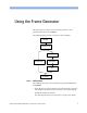
Using the Frame Generator This topic provides a short overview of what you have to do to generate frames for use in ParBERT. The following figure provides an overview of the workflow. Define files to be generated Set up pattern in GUI Generate frame file Generate frame file and segment files Edit frame file Generate segment files Import segment files into ParBERT Figure 1 SONET Workflow The following steps have to be performed to generate SONET frames for ParBERT: 1.
Using the Frame Generator Generating Frame Files 2. The settings for the frames to be generated are made on the GUI. See “How Frames are Generated” on page 13 for information about the Frame Generator. 3. The selected files are generated by selecting the File Save Menu button. This opens the Save as dialog box, where you can select the file name and path for the files to be generated. See “Generating Frame Files” on page 8 for details. 4. Import the files into ParBERT.
Importing Frames into ParBERT Using the Frame Generator Importing Frames into ParBERT When the frames have been generated, they have to be imported to ParBERT, where SONET tests can then be carried out. Editing Frame Files The Frame Generator allows one or more structured patterns (or frames) to be specified and generated. The pattern is written into a frame file and/or segment file. The segment file can be imported into the ParBERT. The following is an example of the start of an *.hfm file. #Col.
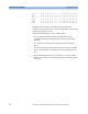
Using the Frame Generator Editing Frame Files C7.2 0 0 0 0 0 0 0 0 0 0 0 0 0 0 0 0 0 0 C7.3 0 0 0 0 0 0 0 0 0 0 0 0 0 0 0 0 0 0 #-------------------------------------------------------------------------C8.1 0 0 0 0 0 0 0 0 0 0 0 0 0 0 0 0 0 0 C8.2 0 0 0 0 0 0 0 0 0 0 0 0 0 0 0 0 0 0 C8.3 0 0 0 0 0 0 0 0 0 0 0 0 0 0 0 0 0 0 These files can be edited by any editor as text file. For better recognition of the relevant lines, each line begins with a counter with the format C..
Selecting the Files to be Generated Using the Frame Generator Selecting the Files to be Generated You can optionally select the files to be generated. By default, all files are generated. You can change this selection in a dialog box that opens when you select File -> Generation Setting. Figure 2 File generation dialog box You can select from the following files: • Frame Files (*.hfm) These files are in an human-readable intermediate format that can only be interpreted by the SONET tool.
Using the Frame Generator Converting Frame Files Converting Frame Files Once the frame files have been generated (and edited), they must be converted to segment files for use by ParBERT. This is done by the following: • Selecting File -> Convert Frame(s). • Clicking the Convert Frames button. These both open the Open dialog box, where you can select the *.htm file to be converted.
How the Frame Generator Works The following sections provide detailed specifications of the following: • How the Frame Generator generates frames This is described in the following section. • Coded Mark Inversion (CMI) coding See “CMI Coding” on page 20. • Synchronizing pattern See “Synchronizing Pattern” on page 20. How Frames are Generated The Frame Generator generates frames based on the settings made in the GUI. The following figure shows the different components of a frame.
How the Frame Generator Works How Frames are Generated See the following sections for more information: • “SONET Section Overhead and SDH RS Overhead Details” on page 18 This section describes how the section overhead is generated. • “SONET Line Overhead and SDH MS Overhead Details” on page 17 This section describes how the line overhead and multiplexer overhead are generated. • “SONET Path Overhead and SDH HP Overhead Details” on page 16 This section describes how the path overhead is generated.
How Frames are Generated How the Frame Generator Works Payload Details The payload choices are: All 1s, all 0s, alternate 1s and 0s, various PRBS options, a binary file and a pattern editor. It is important to consider the possible lengths of the PRBS with respect to the supported frame sizes. The following table shows the payload sizes generated at various rates: Table 1 Rates and payload sizes Rate Payload size STS-768 4.755.456 bits STS-192 1.188.864 bits STS-48 297.216 bits STS-12 74.
How the Frame Generator Works NO TE How Frames are Generated Please pay attention to the following when defining the payload fill. • This is a bulk fill of the payload space, not a fill of each individual payload channel.
How Frames are Generated How the Frame Generator Works G1 Path Status Byte The G1 path status byte is affected by the following alarms: • L-AIS / MS-AIS • HP-REI • L-RDI / MS-RDI Depending on which alarm is selected, the G1 path status byte is affected as follows: • No errors: 0000 0000 • AIS on: xxxx 0111 • HP-REI: 0001 0000 All Other Path Overhead All other path overhead bytes will contain 0000 0000 prior to scrambling.
How the Frame Generator Works How Frames are Generated Depending on which alarm is selected, the K2 byte is set as follows: • No errors: 0000 0000 • AIS on: 0000 0111 • RDI on: 0000 0110 For the alarm condition, no other action is taken concerning any payload or other overhead bytes, these are all unchanged from the normal (no errors) state. The K2 bytes in all other frames are unused and are set to 0000 0000. B2 Bytes General A path error monitoring function is implemented in the SONET specification.
How Frames are Generated Single B1 Error How the Frame Generator Works The user can specify a single B1 error per frame. To generate a B1 error (for channel 1 only), one 1 of a selected byte is complimented (the byte is XORed with 0000 0001). The selected byte is located at channel 1 (SONET) or channel 1-a (SDH), row 3, column 1. This byte is unused by the signal. The B1 byte itself remains unchanged. Framing A complete framing pattern (3, 12, 48, 192, 768 x F6 + 3, 12, 48, 192, 768 x 28) is generated.
How the Frame Generator Works CMI Coding CMI Coding CMI coding is a method of converting binary data into an electrical signal. Bits with the value 1 are given bipolar levels (alternating positive/negative voltages). Bits with the value 0 are represented by two voltage levels, a negative then positive level, within the same time span normally used for one digit. This type of code maintains the signal at the digital clock rate, improving signal synchronization.
Synchronizing Pattern How the Frame Generator Works When inserting a binary payload, you have to make sure that this pattern (with scrambling) is not used within the payload. The following table shows how the payload size is determined by the segment width and the different rates.
How the Frame Generator Works 22 Synchronizing Pattern Agilent 81250 ParBERT SONET/SDH Frame Generator, November 2002
Graphical User Interface Reference The Frame Generator’s Graphical User Interface (GUI) is relatively simple; the following is a short description of the GUI elements, tool bar and menus.
Graphical User Interface Reference Settings Area Settings Area NO TE Some elements of the setting area are invisible if you select CID for Mode. The invisible elements are not available for CID. The following is a list of the elements of the settings area: • Mode Defines the following modes. – Normal specifies a single frame of a SONET/SDH signal. – CID specifies a Consecutive Identical Digit pattern. • Format Defines the frame format to be generated; can either be SONET, SONET-C, or SDH.
Settings Area Graphical User Interface Reference • Rate The rate available depends on the selected Format. The following rates are available: SONET (-C) SDH STS-768 (39.81312 Gb/s) STM-256 STS-192 (9.95328 Gb/s) STM-64 STS-48 (2.48832 Gb/s) STM-16 STS-12 (622.08 Mb/s) STM-4 STS-3 (155.52 Mb/s) STM-1 • Payload This field defines how the payload is generated.
Graphical User Interface Reference Settings Area • Errors Allows you to specify errors that are to be generated in the first frame. SONET (-C) SDH S-BIP (B1) RS-BIP (B1) L-BIP (B2) MS-BIP (B2) P-BIP (B3) HP-BIP (B3) None None • Alarms Allows you to specify alarms that are to be generated in the patterns.
Menus Graphical User Interface Reference Menus The Frame Generator contains the following menus, which enable you to save files and change appearances of the application: • File menu • View menu • Help menu These are described in the following sections. File Menu The File menu contains the following elements: • Save as ... Opens the File Save dialog box, where you can select a file name and path for the frame files to be generated. See “Generating Frame Files” on page 8 for more information.
Graphical User Interface Reference Tool Bar View Menu The View menu contains the following elements: • Tool Bar Shows/hides the tool bar. • Status Bar Shows/hides the status bar. Help Menu The Help menu contains the following elements: • about_frame_gen Opens up a message box that informs you about the version number. • Help Opens the Online Help. Tool Bar The tool bar provides you quick access to most important Frame Generator functions. The following tools are available: Opens the Save as ...
Status Bar Graphical User Interface Reference Status Bar The status bar at the bottom of the GUI provides information about the status of the application. It also provides “pop-up” type tips for the menus and tools (when the mouse moves over a tool, for example, the status bar shows what the tool does).
Graphical User Interface Reference 30 Status Bar Agilent 81250 ParBERT SONET/SDH Frame Generator, November 2002
Index Index B M B1 byte 18 error 19 B2 byte 18 error 18 B3 byte 16 error 16 Menus File 27 Help 28 overview 27 View 28 O OOF (Out Of Frame) 19 BIP coding 14 P C ParBERT, importing frames 9 Path overhead 16 CMI coding 20 Pattern, synchronizing 20 F Pointer bytes 17 File generation 11 Files, overview 11 PRBS lengths 15 polynomials 15 Frame generation 13 S Frame Generator functionality 5 introduction 5 using 7 workflow 7 SDH MS overhead 17 Frames conversion 12 editing 9 generating 8 Section
Index 32 Agilent 81250 ParBERT SONET/SDH Frame Generator, November 2002