Quick Start Guide Agilent Technologies Models 6811B - 6814B, 6834B, and 6843A AC Power Solutions Documentation Map Quick Start Guide (this document) Condensed overview of ac source operation. Read this to quickly get started. Quick Reference Card Memory jogger for front panel and remote programming commands. Use this if you are already familiar with programming the ac source.
Contents The front panel, at a glance 3 The rear panel, at glance 4 What the ac source can do 5 How to use the front panel 7 Some basic operations 9 Measuring the output 11 Programming output transients 13 Programming trigger synchronization and delays 15 The front panel menus, at a glance 17 Agilent sales and Support Offices 20 Safety Notice The beginning of the User’s Guide has a Safety Summary page for this instrument. Familiarize yourself with the contents of that page.
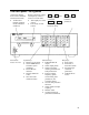
The front panel - at a glance 14-character display shows menu commands and measured values. ♦ Annunciators indicate operating modes and status conditions. Turns the ac source on or off Rotary controls set voltage and frequency when ac source is in local mode. ♦ Turn rapidly for coarse control ♦ Turn slowly for fine control.
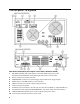
The rear panel - at a glance Rear Panel Connections (see Chapter 3 in the User’s Guide for details) 1 INH (Remote Inhibit) TTL input signal for externally disabling the power source. FLT (Discrete Fault Indicator) TTL output signal when there is a device fault. 2 RS-232 connector for remote controller. 3 TRIGGER BNC connectors for external trigger inputs and &source; trigger outputs. 4 GPIB connector and GPIB cable for remote controller. 5 SENSE connections for remote voltage sensing at the load.
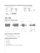
What the ac source can do Generate waveform shapes ♦ Sinewave ♦ Squarewave ♦ Clipped sinewave ♦ User-definable waveforms Program the output ♦ Phase Agilent Models 6811B, 6812B, 6813B program the following additional output functions: ♦ Ac rms voltage ♦ Dc voltage ♦ Distortion ♦ Peak Current limit ♦ Frequency ♦ AC coupling ♦ Voltage and frequency slew rates ♦ Impedance ♦ Rms current limit Make the following measurements Agilent Models 6811B, 6812B, 6813B make the following additi
Synchronize transient events or measurements with external signals ♦ ♦ Triggers applied to the unit Triggers generated by the unit Operate in four transient modes ♦ Fixed ♦ Step ♦ Pulse Operate under local or remote control ♦ From the front panel keys ♦ Through the built-in GPIB or RS-232 interfaces Implement protection features ♦ Over-voltage ♦ Over-current ♦ Over-power ♦ Over-temperature ♦ User-defined external events (via a FLT shutdown signal) 6 ♦ List
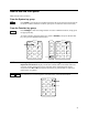
How to use the front panel Make sure the unit is turned on. From the System key group Local Press Local to activate the front panel keypad if the unit is not already in local mode. (If the Local Lockout command is in effect, cycle power to return the unit to local mode.) From the Function key group Press Voltage to select the voltage function. To select a different function, simply press the appropriate key.
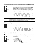
The following chart shows the commands in the Voltage function menu. Some commands may not appear on all models. Menus are circular, you can return to the starting position by continuously pressing p or q.
Some basic operations Make sure the unit is turned on. Use either the front panel keys or the corresponding SCPI commands. The column on the left indicates the front panel keys that program the indicated action. If the SCPI programming syntax is substantially different from the front panel menu command, it is shown inside parentheses ( ). The text to the right describes the result. If appropriate, the resultant output waveshape is shown underneath the description.
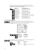
Set the rms current limit (and peak current on Agilent 6811B/6812B/6813B units) When this command is sent, the rms current limit is set to 10 A. If more current than the programmed limit is drawn, the output voltage amplitude is reduced to keep the rms current within the specified limit. Press Shift Current and q to access CURR:PEAK, which lets you set the peak current limit on Agilent 6811B/6812B/6813B units.
Measuring the output All measurements are based on acquiring and subsequently processing output waveform information. When the ac source is on, it takes measurements and updates the front panel meter continuously. The Meter key accesses the measurement functions from the front panel. The SCPI MEASure command acquires new waveform information each time it is executed. The SCPI FETCh command does not acquire new waveform information but extracts the desired information from previously acquired waveform data.
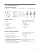
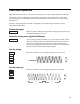
Harmonic measurements Use the harmonic menu to make harmonic measurements of the output current. The following example illustrates the current magnitude measurements returned at harmonics 0 to 5. Note that harmonic 1 is the fundamental. Harmonic 0 is the dc component. Shift Harmonic 0.01A I:MAG:0 current amplitude at harmonic 0 (FETC/MEAS) Shift pIndex 1.43A I:MAG:1 current amplitude at harmonic 1 Shift pIndex 0.01A I:MAG:2 current amplitude at harmonic 2 Shift pIndex 0.
Programming output transients Up to now the ac source has been programmed with the transient system in Fixed mode. The following examples briefly describe the transient system’s Step, Pulse, and List modes, which require the application of a trigger to implement the transient mode. NOTE: For the examples that follow, press Shift Output, scroll to *RST and press Enter to reset the unit prior to each example. Also press Enter to enter or activate each selection.
More transient examples The previous examples showed how the transient system can be used to control the output voltage amplitude. The transient system can also control output frequency, phase, waveform shape, voltage and frequency slew rates, offset voltage, and peak current limit. The following examples illustrate how the transient system’s Pulse mode can generate frequency, shape, phase, and voltage slew pulses. Freq FREQ TRIG FREQ:M PULSE FREQ 60 FREQ:T 50 FREQ Pulse width WIDTH .
Programming trigger synchronization and delays The previous transient examples were programmed to respond to immediate triggers. However, delayed and phase synchronized triggers can also be programmed as shown in the following examples. No delay; no phase synchronization Voltage VOLT:M STEP VOLT 120 VOLT:T 150 Trigger Control When these commands are sent, the voltage amplitude changes immediately upon the receipt of a trigger.
Trigger delay; 90 degree phase synchronization Voltage VOLT:M STEP VOLT 120 VOLT:T 150 When these commands are sent, the voltage amplitude changes at the next 90 degree phase angle that occurs after the .0167 second delay has expired, following the receipt of a trigger. 0 Trigger Control 90 TRIG level DELAY .
The front panel menus - at a glance FUNCTION Keys SYSTEM Keys Local Press to change the ac source’s selected interface from remote operation to local (front panel) operation. Pressing the key will have no effect if the interface state is already Local, Localwith-Lockout, or Remote-with-Lockout. Error Address Error Functions Displays system error codes stored in the SCPI error queue. If no errors exist, a 0 is displayed. The Err annunciator is lit when there are errors.
Trigger Trigger Control Trigger Function Pressing the Shift Trigger key generates an immediate trigger Trigger Control Functions INIT:IMMED Initiate trigger immediately INIT:CONT ON | OFF Initiate trigger continuously Select transient trigger source TRIG:SOUR BUS | EXT TTLT | IMM DELAY Set trigger delay in seconds ABORT Abort all trigger sequences SYNC:SOUR PHASE | IMM Select synchronous trigger source SYNC:PHASE Set synchronous phase reference Current Voltage Current Functions CURR:LEV
ENTRY Keys ¯ ° These keys let you scroll through choices in a parameter list that apply to a specific command. Parameter lists are circular; you can return to the starting position by continuously pressing either key. If the command has a numeric range, these keys increment or decrement the existing value. 0 − − . Enter E 0 Clear Entry Calibration 7 9 The numeric keys 0 through 9 are used for entering numeric values. Press shift and this key to enter a minus.
Agilent Sales and Support Offices For more information about Agilent Technologies test and measurement products, applications, services, and for a current sales office listing, visit our web site: http://www.agilent.com/find/tmdir You can also contact one of the following centers and ask for a test and measurement sales representative. United States: Agilent Technologies Test and Measurement Call Center P.O.