Agilent U1251A and U1252A Handheld Digital Multimeter User’s and Service Guide Agilent Technologies
Notices © Agilent Technologies, Inc. 2006 – 2012 Warranty No part of this manual may be reproduced in any form or by any means (including electronic storage and retrieval or translation into a foreign language) without prior agreement and written consent from Agilent Technologies, Inc. as governed by United States and international copyright laws. The material contained in this document is provided “as is,” and is subject to being changed, without notice, in future editions.
Safety Symbols The following symbols on the instrument and in the documentation indicate precautions which must be taken to maintain safe operation of the instrument.
Safety Information This meter is safety-certified in compliance with EN/IEC 61010-1:2001, UL 61010-1 Second Edition and CAN/CSA 22.2 61010-1 Second Edition, CAT III 1000 V/ CAT IV 600 V Overvoltage Protection, Pollution Degree II. Use with standard or compatible test probes. General Safety Information The following general safety precautions must be observed during all phases of operation, service, and repair of this instrument.
WA R N I N G • When working above 70 VDC, 33 VAC RMS or 46.7 V peak, exercise caution – such range pose a shock hazard. • Do not measure more than the rated voltage (as marked on the meter) between terminals, or between terminal and earth ground. • Double-check the meter’s operation by measuring a known voltage. • For current measurement, turn off circuit power before connecting the meter to the circuit. Always place the meter in series with the circuit.
CAUTION VI • Turn off the circuit power and discharge all high-voltage capacitors in the circuit before you perform resistance, continuity, diodes, or capacitance tests. • Use the correct terminals, function, and range for your measurements. • Never measure voltage when current measurement is selected. • Use only recommended rechargeable battery. Ensure proper insertion of battery in the meter, and follow the correct polarity. • Disconnect test leads from all the terminals during battery charging.
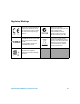
Regulatory Markings The CE mark is a registered trademark of the European Community. This CE mark shows that the product complies with all the relevant European Legal Directives. The C-tick mark is a registered trademark of the Spectrum Management Agency of Australia. This signifies compliance with the Australia EMC Framework regulations under the terms of the Radio Communication Act of 1992. ICES/NMB-001 indicates that this ISM device complies with the Canadian ICES-001.
Waste Electrical and Electronic Equipment (WEEE) Directive 2002/96/EC This instrument complies with the WEEE Directive (2002/96/EC) marking requirement. This affixed product label indicates that you must not discard this electrical/electronic product in domestic household waste. Product Category: With reference to the equipment types in the WEEE directive Annex 1, this instrument is classified as a “Monitoring and Control Instrument” product. The affixed product label is as shown below.
In This Guide… 1 Getting Started This chapter contains information on the Agilent U1251A and U1252A handheld multimeter front panel, rotary switch, keypad, display, terminals and rear panel. 2 Making Measurements This chapter contains information on how to make measurements using the U1251A and U1252A handheld digital multimeter. 3 Functions and Features This chapter contains information on the functions and features that are available for the U1251A and U1252A digital multimeter.
Declaration of Conformity (DoC) The Declaration of Conformity (DoC) for this instrument is available on the Web site. You can search the DoC by its product model or description. http://regulations.corporate.agilent.com/DoC/search.htm NOTE If you are unable to search for the respective DoC, please contact your local Agilent representative.
III Contents 1 Getting Started Introducing the U12521A/U1252A Handheld Digital Multimeter Check the shipment 2 3 Adjusting the tilt-stand 4 The rear panel at a glance 7 The keypad at a glance 9 The display at a glance 11 Selecting display with the Hz button 16 Selecting display with the Dual button 18 Selection display with the Shift button 20 The terminals at a glance 22 2 Making Measurements Understanding The Measurement Instructions Measuring Voltage 24 Measuring AC voltage Measuring DC voltage 2
III Overload alert 47 Input warning 47 Charge terminal alert 3 48 Functions and Features Dynamic Recording 50 Data Hold (Trigger Hold) Refresh Hold Null (Relative) 52 53 55 Decibel Display 57 1 ms Peak Hold 59 Data Logging 61 Manual logging 61 Interval logging 63 Reviewing logged data 65 Square Wave Output (for U1252A) Remote Communication 4 67 71 Changing The Default Setting Selecting Setup Mode 74 Setting Data Hold/Refresh Hold Mode Setting Data Logging Mode 77 78 Setting Thermocou
III Setting Beep Frequency Setting Backlight Timer Setting Baud Rate 89 Setting Parity Check Setting Data Bit 87 88 90 91 Setting Echo Mode 92 Setting Print Mode 93 Returning to Default Factory Settings 5 94 Maintenance Introduction 96 General maintenance 96 Battery replacement 96 Storage considerations 98 Charging the battery 98 Fuse checking procedure 105 Replacing the fuse 106 Troubleshooting 108 Replaceable Parts 109 To order replaceable parts 6 109 Performance Tests and Calibration Calib
III Testing the display 115 Current terminal test 116 Charge terminal alert test 117 Test Considerations 118 Calibration Security 119 Performance Verification Tests 120 Unsecuring the instrument for calibration Calibration process 131 Using the front panel for adjustments 128 132 Adjustments Consideration 133 Valid adjustment input values 134 Adjustment procedure 135 Finishing the adjustment 142 To read the calibration count 142 Calibration errors 143 7 Specifications Product Characteristics 146
III Peak Hold Specifications 159 Frequency Counter Specifications for U1252A Square Wave Output for U1252A 161 Operating Specifications 162 Display update rate (approximate) Input impedance 163 Abbreviated Book Title Variable (Edit this) 160 162 XVII
III XVIII Abbreviated Book Title Variable (Edit this)
List of Figures Figure 1-1 Figure 1-2 Figure 1-3 Figure 1-4 Figure 1-5 Figure 1-6 Figure 1-7 Figure 1-8 Figure 1-9 Figure 2-1 Figure 2-2 Figure 2-3 Figure 2-4 Figure 2-5 Figure 2-6 Figure 2-7 Figure 2-8 Figure 2-9 Figure 2-10 Figure 2-11 Figure 2-12 Figure 2-13 Figure 2-14 Figure 2-15 Figure 2-16 Figure 2-17 Figure 3-1 Figure 3-2 Figure 3-3 Figure 3-4 Figure 3-5 Figure 3-6 Figure 3-7 Abbreviated Book Title Variable (Edit this) Tilt-stand at 60° 4 Tilt-stand at 30° 4 Tilt-stand at hanging position 5 U1252A
Figure 3-8 Figure 3-9 Figure 3-10 Figure 3-11 Figure 3-12 Figure 3-13 Figure 3-14 Figure 4-1 Figure 4-2 Figure 4-3 Figure 4-4 Figure 4-5 Figure 4-6 Figure 4-7 Figure 4-8 Figure 4-9 Figure 4-10 Figure 4-11 Figure 4-12 Figure 4-13 Figure 4-14 Figure 4-15 Figure 4-16 Figure 5-1 Figure 5-2 Figure 5-3 Figure 5-4 Figure 5-5 Figure 5-6 Figure 5-7 Figure 6-1 Figure 6-2 Figure 6-3 X Full Log 62 Interval (Automatic) logging mode operation 64 Log review mode operation 66 Frequency adjustment for square wave output 6
II List of Tables Table 1-1 Table 1-2 Table 1-3 Table 1-4 Table 1-5 Table 1-6 Table 1-7 Table 1-8 Table 1-9 Table 1-10 Table 2-1 Table 2-2 Table 2-3 Table 4-1 Table 5-1 Table 5-2 Table 5-3 Table 5-4 Table 5-5 Table 6-1 Table 6-2 Table 6-3 Table 6-4 Table 7-1 Table 7-2 Table 7-3 Table 7-4 Table 7-5 Table 7-6 Abbreviated Book Title Variable (Edit this) Rotary switch description and functions 8 Keypad desciption and functions 9 General display symbols 12 Priamry display symbols 13 Secondary display symbols
II Table 7-7 Table 7-8 Table 7-9 Table 7-10 Table 7-11 Table 7-12 Table 7-13 Table 7-14 Table 7-15 Table 7-16 Table 7-17 Table 7-18 Table 7-19 XII U1252A true RMS ac+dc current specifications 155 Capacitance specifications 156 Temperature specifications 156 Frequency specifications 157 Duty cycle and pulse width specifications 157 Frequency sensitivity and trigger level specifications for voltage measurements 158 Frequency sensitivity specifications for current measurements 159 Peak hold specifications f
Agilent U1251A and U1252A Handheld Digital Multimeter User’s and Service Guide 1 Getting Started Introducing the U12521A/U1252A Handheld Digital Multimeter 2 Check the shipment 3 Adjusting the tilt-stand 4 The front panel at a glance 6 The rear panel at a glance 7 The rotary switch at a glance 8 The keypad at a glance 9 The display at a glance 11 Selecting display with the Hz button 16 Selecting display with the Dual button 18 Selection display with the Shift button 20 The terminals at a glance 22 This ch
1 Getting Started Tutorial Introducing the U12521A/U1252A Handheld Digital Multimeter Key features of this digital multimeter: • DC, AC, and AC + DC (U1252A only) voltage and current measurements.
Getting Started Tutorial 1 Check the shipment Verify that you have received the following items with your multimeter: • 9 V alkaline battery (for U1251A only) • Soft carrying case • 4 mm probes • Test leads • Alligator clips • SMT grabbers • Fine tips test probes • Mini grabber (black only) • Rechargeable 7.
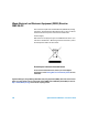
1 Getting Started Tutorial Adjusting the tilt-stand To adjust the meter to a 60° standing position, pull the tilt- stand outwards to its maximum reach. IR-USB cable To PC (host) Tilt-stand at 60 ° Figure 1-1 Tilt-stand at 60° To adjust the meter to a 30° standing position, bend the tip of the stand so that it is parallel to the ground before pulling the stand outwards to its maximum reach.
Getting Started Tutorial 1 To adjust the meter to a hanging position follow the steps shown in Figure 1- 3 below. 1. Extend the tilt-stand until its maximum reach 2. Detach the tilt-stand 4. Re-attach the tilt-stand to an upright position 3. Flip the tilt-stand over until this side of the stand is facing the device instead of facing you.
1 Getting Started Tutorial The front panel at a glance Display Keypad Rotary switch Terminal Connectors Figure 1-4 U1252A front panel 6 Agilent U1251A/U1252A User’s and Service Guide
Getting Started Tutorial 1 The rear panel at a glance IR communication port Test probe holders Tilt-stand Battery access cover Figure 1-5 Rear panel Agilent U1251A/U1252A User’s and Service Guide 7
1 Getting Started Tutorial The rotary switch at a glance 6 7 8 5 4 3 2 9 1 10 Figure 1-6 Rotary switch Table 1-1 Rotary switch description and functions No.
Getting Started Tutorial 1 The keypad at a glance The operation of each key is shown below. Pressing a key illuminates a related symbol on the display and emits a beep from the multimeter. Turning the rotary switch to another position resets the current operation of the key. Figure 1- 7 below shows the keypad of the U1252A. The ms% (Pulse width/Duty cycle), Hz , and frequency counter functions are only available on the U1252A.
1 Getting Started Tutorial Button 4 Function when pressed for less than 1 second Function when pressed for more than 1 second scrolls through the measuring function(s) at a enters Log Review mode. Press to particular rotary switch position. switch to manual or interval logging data. Press or to view first or last logged data respectively. Press or to scroll up or down logged data. Press for more than 1 second to exit mode.
Getting Started Tutorial 1 The display at a glance To view the full display (with all segments illuminated), press and hold the button while turning the rotary switch from OFF to any non- OFF position. After you have finished viewing the full display, press any button to resume normal functionality based on the rotary switch position. This is followed by a wake- up feature. The meter will then enter power save mode once auto power off (APF) is enabled.
1 Getting Started Tutorial Table 1-3 General display symbols LCD symbol Description Remote control Thermocouple types: NULL (K-type) (J-type) Null math function Diode / Audible continuity Audible continuity for resistance View mode for checking logged data Data logging indication Square wave output (U1252A only) • Positive slope for pulse width (ms) and duty cycle (%) measurement • Charging capacitor as capacitance measurement • Negative slope for pulse width (ms) and duty cycle (%) measurement
Getting Started Tutorial 1 The primary display signs are explained below.
1 Getting Started Tutorial The secondary display signs are explained below.
Getting Started Tutorial 1 The “+” or “–” sign is indicated when the positive or negative value has been measured or calculated. Each segment represents 2500 or 500 counts depending on the range indicated on the peak bar graph. See the Table 1- 6 below.
1 Getting Started Tutorial Selecting display with the Hz button The frequency measurement feature helps to detect the presence of harmonic currents in neutral conductors and determines whether these neutral currents are the result of unbalanced phases or non- linear loads. Press to access the frequency measurement mode for current or voltage measurements — voltage or current on the secondary display and frequency on the primary display.
Getting Started Tutorial 1 Table 1-7 Selecting display with the Hz button (continued) Frequency (Hz) (AC + DC voltage) [for U1252A] Pulse width (ms) Duty cycle (%) Frequency (Hz) (AC Current) AC µA Pulse width (ms) Duty cycle (%) Frequency (Hz) (DC current) AC + DC mV DC µA Pulse width (ms) Duty cycle (%) (AC + DC current) [for U1252A] (AC current) (DC current) Frequency (Hz) Pulse width (ms) Duty cycle (%) Frequency (Hz) Pulse width (ms) Hz (Frequency counter) - press to select frequency div
1 Getting Started Tutorial Selecting display with the Dual button Press to select different combinations of dual display. Normal single display resumes after you press and hold for more than 1 second. See Table 1- 8 below.
Getting Started Tutorial 1 Table 1-8 Selecting display with the Dual button (AC + DC voltage) (DC current) (AC current) (AC + DC current) [for U1252A] (DC current) (AC current) (AC + DC current) [for U1252A] AC + DC mV dBm or dBV AC + DC mV AC + DC mV AC + DC mV Hz (AC coupling) AC + DC mV AC mV DC mV Ambient temperature °C or °F Hz (DC coupling) DC μA DC μA DC μA AC μA AC μA AC μA AC + DC μA AC + DC μA AC + DC μA AC + DC μA DC mA DC mA % (0–20 or 4–20) DC mA AC mA AC mA AC mA AC + DC mA AC + DC
1 Getting Started Tutorial Table 1-8 Selecting display with the Dual button (AC + DC current) [for U1252A] (Capacitance) AC + DC A AC + DC A AC + DC A AC + DC A nF / V / Ω / nS Hz (AC coupling) AC A DC A Ambient temperature °C or °F Ambient temperature °C or °F °C (°F) °C (°F) Ambient temperature °C or °F Ambient temperature °C or °F / 0 °C compensation (select by pressing ) (Diode)/ Ω (Resistance)/ nS (Conductance) TEMP (Temperature) Notes for selecting display with the Dual button: 1 Reading of d
Getting Started Tutorial 1 Table 1-9 Selecting display with the Shift button DC mV AC mV AC + DC mV for U1252A (AC + DC Voltage) Ω Ω Ω (Resistance) nS Diode Hz (Diode Test and Frequency) Capacitance Temperature / TEMP (Capacitance and Temperature) DC μA AC μA (AC Current) AC + DC μA [for U1252A] (DC Current) DC mA AC mA AC + DC mA %(0–20 or 4–20) DC A AC A AC + DC A [for U1252A] (AC + DC Current) Duty cycle (%) Pulse width (ms) (Square wave output for U1252A) Notes for selecting display with
1 Getting Started Tutorial The terminals at a glance WA R N I N G To avoid damaging the multimeter, do not exceed the input limit. Figure 1-9 U1252A connector terminals Table 1-10 Terminal connections for different measuring functions Rotary switch position Input terminals V . mV . Ω . Overload protection COM 1000 V R.M.S. for U1252A V for U1251A .TEMP 1000 V R.M.S. for short circuit <0.3 A Ω for U1252A μA .
Agilent U1251A and U1252A Handheld Digital Multimeter User’s and Service Guide 2 Making Measurements Understanding The Measurement Instructions 24 Measuring Voltage 24 Measuring AC voltage 25 Measuring DC voltage 26 Measuring Current 27 µA & mA measurement 27 Percentage scale of 4 mA to 20 mA 29 A (ampere) measurement 31 Frequency Counter 32 Measuring Resistance, Conductance and Testing Continuity 34 Testing Diodes 38 Measuring Capacitance 41 Measuring Temperature 43 Alerts and Warning During Measurement 4
2 Making Measurements Understanding The Measurement Instructions When making measurements, follow the numerical steps labelled in the diagrams. Refer to Table 2- 1 below for a description of the steps. Table 2-1 Numerical steps descriptions No.
Making Measurements 2 Measuring AC voltage Set up the multimeter to measure AC voltage as shown in Figure 2- 1. Probe the test points and read the display. Red Lead Black Lead Figure 2-1 Measuring AC voltage NOTE Press to display frequency on secondary display. See Table 1-8 of “Selecting display with the Dual button” on page 18 for a list of the different combinations available on the secondary display.
2 Making Measurements Measuring DC voltage Set up the multimeter to measure DC voltage as shown in Figure 2- 2. Probe the test points and read the display.
Making Measurements 2 Measuring Current µA & mA measurement Set up the multimeter to measure μA & mA as shown in Figure 2- 3. Probe the test points and read the display. NOTE • Press if necessary to ensure is shown on the display. • For μA measurement, set the rotary switch to the positive test lead to μA.mA. and connect • For mA measurement, set the rotary switch to connect the positive test lead to μA.mA.
2 Making Measurements Black Lead Red Lead Figure 2-3 Measuring μA and mA current 28 Agilent U1251A/U1252A User’s and Service Guide
Making Measurements 2 Percentage scale of 4 mA to 20 mA Set up the multimeter to measure percentage scale as shown in Figure 2- 4. Probe the test points and read the display. NOTE • Press to select percentage scale display. Ensure that is shown on the display. or • The percentage scale for 4 mA to 20 mA or 0 mA to 20 mA is calculated using its corresponding DC mA measurement. The U1251A/U1252A will automatically optimize the best resolution according to Table 2-2 below.
2 Making Measurements Black Lead Red Lead Figure 2-4 Measuring scale of 4-20 mA 30 Agilent U1251A/U1252A User’s and Service Guide
Making Measurements 2 A (ampere) measurement Set up the multimeter to measure A (ampere) as shown in Figure 2- 5. Probe the test points and read the display. NOTE Connect the red and black test leads to the 10 A input terminal A and COM respectively. The meter is set to A measurement automatically when the red test lead is plugged into the A terminal.
2 Making Measurements Frequency Counter WA R N I N G • Use the frequency counter for low voltage applications only. Never use the frequency counter for line power system. • For inputs more than 30 Vpp, you are required to use frequency measurement mode available under the current or voltage measurement instead of frequency counter. Set up the multimeter to measure frequency as shown in Figure 2- 6. Probe the test points and read the display. NOTE • Press to select the Frequency counter (Hz) function.
Making Measurements 2 Hz Black Lead Red Lead Figure 2-6 Measuring frequency Agilent U1251A/U1252A User’s and Service Guide 33
2 Making Measurements Measuring Resistance, Conductance and Testing Continuity CAUTION Disconnect the circuit power and discharge all high-voltage capacitors before measuring the resistance to prevent any possible damage to the multimeter or the device under test. Set up the multimeter to measure resistance as shown in Figure 2- 7. Then probe the test points (by shunting the resistor) and read the display.
Making Measurements 2 Press to scroll through audible continuity, conductance and resistance tests as shown in Table 2- 8. Press SHIFT Audible continuity Press MAX Press SHIFT Figure 2-8 Audible continuity, conductance, and resistance test.
2 Making Measurements Audible continuity In the range of 0–500 Ω, the beeper will sound if the resistance value falls below 10 Ω. For other ranges, the beeper will sound if the resistance falls below the typical values indicated in Table 2- 3 below. Table 2-3 Audible continuity measurement range Measurement range Beeper sound threshold 500.00 Ω < 10 Ω 5.0000 kΩ < 100 Ω 50.000 kΩ < 1 kΩ 500.00 kΩ < 10 kΩ 5.0000 MΩ < 100 kΩ 50.000 MΩ < 1 MΩ 500.
Making Measurements 2 nS Ω MAX Black Lead Red Lead Figure 2-9 Conductance measurement Agilent U1251A/U1252A User’s and Service Guide 37
2 Making Measurements Testing Diodes CAUTION Disconnect the circuit power and discharge all the high-voltage capacitors before testing the diodes to prevent any possible damage to the meter. To test a diode, turn the power off to the circuit and remove the diode from the circuit. Set up the multimeter as shown in Figure 2- 10, then use the red probe lead on the positive terminal (anode) and use the black probe lead on the negative terminal (cathode) and read the display.
Making Measurements 2 Hz Black Lead Red Lead Figure 2-10 Measuring forward bias of diode Agilent U1251A/U1252A User’s and Service Guide 39
2 Making Measurements Hz Black Lead Red Lead Figure 2-11 Measuring reverse bias of diode 40 Agilent U1251A/U1252A User’s and Service Guide
Making Measurements 2 Measuring Capacitance CAUTION Disconnect the circuit power and discharge all the high-voltage capacitors before measuring the capacitance to prevent any possible damage to the meter or the device under test. To confirm that the capacitors have discharged, use the DC voltage function. The meter measures capacitance by charging the capacitor with a known current for a period of time, measuring the voltage and then calculating the capacitance.
2 Making Measurements TEMP Red Lead Black Lead Figure 2-12 Capacitance measurements 42 Agilent U1251A/U1252A User’s and Service Guide
Making Measurements 2 Measuring Temperature CAUTION Do not bend the thermocouple leads at sharp angles. Repeated bending over a period of time may break the leads. The bead type thermocouple probe is suitable for making temperature measurements between –20 °C to 200 °C in PTFE compatible environments. Do not use the bead- type thermocouple probe beyond the recommended operating temperature range. Do not immerse this thermocouple probe in liquids.
2 Making Measurements 8 For a quick measurement, use the 0 °C compensation adapter to see the temperature variation of the thermocouple sensor. The 0 °C compensation adapter assists in measuring the relative temperature immediately.
Making Measurements 2 If you are working in a constantly varying environment, where ambient temperatures are not constant, do the following: 1 Press to select 0 °C compensation. This gives a quick measurement of the relative temperature. 2 Avoid contact between the thermocouple probe and the measurement surface. 3 After a constant reading is obtained, press to set the reading as the relative reference temperature. 4 Touch the measurement surface with the thermocouple probe.
2 Making Measurements TEMP Figure 2-15 Surface temperature measurement 46 Agilent U1251A/U1252A User’s and Service Guide
Making Measurements 2 Alerts and Warning During Measurement Overload alert WA R N I N G For your safety, look out for this alert. When you are alerted, immediately remove the test leads from the measuring source. The meter provides an overload alert for voltage measurements in both auto and manual range modes. The meter beeps periodically once the measuring voltage exceeds 1010 V. For your safety, please be aware of this alert.
2 Making Measurements Charge terminal alert The meter sounds an alert beep when the terminal detects a voltage level of more than 5 V and the rotary switch is not set to the corresponding location. The primary display indicates a flashing “Ch.Err” until the lead is removed from the input terminal. Refer to Figure 2- 17 below.
Agilent U1251A and U1252A Handheld Digital Multimeter User’s and Service Guide 3 Functions and Features Dynamic Recording 50 Data Hold (Trigger Hold) 52 Refresh Hold 53 Null (Relative) 55 Decibel Display 57 1 ms Peak Hold 59 Data Logging 61 Manual logging 61 Interval logging 63 Reviewing logged data 65 Square Wave Output (for U1252A) 67 Remote Communication 71 This chapter contains information on the functions and features that are available for the U1251A and U1252A digital multimeter.
3 Features and Functions Dynamic Recording The Dynamic Recording mode can be used to detect intermittent turn- on or turn- off voltage, current surges or to verify measurement performance without you being present during the process. While the readings are being recorded, you are free to perform other tasks. The average reading is useful for smoothing out unstable inputs, estimating the percentage of time a circuit is operating and verifying circuit performance.
Features and Functions Press Max Min for > 1 sec 3 Press Max Min Press Max Min for > 1 sec or press for > 1 sec Press Max Min Press Max Min for > 1 sec or press for > 1 sec Press Max Min Press Max Min for > 1 sec or press for > 1 sec Figure 3-1 Dynamic recording mode operation Agilent U1251A/U1252A User’s and Service Guide 51
3 Features and Functions Data Hold (Trigger Hold) The data hold function allows the user to freeze the displayed digital value. 1 Press to freeze the displayed value and to enter the manual trigger mode. TRIG is displayed. 2 Press again to freeze the next value being measured. TRIG flashes before the new value is updated on the display. 3 Press and hold or quit the data hold function.
Features and Functions 3 Refresh Hold The Refresh Hold function allows you to freeze the displayed value. The bar- graph is not held and will continue to reflect the instantaneous measured value. You can use the Setup mode to enable Refresh Hold mode when you are working with fluctuating values. This function will auto trigger or update the held value with a new measured value and emit a tone as a reminder. 1 Press to enter Refresh Hold mode. The present value will be held and the symbol will appear.
3 Features and Functions Press Variation counts > setting The HOLD sign flashes until the measured value is stable and updated Measurement is updated Press to return Figure 3-3 Refresh hold mode operation NOTE • For voltage and current measurements, the holding value will not be updated if the reading is below 500 counts. • For resistance and diode measurements, the holding value will not be updated if the reading is in “OL” (open state).
Features and Functions 3 Null (Relative) The Null function subtracts a stored value from the present measurement and displays the difference between the two. 1 Press to store the displayed reading as the reference value to be subtracted from subsequent measurements and to set the display to zero. NULL is displayed. 2 Press to see the stored reference value. NULL flashes for 3 seconds before the display returns to zero. 3 To exit this mode, press the display.
3 Features and Functions Press Press Press Figure 3-4 Null (relative) mode operation 56 Agilent U1251A/U1252A User’s and Service Guide
Features and Functions 3 Decibel Display The dBm operation calculates the power delivered to a reference resistance relative to 1 mW and can be applied to DC V, AC V, and AC + DC V measurements for decibel conversion. The voltage measurement is converted to dBm by using the following formula: The reference resistance may be selected from 1~9999 Ω in Setup mode. The default value is 50 Ω. The decibel of voltage is calculated with respect to 1 V.
3 Features and Functions Press Press Press Press Press Press Press Press Press Press Figure 3-5 dBm/dBV display mode operation 58 Agilent U1251A/U1252A User’s and Service Guide
Features and Functions 3 1 ms Peak Hold The Peak Hold function allows the measurement of peak voltage for analysis of components such as power distribution transformers and power factor correction capacitors. The peak voltage obtained can be used to determine the crest factor: Crest factor = Peak value/True RMS value 1 Press for more than 1 second to toggle 1 ms Peak Hold mode ON / OFF. 2 Press to scroll through maximum and minimum peak readings.
3 Features and Functions Press Press Press Press Press Press Figure 3-6 1 ms peak hold mode operation 60 Agilent U1251A/U1252A User’s and Service Guide
Features and Functions 3 Data Logging The data logging function provides the convenience of recording test data for future review or analysis. Since data is stored in nonvolatile memory, the data remains saved even if the multimeter is turned OFF or the battery is changed. The two options offered are manual (hand) logging and interval (time) logging functions, which is determined in the Setup mode. Data logging records the values on the primary display only.
3 Features and Functions Press Press Figure 3-7 Hand (Manual) logging mode operation NOTE The maximum data that can be stored is 100 entries. When the 100 entries are filled, the secondary display indicates “FULL”, as shown in Figure 3-8.
Features and Functions 3 Interval logging Firstly, ensure that interval (time) logging is specified in Setup mode. 1 Press for more than 1 second to store the present value and function on the primary display into the non- volatile memory. The and the logging index will be indicated. The readings are automatically saved into the permanent memory at intervals set using the Setup mode. NOTE The maximum data that can be stored is 200 entries.
3 Features and Functions Press Press Press Figure 3-9 Interval (Automatic) logging mode operation 64 Agilent U1251A/U1252A User’s and Service Guide
Features and Functions 3 Reviewing logged data 1 Press for more than 1 second to enter the Log Review mode. The last recorded entry and the last logging index are displayed. 2 Press to switch between hand (manual) and interval (automatic) logging review mode. 3 Press to ascend or to descend through the logged data. Press to select the first record and press to select the last record for quick navigation. 4 Press for more than 1 second at the respective Log Review mode to clear logged data.
3 Features and Functions Press Press Press Press Press Press Press Press Press Press Press Press Press Press Press Press Press Press Press Figure 3-10 Log review mode operation 66 Agilent U1251A/U1252A User’s and Service Guide
Features and Functions 3 Square Wave Output (for U1252A) The square wave output function can be used to generate a PWM (pulse width modulation) output or provide a synchronous clock source (baud rate generator). You can also use this function to check and calibrate flow- meter displays, counters, tachometers, oscilloscopes, frequency converters, frequency transmitters, and other frequency input devices. Press 1 Turn the rotary switch to position.
3 Features and Functions Figure 3-11 Frequency adjustment for square wave output 5 Press display. to select the pulse width (ms) on the primary 6 Press or to adjust the pulse width. The pulse width can be set for 256 steps and each step is 1/ (256 x Frequency). The display range automatically adjusts in the range of 9.9999~9999.9 ms.
Features and Functions 3 Press Press Press Press Press Press Press Press Figure 3-12 Pulse width adjustment for square wave output Agilent U1251A/U1252A User’s and Service Guide 69
3 Features and Functions Figure 3-13 Duty cycle adjustment for Square Wave 70 Agilent U1251A/U1252A User’s and Service Guide
Features and Functions 3 Remote Communication The meter has a bi- directional (full duplex) communication capability that speeds data storing from the meter to the PC. To use this feature, you are required to use the optional IR- USB cable with the application software included in the CD or downloadable from the Agilent Web site.
3 72 Features and Functions Agilent U1251A/U1252A User’s and Service Guide
Agilent U1251A and U1252A Handheld Digital Multimeter User’s and Service Guide 4 Changing The Default Setting Selecting Setup Mode 74 Setting Data Logging Mode 78 Setting Thermocouple Types (U1252A only) 79 Setting Reference Impedance for dBm Measurement 80 Setting Minimum Frequency Measurement 81 Setting Temperature Unit 82 Setting Auto Power Saving Mode 84 Setting Percentage (%) Scale Readout 86 Setting Beep Frequency 87 Setting Backlight Timer 88 Setting Baud Rate 89 Setting Parity Check 90 Setting Data
4 Changing The Default Setting Selecting Setup Mode To enter the Setup mode, perform the following steps: 1 Turn the meter OFF. 2 From the OFF position, press and hold while turning the rotary switch to any non- OFF position. NOTE When you hear a beep, the meter is in Setup mode and you can release To change a menu item setting in Setup mode, perform the following steps: 1 Press or to scroll through the menu items. 2 Press or to scroll through the available settings.
Changing The Default Setting 4 Table 4-1 Available setting options in Setup mode Menu Item Display Description Available setting options Display Description OFF Enables Data Hold (manual trigger) 100–1000 Sets the variation count that determines Refresh Hold (auto trigger) Default factory setting rHoLd [1] Refresh Hold rESEt Reset dEFAU Print Print ON, OFF Enables auto send of data to the PC continuously when set to ON OFF ECHO Echo ON, OFF Enables the return of characters to the PC
4 Changing The Default Setting Table 4-1 Available setting options in Setup mode (continued) t.
Changing The Default Setting 4 Setting Data Hold/Refresh Hold Mode 1. Set OFF to enable the Data Hold mode (manual trigger by key or bus via the remote control). 2. Set the variation count within the 100 to 1000 range to enable the Refresh Hold mode (auto trigger). When the variation of the measuring value exceeds the setting of the variation count the Refresh Hold will be ready to trigger.
4 Changing The Default Setting Setting Data Logging Mode 1 Set to “Hand” to enable the manual data logging mode. 2 Set the interval within 0001 to 9999 seconds to enable interval (automatic) data logging mode. 3 Press and hold or for more than 1 second to switch between manual and interval data logging setup.
Changing The Default Setting 4 Setting Thermocouple Types (U1252A only) The thermocouple sensor types that can be selected are type- K (default) or type- J. Press or to switch between the J and the K type.
4 Changing The Default Setting Setting Reference Impedance for dBm Measurement The reference impedance can be set from 1 to 9999 W. The default value is 50 W.
Changing The Default Setting 4 Setting Minimum Frequency Measurement The minimum frequency setup influences the measuring rates for frequency, duty cycle, and pulse width. The typical measuring rate defined at the general specification is based on the minimum frequency of 1 Hz.
4 Changing The Default Setting Setting Temperature Unit Four combination displays are available: • Celsius only (°C on primary display) single display setting • Celsius- Fahrenheit (d- CF) and Fahrenheit- Celsius (d- FC) dual display setting. NOTE Primary-Secondary Display can be swapped by pressing . • Fahrenheit only (°F on primary display) single display setting.
Changing The Default Setting 4 Press Press Press Press Press Figure 4-6 Temperature unit setup Agilent U1251A/U1252A User’s and Service Guide 83
4 Changing The Default Setting Setting Auto Power Saving Mode • The timer for APF (Auto Power OFF) can be set for the range of 1 to 99 minutes. • To activate the meter after it has “auto powered- off”, turn the rotary switch to the OFF position. Then turn it back on again. • 84 will be shown on the display during subsequent measurements.
Changing The Default Setting 4 Press Press Press Press Press Figure 4-7 Auto power saving setup Agilent U1251A/U1252A User’s and Service Guide 85
4 Changing The Default Setting Setting Percentage (%) Scale Readout This setting converts the DC current measuring display to percentage (%) scale readout — 4—20 mA or 0—20 mA as proportional to 0~100%. The 25% scale readout represents DC 8 mA at 4—20 mA and DC 5 mA at 0—20 mA.
Changing The Default Setting 4 Setting Beep Frequency The driving frequency can be set to 2400, 1200, 600, or 300Hz. “OFF” disables the beep.
4 Changing The Default Setting Setting Backlight Timer • The timer can be set to 1 to 99 seconds. The backlight will turn off automatically after the set period. • “0FF” disables turning off backlit automatically.
Changing The Default Setting 4 Setting Baud Rate Select the baud rate for remote control. The available settings are 2400, 4800, 9600, and 19200 Hz.
4 Changing The Default Setting Setting Parity Check Select the parity check for remote control. It can be set to none, even, or odd bit.
Changing The Default Setting 4 Setting Data Bit Select the data bit for remote control. It can be set to either 8 or 7 bits.
4 Changing The Default Setting Setting Echo Mode • Echo ON enables the return of characters to the PC in remote communication. • Echo OFF disables the return of characters to the PC.
Changing The Default Setting 4 Setting Print Mode Print ON enables the printing of measured data to the PC when the measuring cycle is completed. In this mode, the meter automatically sends the newest data to the host continuously but does not accept any commands from the host. flashes during the Print operation.
4 Changing The Default Setting Returning to Default Factory Settings • Press for more than 1 second to reset to the default factory settings all menu options except the Temperature setting. • The Reset menu item automatically reverts to Refresh Hold menu item after reset has taken place.
Agilent U1251A and U1252A Handheld Digital Multimeter User’s and Service Guide 5 Maintenance Introduction 96 General maintenance 96 Battery replacement 96 Storage considerations 98 Charging the battery 98 Fuse checking procedure 105 Replacing the fuse 106 Troubleshooting 108 Replaceable Parts 109 To order replaceable parts 109 This chapter will go through how to troubleshoot the handheld digital multimeter if any problems arise.
5 Maintenance Introduction CAUTION Any repair or service which is not covered in this manual should only be performed by qualified personnel. General maintenance WA R N I N G Ensure that the terminal connections are correct for that particular measurement before proceeding. To avoid damaging the device, do not exceed the input limit. Besides the above hazard, dirt, or moisture in the terminals can distort readings. The steps for cleaning are as follows: 1 Turn the meter off and remove the test leads.
Maintenance 5 Figure 5-1 9 V rectangular battery 1 At the rear panel, turn the screw on the battery cover from the LOCK to the OPEN position (counterclockwise). 2 Slide down the battery cover. 3 Lift the battery cover up. 4 Replace the specified battery. 5 Reverse the above steps to close the cover.
5 Maintenance Storage considerations CAUTION To avoid instrument damage from battery leakage: • Always remove dead batteries immediately. • It is recommended that the battery is removed and stored separately if the multimeter is to be unused for long periods of time. After the first charge, it is recommended that you fully charge the battery periodically, even when it is not in use. This is because the Ni- MH rechargeable battery pack may drain with time.
Maintenance 5 CAUTION • Do not rotate the rotary switch from charging the battery. position when • Perform battery charging only with a 9 V Ni-MH rechargeable battery (7.2 V nominal voltage) or 9 V size Ni-MH rechargeable battery (8.4 V nominal voltage). • Disconnect test leads from all the terminals when charging. • Ensure proper insertion of battery in the multimeter and follow the correct polarity. Use the specified 24 V DC adaptor to charge the battery.
5 Maintenance Table 5-1 Battery voltage and corresponding percentage of charges in standby and charging modes Condition Battery voltage Proportional percentage Trickle (SBY) 6.0 V to 8.2 V 0% to 100% Charging 7.2 V to 10.0 V 0% to 100% Figure 5-2 Battery capacity display as trickle 5 After pressing Shift or when the self- test starts, the meter performs a self- test to check if the battery in the meter is the rechargeable type. The self- test takes about 2 to 3 minutes.
Maintenance 5 Table 5-2 Error messages Error Error message OL 1 No battery inside 2 Faulty battery 3 Battery is fully charged C-Err 1 If charging battery more than 12 V or less than 5 V 2 In 3 minutes, if the battery voltage does not go upwards then charge error Agilent U1251A/U1252A User’s and Service Guide 101
5 Maintenance NOTE • If the OL message appears while the battery is inside, do not charge the battery. • If the C-Err message appears, check if the battery is the specified type. Use the battery as specified in this manual. Ensure that the battery is the correct rechargeable type before charging it again. After replacing with the correct rechargeable battery, press Shift to perform the self-test again. If the C-Err message reappears, replace with a new battery.
Maintenance 5 7 The charge end message (C–End) appears on the secondary display once charging is completed. The trickle charging current is provided to maintain the battery capacity. The flashing signs of show the trickle state. and appear to 8 Remove the DC adapter when the C–End message appears on the secondary display. Do not turn the rotary switch before removing the adapter from the terminals.
5 Maintenance Press Figure 5-6 Battery charging procedure 104 Agilent U1251A/U1252A User’s and Service Guide
Maintenance 5 Fuse checking procedure It is recommended that you check the fuses of the multimeter before using it. Follow the instructions below to test the fuses inside the multimeter. Refer to Figure 5- 8 for the respective positions of Fuse 1 and Fuse 2. 1 Set the rotary switch to . 2 Connect the red test lead to the input terminal . 3 To test Fuse 1, place the tip of the test probe on the right half of input terminal .
5 Maintenance 4 To test Fuse 2, place and touch the tip of the test probe on the right half of input terminal . Ensure that the probe tip touches the metal inside the input terminal. 5 Observe the reading on the instrument's display. Refer to Table 5- 3 for the possible readings that could appear). 6 Replace the fuse when OL is displayed. Table 5-3 Measurement readings for fuse checking Fuse OK (approximately) Current input terminal Fuse Replace fuse Fuse rating Displayed readings 1 440 mA/1000 V 6.
Maintenance 5 6 Gently remove the defective fuse by prying one end of the fuse loose and removing it out of the fuse bracket. 7 Replace with a new fuse of the same size and rating. Make sure the new fuse is centered in the fuse holder. 8 Ensure that the rotary switch on the top case and the circuit board switch stay on the OFF position. 9 Then re- fasten the circuit board and the bottom cover. 10 Refer to the table below for the part number, rate, and size of the fuses.
5 Maintenance Troubleshooting WA R N I N G To avoid electrical shock, do not perform any service unless you are qualified to do so. If the instrument fails to operate, check the battery and the test leads. Replace them if necessary. And if the instrument still does not function, check the operating procedures in this manual. When servicing, use only specified replacement parts. Table 5- 5 below will assist you to identify some basic problems and their solutions.
Maintenance 5 Replaceable Parts This section contains information for ordering replacement parts for your instrument. you can find the instrument support part list at Agilent’s Test & Measurement Parts Catalog at: http://www.agilent.com/find/parts The parts lists include a brief description of each part with applicable Agilent part number. To order replaceable parts You can order replaceable parts from Agilent using the Agilent part number.
5 110 Maintenance Agilent U1251A/U1252A User’s and Service Guide
Agilent U1251A and U1252A Handheld Digital Multimeter User’s and Service Guide 6 Performance Tests and Calibration Calibration Overview 112 Closed-case electronic calibration 112 Agilent Technologies calibration services 112 Calibration interval 113 Adjustment is recommended 113 Recommended Test Equipment 114 Basic Operating Test 115 Backlit test 115 Testing the display 115 Current terminal test 116 Charge terminal alert test 117 Test Considerations 118 Calibration Security 119 Performance Verification Tes
7 Performance Tests and Calibration Calibration Overview This manual contains procedures to verify the instrument’s performance and adjustment (calibration). The performance test procedures allow you to verify that the handheld digital multimeter is operating within its published specifications. The adjustment procedures ensure that the multimeter remains within its specifications until the next calibration.
Performance Tests and Calibration 7 Calibration interval A 1- year interval is adequate for most applications. Accuracy specifications are warranted only if adjustment is made at regular calibration intervals. Accuracy specifications are not warranted beyond the 1- year calibration interval. Agilent does not recommend extending calibration intervals beyond 2 years for any application. Adjustment is recommended Specifications are only guaranteed within the period stated from the last adjustment.
7 Performance Tests and Calibration Recommended Test Equipment The test equipment recommended for the performance verification and adjustment procedures is listed below. If the exact instrument is not available, substitute calibration standards of equivalent accuracy. A suggested alternative method would be to use the Agilent 3458A 8½ – Digit Digital Multimeter to measure less accurate yet stable sources.
Performance Tests and Calibration 7 Basic Operating Test The Basic Operating Test is to test the basic operability of the instrument. Repair is required if the instrument fails the Basic Operating Test. Backlit test Press the Bat button to test the backlight. It will momentarily toggle backlit ON and OFF. Testing the display Press the Hold button and turn on the meter to view all segments of the display. Compare the display with the example in Figure 6- 1.
7 Performance Tests and Calibration Current terminal test This test determines if the input warning of the current terminal test is functioning properly. The meter sounds an alert beep when the test lead is inserted into the A terminal but the rotary switch is not set to mA.A function. The primary display will indicate “A- Err” as shown in Figure 6- 2. The primary display will keep flashing unless the test lead is removed from “A” terminal.
Performance Tests and Calibration 7 Charge terminal alert test This test determines if the charge terminal alert is operating properly. The meter sounds an alert when the terminal detects a voltage level of more than 5 V and the rotary switch is not set to the position. The meter sounds an alert beep and the primary display flashes the “Ch.Err” until the lead is removed from the terminal.
7 Performance Tests and Calibration Test Considerations Long test leads can also act as antennas which may pick up AC signals. For optimum performance, all procedures should comply with the following recommendations: • Ensure that the calibration ambient temperature is stable and is between 18 °C and 28 °C. Ideally the calibration should be performed at 23 °C ± 1 °C. • Ensure that the ambient relative humidity is less than 80%. • Allow a warm- up period of five minutes.
Performance Tests and Calibration 7 Calibration Security The calibration security code prevents accidental or unauthorized adjustments to the instrument. When you first receive your instrument, it is secured. Before you can adjust the instrument, you must unsecure it by entering the correct security code (see “Unsecuring the instrument for calibration” on page 128). The security code is set to 1234 when the instrument is shipped from the factory.
7 Performance Tests and Calibration Performance Verification Tests Use the Performance Verification Tests to verify the measurement performance of the instrument. The performance verification tests use the instrument’s specifications listed in the U1251A/U1252A Data Sheet. The performance verification tests are recommended as acceptance tests when you first receive the instrument. The acceptance test results should be compared against the one year test limits.
Performance Tests and Calibration 7 Table 6-2 Performance verification test steps Error from nominal 1 year Step Test Function Range 5520A Output U1251A 1 Turn the rotary switch to the 5V U1252A 5 V, 1 kHz ± 32.5 mV ± 22.5 mV 5 V, 10 kHz ± 52.5 mV ± 22.5 mV 5 V, 20 kHz N/A ± 41.5 mV 5 V, 30 kHz ± 84 mV N/A 4.5 V, 100 kHz N/A ± 169.5 mV 50 V,1 kHz ± 325 mV ± 225 mV 50 V,10 kHz ± 525 mV ± 225 mV 50 V, 20 kHz N/A ± 415 mV 50 V, 30 kHz ± 840 mV N/A 45 V, 100 kHz N/A ± 1.
7 Performance Tests and Calibration Error from nominal 1 year Step Test Function Range 5520A Output U1251A 4 Turn the rotary switch to U1252A 5V 5V ± 2 mV ± 1.75 mV 50 V 50 V ± 20 mV ± 17.5 mV 500 V 500 V ± 200 mV ± 200 mV 1000 V 1000 V ± 800 mV ± 800 mV 5V 5 V,1 kHz N/A ± 22.5 mV 5 V, 10 kHz N/A ± 22.5 mV 5 V, 20 kHz N/A ± 41.5 mV 4.5 V, 100 kHz N/A ± 169.5 mV 50 V, 1 kHz N/A ± 225 mV 50 V, 10 kHz N/A ± 225 mV 50 V, 20 kHz N/A ± 415 mV 45 V, 100 kHz N/A ± 1.
Performance Tests and Calibration 7 Error from nominal 1 year Step Test Function Range 5520A Output U1251A 6 Turn the rotary switch to the mV position 50 mV 50 mV ± 75 μV [2] ± 75 μV [2] 500 mV 500 mV ± 0.2 mV ± 0.175 mV – 500 mV ± 0.2 mV ± 0.175 mV 1000 mV ± 0.8 mV ± 0.75 mV – 1000 mV ± 0.8 mV ± 0.75 mV 50 mV, 1 kHz ± 0.34 mV ± 0.24 mV 50 mV, 10 kHz ± 0.54 mV ± 0.39 mV 50 mV, 20 kHz N/A ± 0.415 mV 50 mV, 30 kHz ± 0.86 mV N/A 45 mV, 100 kHz N/A ± 1.
7 Performance Tests and Calibration Error from nominal 1 year Step 8 Test Function Turn the rotary switch to the W position 9 Press mode button to go to ns 10 Turn the rotary switch to the Hz/ position (for model U1252A), to position (for model U1251A) Range 5520A Output U1251A U1252A 500 W 500 W ± 500 mW [3] ± 350 mW [3] 5 kW 5 kW ± 4.5 W [3] ± 3 W [3] 50 kW 50 kW ± 45 W ± 30 W 500 kW 500 kW ± 450 W ± 300 W 5 MW 5 MW ± 10.5 kW ± 8 kW 50 MW [4] 50 MW ± 0.510 MW ± 0.
Performance Tests and Calibration 7 Error from nominal 1 year Step Test Function Range 5520A Output U1251A 14 15 16 Press button to go to TEMP mode [8][13] Turn the rotary swich to the uA position Press button to go to uA mode [1] 100.00 μF 100.00 μF ± 1.05 μF ± 1.05 μF 1000.0 μF 1000.0 μF ± 10.5 μF ± 10.5 μF 10.00 mF 10.00 mF ± 0.105 mF ± 0.105 mF 100.00 mF 10.00 mF ± 0.4 mF ± 0.4 mF –200 ºC until 1372 ºC 0 ºC ± 3 ºC ± 3 ºC 100 ºC ± 3.3 ºC ± 3.3 ºC 500 μA 500 μA ± 0.
7 Performance Tests and Calibration Error from nominal 1 year Step Test Function Range 5520A Output U1251A 19 20 Press button to go to A mode Turn the rotary switch to the position Duty Cycle U1252A 5A 5 A, 1 kHz ± 42 mA ± 37 mA 3A 3 A, 5 kHz ± 96 mA ± 96 mA 10 A [11] 10 A, 1 kHz ± 100 mA ± 90 mA Square Wave Output Use 53131A 120 Hz @ 50% N/A ± 26 mHz 4800 Hz @ 50% N/A ± 260 mHz 100 Hz @ 50% N/A ± 0.398% [12] 100 Hz @ 25% N/A ± 0.398% [12] 100 Hz @ 75% N/A ± 0.
Performance Tests and Calibration 7 11 The current can be measuring from 2.5 A to 10 A continuous, and the additional of 0.5% to specified accuracy as measure the signal greater than 10 A~20 A for 30 seconds maximum. After measured current for > 10 A, to cool down the meter for 2 times of measuring time you applied before low current measurement. 12 For signal frequency greater than 1 kHz, additional 0.1% per kHz to be added to accuracy. 13 Ensure that the ambient temperature is stable within ± 1ºC.
7 Performance Tests and Calibration Unsecuring the instrument for calibration Before you can adjust the instrument, you must unsecure it by entering the correct security code. The security code is set to 1234 when the instrument is shipped from the factory. The security code is stored in non- volatile memory, and does not change when power is off. To Unsecure the Instrument from the Front Panel 4 Turn the rotary switch to .
Performance Tests and Calibration 7 To change the instrument calibration security code from the front panel 1 When the multimeter is in the unsecured mode, press for more than 1 second to enter the Calibration Security Code setting mode. 2 The factory default calibration security code 1234 will be displayed on the primary display. 3 Use the editing keys character in the code. 4 Use the the code. 5 Press code.
7 Performance Tests and Calibration To unsecure the instrument without the security code To unsecure the instrument without the correct security code, follow the steps below. NOTE If you do not have a record of the security code, you can try 1234 (the factory default code) using the front panel. 1 Record the last 4 digits of the multimeter’s serial number. 2 Turn the rotary switch to . 3 Press and simultaneously to enter the Calibration Security Code entry mode.
Performance Tests and Calibration 7 Now you can use 1234 as the security code. If you want to enter a new security code, see “To change the instrument calibration security code from the front panel” on page 129. Make sure you record the new security code. Calibration process To complete a full instrument calibration use following general procedures: 1 Read “Test Considerations” on page 118. 2 Perform the verification tests to characterize the instrument (incoming data).
7 Performance Tests and Calibration Using the front panel for adjustments This section describes the procedures to perform adjustments from the front panel. Selecting the Adjustment Mode To unsecure the instrument, see “Unsecuring the instrument for calibration” on page 128 or “To unsecure the instrument without the security code” on page 130. Once unsecured, the reference value will be indicated on the primary display.
Performance Tests and Calibration 7 Adjustments Consideration You will need a test input cable, a connectors set, and a Shorting Plug to adjust the instrument. NOTE After each adjustment, the secondary display briefly shows PASS. If the calibration fails, the handheld multimeter sounds a beep, and an error number is shown in the secondary display. Calibration error messages are described on page 143. In the event of a calibration failure, correct the problem and repeat the procedure.
7 Performance Tests and Calibration Valid adjustment input values Adjustment can be accomplished using the following input values below. Table 6-3 Valid adjustment input values Function V Range Valid Amplitude Input Values 5 V, 50 V, 500 V, 1000 V 0.9 to 1.1 x Full Scale 5 V, 50 V, 500 V, 1000 V 0.9 to 1.1 x Full Scale 5 V, 50 V ,500 V, 1000 V 0.9 to 1.1 x Full Scale 50 mV, 500 mV, 1000 mV 0.9 to 1.1 x Full Scale 500 µA, 5000 µA 0.9 to 1.1 x Full Scale 50 mA, 440 mA, 5 A, 10 A 0.9 to 1.
Performance Tests and Calibration 7 Adjustment procedure Review the sections “Test Considerations” on page 118 and “Adjustments Consideration” on page 133 before proceeding with this procedure. 1 Turn the rotary switch to “Test Function” position as shown in the adjustment table. 2 After unsecuring the instrument, the instrument goes into the adjustment mode.
7 Performance Tests and Calibration 8 Press to start the adjustment. The CAL flashes in the secondary display to indicate that the calibration is in progress. For an adjustment that is successful, the secondary display will briefly show PASS. An adjustment failure is indicated by a long beep and a calibration error number appears in the secondary display. The primary display remains at the current Cal Item. Check the input value, range, function, and entered adjustment value to fix the problem.
Performance Tests and Calibration 7 Table 6-4 Adjustment table Cal Item Step 1 Test Function Turn the rotary switch to the V position Cal Range U1251A U1252A 0.3 V,1 kHz 0.3000 V 0.3000 V 3 V, 1 kHz 3.0000 V 3.0000 V 3 V, 50 kHz N/A 3.0000 V 3 V, 1 kHz 03.000 V 03.000 V 30 V, 1 kHz 30.000 V 30.000 V 30 V, 50 kHz N/A 30.000 V 30 V,1 kHz 030.00 V 030.00 V 300 V,1 kHz 300.00 V 300.00 V 300 V, 50 kHz N/A 300.00 V 30 V, 1 kHz 0030.0 V 0030.0 V 300 V, 1 kHz 0300.0 V 0300.
7 Performance Tests and Calibration Cal Item Step 3 Test Function Press button to go to the V mode Cal Range U1251A U1252A 0.3 V, 1 kHz N/A 0.3000 V 3 V, 1 kHz N/A 3.0000 V 3 V, 50 kHz N/A 3.0000 V 3 V, 1 kHz N/A 03.000 V 30 V, 1 kHz N/A 30.000 V 30 V, 50 kHz N/A 30.000 V 30 V, 1 kHz N/A 030.00 V 300 V, 1 kHz N/A 300.00 V 300 V, 50 kHz N/A 300.00 V 30 V, 1 kHz N/A 0030.0 V 300 V, 1 kHz N/A 0300.0 V 300 V, 50 kHz N/A 0300.
Performance Tests and Calibration 7 Cal Item Step 5 Test Function Press button to go to the mV mode Cal Range U1251A U1252A 3 mV, 1 kHz 03.000 mV 03.000 mV 30 mV, 1 kHz 30.000 mV 30.000 mV 30 mV, 50 kHz N/A 30.000 mV 30 mV, 1 kHz 030.00 mV 030.00 mV 300 mV, 1 kHz 300.00 mV 300.00 mV 300 mV, 50 kHz N/A 300.00 mV 30 mV, 1 kHz 0030.0 mV 0030.0 mV 1000 mV, 1 kHz 1000.0 mV 1000.0 mV 1000 mV, 50 kHz N/A 1000.
7 Performance Tests and Calibration Cal Item Step 7 Test Function Turn the rotary switch to the TEMP/ position Cal Range U1252A Input terminal open (Remove any test leads and Short Plugs from the input terminal) oPEn oPEn 10 nF 3 nF 03.000 nF 03.000 nF 10 nF 10.000 nF 10.000 nF 10 nF 010.00 nF 010.00 nF 100 nF 100.00 nF 100.00 nF 100 nF 0100.0 nF 0100.0 nF 1000 nF 1000.0 nF 1000.0 nF 10 μF 10 μF 10.000 μF 10.000 μF 100 μF 100 μF 100.00 μF 100.00 μF 1000 μF 1000 μF 1000.
Performance Tests and Calibration 10 Press button to go to 500 μA 30 μA,1 kHz 030.00 μA 030.00 μA 300 μA,1 kHz 300.00 μA 300.00 μA 300 μA,1 kHz 0300.0 μA 0300.0 μA 3000 μA, 1 kHz 3000.0 μA 3000.0 μA Open Input terminal open (Remove any test leads and Short Plugs from the input terminal) oPEn oPEn 50 mA 30 mA 30.000 mA 30.000 mA 440 mA 300 mA 300.00 mA 300.00 mA mA mode 5000 μA 11 Turn the Rotary Switch to the mA.A position 7 Move the test lead from uA.
7 Performance Tests and Calibration Finishing the adjustment 1 Remove all the shorting plugs and connectors from the instrument. 2 Record the new Calibration Count. 3 Press and simultaneously to exit the Adjustment Mode. Power off and on again. The instrument will then be secured. To read the calibration count You can query the instrument to determine how many calibrations have been performed. NOTE Your instrument was calibrated before it left the factory.
Performance Tests and Calibration 7 Calibration errors The following errors indicate failures that may occur during a calibration.
7 144 Performance Tests and Calibration Agilent U1251A/U1252A User’s and Service Guide
Agilent U1251A and U1252A Handheld Digital Multimeter User’s and Service Guide 7 Specifications Product Characteristics 146 Measurement Category 149 Measurement category definition 149 Specification Assumptions 150 Electrical Specifications 151 DC Specifications 151 AC Specifications 153 AC+DC Specifications for U1252A 155 Capacitance Specifications 156 Temperature Specifications 156 Frequency Specifications 157 Duty Cycle and Pulse Width Specifications 157 Frequency Sensitivity Specifications 158 Peak Hol
8 Specifications Product Characteristics POWER SUPPLY Battery type: • 9 V size Ni-MH rechargeable battery, 7.2 V nominal voltage • 9 V size Ni-MH rechargeable battery, 8.
Specifications 8 SAFETY COMPLIANCE • EN/IEC 61010-1:2001 • ANSI/UL 61010-1:2004 • CAN/CSA-C22.2 No. 61010-1-04 MEASUREMENT CATEGORY CAT III 1000 V/CAT IV 600 V Overvoltage Protection EMC COMPLIANCE • • • • Certified to IEC61326-1:2005 / EN61326-1:2006 CISPR 11:2003 / EN 55011:2007 Group 1 Class A Canada: ICES-001:2004 Austrailia/New Zealand; AS/NZS CISPR11:2004 SHOCK AND VIBRATION Tested to IEC/EN 60068-2 TEMPERATURE COEFFICIENT 0.
8 Specifications WARRANTY Please refer to http://www.agilent.
Specifications 8 Measurement Category The Agilent U1251A and U1252A Handheld Digital Multimeter has a safety rating of CAT III 1000 V/ CAT IV, 600 V. Measurement category definition Measurement CAT I are measurements performed on circuits which are not directly connected to the AC mains. For example, measurements on circuits not derived from the AC mains or specially protected (internal) mains- derived circuits.
8 Specifications Specification Assumptions • The DC specifications are defined for measurements which are taken after at least 1 minute of warm- up time. • The AC and AC+DC specifications are defined for measurements of sine wave and are taken after at least 1 minute of warm- up time. • The accuracy of the multimeter may be affected when making measurements in an environment where electromagnetic interferences or significant electrostatic charges are present.
Specifications 8 Electrical Specifications DC Specifications Table 7-1 DC Accuracy ± (% of reading + Number of Least Significant Digit) Function Range 50.000 mV 500.00 mV 1000.0 mV 5.0000 V Voltage [1] 50.000 V 500.00 V 1000.0 V Notes for DC voltage specifications: Resolution 0.001 mV 0.01 mV 0.1 mV 0.0001 V 0.001 V 0.01 V 0.1 V Test Current/ Burden Voltage - Accuracy U1251A 0.05 + 50 [2] U1252A 0.05 + 50 [2] 0.025 + 5 0.03 + 5 0.03 + 5 1 Input impedance: >1GΩ for 50 mV to 1000 mV ranges.
8 Specifications Table 7-1 DC Accuracy ± (% of reading + Number of Least Significant Digit) (continued) Function Range 500.00 µA 5000.0 µA 50.000 mA Current 440.00 mA 5.0000 A 10.000 A [7] Notes for current specifications: Resolution 0.01 µA 0.1 µA 0.001 mA 0.01 mA 0.0001 A 0.001 A Test Current/ Burden Voltage 0.06 V 0.6 V 0.09 V 0.9 V 0.2 V 0.4 V Accuracy U1251A 0.1 + 5 [6] 0.1 + 5 [6] 0.2 + 5 [6] 0.2 + 5 [6] 0.3 + 10 0.3 + 10 U1252A 0.05 + 5 [6] 0.05 + 5 [6] 0.15 + 5 [6] 0.15 + 5 [6] 0.3 + 10 0.
Specifications 8 AC Specifications AC specifications for U1251A Table 7-2 U1251A accuracy specifications ± (% of reading + number of LSD) for true RMS AC voltage Function Range Resolution 50.000 mV 0.001 mV 500.00 mV 0.01 mV 1000.0 mV 0.1 mV 5.0000 V 0.0001 V Voltage [1] 50.000 V 0.001 V 500.00 V 0.01 V 1000.0 V 0.1 V Notes for U1251A AC voltage specifications: 30 Hz to 45 Hz 1 + 60 1 + 60 1 + 60 1 + 60 1 + 60 1 + 60 1 + 60 Frequency 45 Hz to 1 kHz 1 kHz to 10 kHz 0.6 + 40 1.0 + 40 0.6 + 25 1.0 + 40 0.
8 Specifications AC specifications for U1252A Table 7-4 U1252A accuracy specifications ± (% of reading + number of LSD) for true RMS AC voltage Function Range Resolution 50.000 mV 0.001 mV 500.00 mV 0.01 mV 1000.0 mV 0.1 mV 5.0000 V 0.0001 V Voltage [2] 50.000 V 0.001 V 500.00 V 0.01 V 1000.0 V 0.1 V Notes for U1252A AC voltage specifications: 20 Hz – 45 Hz 1.5 + 60 1.5 + 60 1.5 + 60 1.5 + 60 1.5 + 60 1.5 + 60 1.5 + 60 45 Hz – 1 kHz 0.4 + 40 0.4 + 25 0.4 + 25 0.4 + 25 0.4 + 25 0.4 + 25 0.
Specifications 8 AC+DC Specifications for U1252A Table 7-6 U1252A true RMS ac+dc voltage specifications 30 Hz – Function Range Resolution 45 Hz 50.000 mV 0.001 mV 1.5 + 80 500.00 mV 0.01 mV 1.5 + 65 1000.0 mV 0.1 mV 1.5 + 65 5.0000 V 0.0001 V 1.5 + 65 Voltage [2] 50.000 V 0.001 V 1.5 + 65 500.00 V 0.01 V 1.5 + 65 1000.0 V 0.1 V 1.5 + 65 Notes for U1252A AC +DC voltage specifications: 45 Hz – 1 kHz 0.4 + 60 0.4 + 30 0.4 + 30 0.4 + 30 0.4 + 30 0.4 + 30 0.4 + 45 Frequency 1 kHz – 10 kHz 0.7 + 60 0.
8 Specifications Capacitance Specifications Table 7-8 Capacitance specifications Accuracy Function Capacitance Range Resolution 10.000 nF 100.00 nF 1000.0 nF 10.000 µF 100.00 µF 1000.0 µF 10.000 mF 100.00 mF 0.001 nF 0.01 nF 0.1 nF 0.001 µF 0.01 µF 0.1 µF 0.001 mF 0.01 mF ± (% of reading + Offset Error) 1%+8 Display update rate (approx) 4 times/sec. 1%+5 3 % + 10 1 time/sec. 0.1 times/sec. 0.01 times/sec.
Specifications 8 Frequency Specifications Table 7-10 Frequency specifications Accuracy Range ± (% of reading + No. of Resolution Min. Input Frequency Least Significant Digit) 99.999 Hz 999.99 Hz 9.9999 kHz 99.999 kHz 999.99 kHz Notes for frequency specifications: 0.001 Hz 0.01 Hz 0.0001 kHz 0.001 kHz 0.01 kHz 0.02% + 3 1 Hz < 600 kHz 1 The multimeter will automatically select the most appropriate range when making frequency measurements.
8 Specifications Frequency Sensitivity Specifications For voltage measurements Table 7-12 Frequency sensitivity and trigger level specifications for voltage measurements Minimum sensitivity (RMS sine wave) Trigger level for DC coupling Model Number Input range [1] U1251A 20 Hz - 100 kHz U1252A >100 kHz 200 kHz 20 Hz - 200 kHz U1251A >200 kHz 500 kHz < 100 kHz U1252A >100 kHz 200 kHz < 100 kHz > 100 kHz 500 kHz 50.000 mV 10 mV 15 mV 10 mV 25 mV 10 mV 15 mV 10 mV 25 mV 500.
Specifications 8 For current measurements Table 7-13 Frequency sensitivity specifications for current measurements Input Range 500.00 µA 5000.0 µA 50.000 mA 440.00 mA 5.0000 A Minimum Sensitivity (R.M.S.
8 Specifications Frequency Counter Specifications for U1252A Table 7-15 Frequency counter (divide by 1) specifications Range 99.999 Hz 999.99 Hz 9.9999 kHz 99.999 kHz 999.99 kHz 9.9999 MHz Resolution 0.001 Hz 0.01 Hz 0.0001 kHz 0.001 kHz 0.01 kHz 0.0001 MHz Accuracy ± (% of reading + No. of Least Significant Digit) 0.02% + 3 [1] Sensitivity Min. Input Frequency 100 mV R.M.S. 0.5 Hz 0.002% + 5 200 mV R.M.S.
Specifications 8 Square Wave Output for U1252A Table 7-17 Square wave output specifications Output [1] Range 0.5, 1, 2, 5, 10, 15, 20, 25, 30, 40, 50, 60, 75, 80, 100, 120, 150, 200, 240, 300, Frequency 400, 480, 600, 800, 1200, 1600, 2400, 4800 Hz 0.39% – 99.60% Duty Cycle [2][4][5] Pulse Width [2][4][6] 1/Frequency Amplitude Fixed 0 to + 2.8 V Notes for square wave output specifications: Accuracy 0.005% x output frequency + 2 counts ± 0.398% of full scale [3] 0.2 ms + (range/256) ± 0.
8 Specifications Operating Specifications Display update rate (approximate) Table 7-18 Display update rate (approximate) Function Times/second AC V 7 AC V + dB 7 DC V (V or mV) 7 AC V (V or mV) 7 AC+DC V (V or mV) 2 Ω / nS 14 Diode 14 Capacitance 4 (< 100 µF) DC A ( µA, mA, or A) 7 AC A ( µA, mA, or A) 7 AC+DC A ( µA, mA, or A) 2 Temperature 6 Frequency 2 (> 10 Hz) Duty cycle 1 (> 10 Hz) Pulse width 1 (> 10 Hz) NOTE 162 The U1251A and U1252A handheld digital multimeter do
Specifications 8 Input impedance Table 7-19 Input Impedance Function Range Input Impedance 50.000 mV 10.00 MΩ 500.00 mV 10.00 MΩ 1000.0 mV 10.00 MΩ 5.0000 V 11.10 MΩ 50.000 V 10.10 MΩ 500.00 V 10.01 MΩ 1000.0 V 10.001 MΩ 50.000 mV 10.00 MΩ 500.00 mV 10.00 MΩ 1000.0 mV 10.00 MΩ 5.0000 V 10.00 MΩ 50.000 V 10.00 MΩ 500.00 V 10.00 MΩ 1000.0 V 10.00 MΩ 50.000 mV 10.00 MΩ 500.00 mV 10.00 MΩ 1000.0 mV 10.00 MΩ 5.0000 V 11.10 MΩ // 10 MΩ 50.000 V 10.10 MΩ // 10 MΩ 500.
8 164 Specifications Agilent U1251A/U1252A User’s and Service Guide
www.agilent.