User’s Guide Agilent Technologies 8922M/S GSM Test Set Agilent Part No.
© Copyright 1998, Agilent Technologies. All rights reserved. No part of this manual may be reproduced in any form or by any means (including electronic storage and retrieval or translation into a foreign language) without prior agreement and written consent from Agilent Technologies Inc. as governed by United States and international copyright laws.
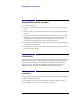
Contents Declaration of Conformity.................................................................... v Sales and Service Offices................................................................... viii Agilent Technologies 8922M/S Documentation Description............... x Typeface Conventions.......................................................................... xi 1 Installing Your Agilent 8922M/S Using this Chapter .............................................................................
Contents 4 Screens Field Types ........................................................................................ 4-2 Audio ................................................................................................ 4-4 Bit Error ............................................................................................ 4-8 Bit Error 2 ....................................................................................... 4-11 Cell Configuration - GSM 900 .......................................
Contents Pwr Ramp, Fall Edge ...................................................................... 4-99 Pwr Ramp: Summary .................................................................... 4-101 Pwr Ramp: Pulse (Option 006 Only) ............................................ 4-104 Pwr Ramp: Pulse Rise (Option 006 Only) .................................... 4-107 Pwr Ramp: Pulse Fall (Option 006 Only) ..................................... 4-109 RF Generator / RF Analyzer (AF Gen) ...........................
Contents 6 Connectors Front-Panel Connectors of the Agilent Technologies 8922M/S ....... 6-2 Rear-Panel Connectors of the Agilent Technologies 8922M/S....... 6-10 Signal Descriptions for SYSTEM BUS ......................................... 6-18 Timing Diagrams............................................................................. 6-27 7 Messages Communication Failures .................................................................. 7-2 Firmware Error ...............................................
Contents A APPENDIX A Purpose ............................................................................................. A-2 Equipment Required ......................................................................... A-3 Connecting the Agilent 8922M to the HP/Agilent 37900D ............. A-4 Setting Up the Agilent Technologies 8922M ................................... A-5 Setting Up the HP/Agilent 37900D .................................................. A-6 How to Obtain a Protocol Log................
Contents Contents-6
Warranty Warranty This Agilent Technologies instrument product is warranted against defects in material and workmanship for a period of one year from date of shipment. During the warranty period, Agilent Technologies will at its option, either repair or replace products which prove to be defective. For warranty service or repair, this product must be returned to a service facility designated by Agilent Technologies.
Responsibilities of the Customer Responsibilities of the Customer The customer shall provide; 1 Access to the products during the specified periods of coverage to perform maintenance. 2 Adequate working space around the products for servicing by Agilent Technologies personnel. 3 Access to and use of all information and facilities determined necessary by Agilent Technologies to service and/or maintain the products.
Notices Notices The material contained in this document is subject to change without notice. AGILENT TECHNOLOGIES MAKES NO WARRANTY OF ANY KIND WITH REGARD TO THIS MATERIAL, INCLUDING, BUT NOT LIMITED TO, THE IMPLIED WARRANTIES OF MERCHANTABILITY AND FITNESS FOR A PARTICULAR PURPOSE. Agilent Technologies inc. shall not be liable for errors contained herein or for incidental or consequential damages in connection with the furnishing, performance or use of this material.
Electromagnetic Compatibility (EMC) Information Electromagnetic Compatibility (EMC) Information This product has been designed to meet the protection requirements of the European Communities Electromagnetic Compatibility (EMC) directive: EN55011:1991 (Group 1, Class A) EN50082-1:1992 - IEC 1000-4-2 (1995) ESD - IEC 1000-4-3 (1995) Radiated Susceptibility - IEC 1000-4-4 (1995) EFT In order to preserve the EMC performance of this product, any cable which becomes worn or damaged, must be replaced with the sam
Declaration of Conformity Declaration of Conformity according to ISO/IEC Guide 22 and EN45014 Manufacturer’s Name: Agilent Technologies.
Safety Information Safety Information The following general safety precautions must be observed during all phases of operation of this instrument. Failure to comply with these precautions or with specific warnings elsewhere in this manual violates safety standards of design, manufacture, and intended use of the instrument. Agilent Technologies Inc. assumes no liability for the customer’s failure to comply with these requirements.
Safety Information DO NOT OPERATE IN AN EXPLOSIVE ATMOSPHERE Do not operate the instrument in the presence of flammable gases or fumes. DO NOT REMOVE THE INSTRUMENT COVER Operating personnel must not remove instrument covers. Component replacement and internal adjustments must be made only by qualified service personnel. Instruments that appear damaged or defective should be made inoperative and secured against unintended operation until they can be repaired by qualified service personnel.
Safety Symbols Safety Symbols The following symbols on the instrument and in the manual indicate precautions which must be taken to maintain safe operation of the instrument Safety Symbols The Instruction Documentation Symbol. The product is marked with this symbol when it is necessary for the user to refer to the instructions in the supplied documentation.
Sales and Service Offices Sales and Service Offices Any adjustment, maintenance, or repair of this product must be performed by qualified personnel. Contact your customer engineer through your local Agilent Technologies Service Center. You can find a list of local service service representatives on the web at: http://www.agilent-tech.com/services/English/index.html You can also contact one of the following centers and ask for a test and measurement sales representative.
Sales and Service Offices Canada Agilent Technologies Canada Inc. 5150 Spectrum Way, Mississauga, Ontario L4W 5G1 (tel) 1 877 894 4414 Europe: Agilent Technologies Test & Measurement European Marketing Organisation P.O. Box 999 1180 AZ Amstelveen The Netherlands (tel) (31 20) 547 9999 Latin America: Agilent Technologies Latin American Region Headquarters 5200 Blue Lagoon Drive, Suite #950 Miami, Florida 33126 U.S.A.
Agilent Technologies 8922M/S Documentation Description Agilent Technologies 8922M/S Documentation Description Documentation Shipped with Your GSM Test Set Agilent 8922M/S GSM Test Set Quick Start Guide. This guide gives a brief description on how to make each of the measurements required to test a GSM mobile phone. More detailed descriptions are given in the Agilent 8922M/S GSM Test Set User’s Guide. Agilent 8922M/S GSM Test Set User’s Guide.
Typeface Conventions Typeface Conventions Italics Italic type is used for emphasis. Display Display text is used to show examples, fields, and prompts that are displayed on the Agilent 8922M/S screen. PRESET Keycaps on the Agilent 8922M/S keyboard are enclosed in boxes. Soft keys Display text is used to show examples, fields, and prompts that are displayed on the Agilent 8922M/S screen. Soft keys All software listings in this manual can be identified with this font.
1 Installing Your Agilent 8922M/S 1-1
Installing Your Agilent 8922M/S Using this Chapter Using this Chapter Use the following procedure to get the Agilent Technologies 8922M/S powered-up correctly. After completing this procedure, refer to the Quick Start Guide for an introduction to operating the Agilent Technologies 8922M/S and Chapter 2, “Making Measurements” for more extensive information on using the Agilent Technologies 8922M/S.
Installing Your Agilent 8922M/S Fuses and Power Cords Fuses and Power Cords CAUTION Before plugging this instrument into the Mains (line) voltage, be sure the correct voltage on the line voltage selection card has been selected. Line Voltage and Fuse Selection Verify that the line voltage selection card is matched to the power source (see Figure 1-1 on page 1-3). Order fuse Agilent part 2110-0083 (2.5 A 250 V, normal blow) for replacement.
Installing Your Agilent 8922M/S Fuses and Power Cords Power Cords Agilent Part Agilent 1-4
Installing Your Agilent 8922M/S Installation Overview Installation Overview 1 2 Connect a 1, 2, 5, 10, or 13 MHz signal to the REF IN. If you are using option 001, connect as shown, see Figure 1-2 on page 1-5, with the supplied cable (OPT 001 REF OUT to REF IN). Connect the supplied power cord to the Agilent 8922M/S and power up the instrument.
Installing Your Agilent 8922M/S Installation Overview 3 Figure 1-3 Access the CONFIG screen to customize the set-up of your Agilent 8922M/S. This is done by: • Moving to the CONFIG field in the bottom right-hand corner of the Cell Control screen, (the first screen that appears after power-up or after selecting PRESET ). Rotate the cursor control knob (refer to “a”, see Figure 1-3 on page 1-6) until you are on the CONFIG field.
Installing Your Agilent 8922M/S Installation Overview 4 To guarantee the correct operation of the Agilent 8922M/S with all mobile phones, you should use a high-stability timebase. This step details how to configure the Agilent 8922M/S for use with either the option 001, high-stability timebase, or an external reference signal. A If you have option 001 installed and wish to use this as your reference, ensure that the OPT 001 REF OUT field in the Configure screen is set to On.
Installing Your Agilent 8922M/S General Information General Information Operation and Storage Environment Refer to General Specifications in the Agilent 8922M/S Specifications section of Chapter 3, Performance Verification for information about the operation or storage environment. Instrument Options Refer to Agilent 8922M/S Specifications in Chapter 3, Performance Verification for information about instrument options.
2 Making Measurements 2-1
Making Measurements Using This Chapter Using This Chapter Use this chapter to obtain an overview of how to operate the Agilent 8922M/S GSM Test Sets. This chapter is divided into the following sections: • • Making Measurements • Agilent 8922M/S Operating Modes - explains how to configure the Agilent 8922M/S so that measurements can be made. • Measurements - details how to perform the many different measurements available on the Agilent 8922M/S.
Making Measurements Agilent Technologies 8922M/S Operating Modes Agilent Technologies 8922M/S Operating Modes This section details the procedures necessary to control the Agilent 8922M/S and GSM mobile phone in each of the main operating modes. It is recommended that you read this section before attempting the “Measurements” section.
Making Measurements Agilent Technologies 8922M/S Operating Modes To configure the Agilent 8922M/S to the desired operating mode, carry out the following instructions, referring to Figure 2-1 on page 4 for the position of the fields. • NOTE Ensure (1) is set to mobile phone type you require (GSM900, E-GSM, DCS1800, or PCS1900). For use with DCS1800 or PCS1900, refer to the HP/Agilent 83220A/E Users Guide which explains how to configure the Agilent 8922M/S to test other mobile phone formats.
Making Measurements ACTIVE CELL ACTIVE CELL This is the default mode after cycling the power or selecting PRESET . A functional mobile phone will lock on (camp on) to a signal which is produced by the Agilent 8922M/S. The characteristic of this signal appears in the BASE STATION fields, (1), see Figure 2-2 on page 2-6. These fields show the Channel number and the Amplitude of the signal.
Making Measurements ACTIVE CELL 3 2 3 4 6 5 Figure 2-2 Active Cell Mode Making a Call From To call (or page) the mobile phone from the Agilent 8922M/S, it is necessary for the the Agilent 8922M/S Agilent 8922M/S to know the number of the SIM in the mobile phone. [This number to the Mobile Phone is the International Mobile Subscriber Identity (IMSI). This and other information is stored on the SIM card.] NOTE The Network number cannot be used to make a call.
Making Measurements ACTIVE CELL Press the following keys to do this: • • • SHIFT , CELL CONFIG (MS INFO) Move the cursor to the Paging IMSI field and enter the IMSI using the numeric data entry keypad. CELL CNTL , ORG CALL Performing a “location update” from the MS INFO screen allows the Agilent 8922M/S to update the IMSI. This can be done by either: • changing the Current location parameters and waiting for the mobile phone to re-camp. • setting IMSI Attach/Detach to On before powering on the phone.
Making Measurements ACTIVE CELL There may be many reasons for the measured level not being close to the expected level. The two most likely are that, either, the mobile phone is not operating correctly, or, there is some power loss between the Agilent 8922M/S RF IN/OUT connector and the mobile phone. If you suspect it is the second case, you can compensate the Agilent 8922M/S generator settings and measurement results for external losses or gains.
Making Measurements TEST MODE TEST MODE To enter this mode, select TEST MODE as described in the section titled “Agilent 8922M/S Operating Modes”. In TEST MODE, the Agilent 8922M/S no longer controls the mobile phone. The TEST MODE is used when it is not desired, or not possible, to set up a call between the Agilent 8922M/S and the mobile phone. The MOBILE PHONE area available in Active Cell controls three functions simultaneously: • • • The traffic channel transmitted by the Agilent 8922M/S.
Making Measurements TEST MODE NOTE While the Test Mode is selected, the three MEASURE ON parameters are also available on the bottom right-hand side of all measurement screens. This provides control of the Expected Input parameters during measurements. 4 1 2 3 Figure 2-3 Test Mode Mobile Phone To measure an incoming signal from the mobile phone’s transmitter, perform the Transmitter Testing following steps: Using Test Mode • Select TEST MODE.
Making Measurements TEST MODE Code is not known, it can be determined and corrected from measurements described later. Refer to the “Advanced Features” section mentioned later in this chapter. NOTE In the Active Cell mode, the Colour Code is automatically set. Once these have been selected, the Agilent 8922M/S is ready to measure incoming signals of the type specified. The mobile phone should be set up to generate a corresponding test signal to the one expected.
Making Measurements CW GENERATOR CW GENERATOR To enter this mode, select CW GENERATOR as described in the section titled “Agilent 8922M/S Operating Modes”. The CW Generator mode has the same measurement capabilities as the Test Mode but replaces the GSM BCH and forced TCH signals with a single unmodulated RF carrier. The frequency and amplitude of the Continuous Wave (CW) signal is controlled by the Channel, Amplitude, and the Frequency fields (1).
Making Measurements Measurements Measurements The measurements available on the Agilent 8922M/S can all be accessed from the cell control screen by selecting a measurement field under MEASUREMENTS, (see Figure 2-5 on page 2-13) and pushing the knob. GSM Specific Measurements The measurements available are: Ancillary Measurements You can also use the toolkit capabilities of the Agilent 8922M/S.
Making Measurements Measurements After making one type of measurement, another can be made by simply pressing CELL CNTL and, using the knob, selecting the next measurement of your choice. Peak Carrier Power The peak transmitter carrier power averages the transmitter carrier power for a Measurement single burst. This average is calculated over the time that the data information bits are transmitted.
Making Measurements Measurements Phase and Frequency Error Measurement Phase error and frequency error are measures of the modulation and noise performance of the radio’s transmitter path. Method Select the PHASE FRQ field on the cell control screen to access the phase and frequency measurements. NOTE The test is run automatically when the screen is selected. The measurement fields in this screen are RMS Phase Error, Peak Phase Error and Frequency Error (1), see Figure 2-7 on page 2-15.
Making Measurements Measurements These are: • • Power Ramp Mask Measurements PHASE ERR - this displays the phase error graphically. The phase error trace is displayed using an autoscaling phase error axis versus data bits (numbered 0 through 147). DATA BITS - this screen allows you display a screen which details the values of the 148 bits in the timeslot (including midamble). If a known test signal is being used, the reception of these bits can be verified.
Making Measurements Measurements The power ramp measurements are divided into three screens where you can view different parts of the signal and one screen which displays a series of amplitude values at various times during the burst. These screens can be revealed by highlighting and selecting from the View field (2): • • • • Rise Edge - displays the top 30 dB of the rising section of the waveform.
Making Measurements Measurements Pulse Measurements If you have option 006 (spectrum analyzer) installed, you can make measurements (Available if Option on the lower portion of the pulse. These measurements can be accessed from the 006, Spectrum Power Ramp screens.
Making Measurements Measurements Bit Error Rate Measurement The Bit Error Rate measurement allows you to test the sensitivity of the mobile phone’s receiver. By reducing the signal transmitted by the Agilent 8922M/S, you can test the ability of the receiver to accurately decode its incoming signal. Data bits that are decoded are sent back to the Agilent 8922M/S. The Agilent 8922M/S compares them to original signal that was sent out and the differences are derived from this.
Making Measurements Measurements By varying the Base station Amplitude field (4), you can test the mobile phone’s receiver sensitivity. Actual results can be compared with the values reported by the radio. NOTE If the Base Station amplitude is lowered too much, the radio will lose the call. This will need to be re-established by increasing the base station amplitude, returning to the cell control screen, and originating the call before you can continue measurements.
Making Measurements Measurements This sets the reference level to which the offset frequency values are compared. • • Select Ramping or Modulation (3). Set your Freq Offset value (4). 5 2,3 Figure 2-11 Output RF Spectrum Measurements • Output RF Spectrum Measurements Using a 3-Pole Synchronously Tuned Measurement Filter 1,4 The trace of the output RF spectrum can be viewed if you highlight View and select Trace (5). GSM Recommendation 11.10 and 11.
Making Measurements Measurements In the Agilent 8922, Output RF Spectrum measurements are made using a 3-pole synchronously tuned measurement filter. The measurement results will differ from measurements using a 5-pole filter. The difference between measurements of the “ideal” signals using a 3-pole filter and a 5-pole filter are shown in Table 1 and Table 2.
Making Measurements Measurements Table 3 Table 4 Adjusted Limits Based on 3-Pole Filter Output RF Spectrum Due to Modulation Power Control Level Offset from Carrier (kHZ) 0 100 200 250 400 600 to 1800 0 (43 dBm) 0 dB 0.5 dB -27.5 dB -32 dB -51 dB -70 dB 0 (39 dBm) 0 0.5 -27.5 -32 -51 -66 0 (37 dBm) 0 0.5 -27.5 -32 -51 -64 ≥5 (≤ 33 dBm) 0 0.5 -27.
Making Measurements Measurements Spectrum Analyzer (Available if Option 006, Spectrum Analyzer, is Fitted) The spectrum analyzer allows you to view the mobile phone’s signal over a wide dynamic range. It also allows you to view any adjacent interference which may exist. NOTE The spectrum analyzer can detect very low power signals where Active Cell and even Test Mode cannot operate. Broken cable or connectors can be found using this function. Method Select SPEC ANL in the cell control screen.
Making Measurements Measurements NOTE The RF Generator and spectrum analyzer can be tuned to different frequencies allowing the inspection of the IF signals inside the mobile phone. 1 2 Figure 2-12 3 Spectrum Analyzer Measurement Use the MeasReset (2) to reset the trace and measurements in the Agilent 8922M/ S. This is useful if you are using the Max Hold field (3). The resolution bandwidth of the spectrum analyzer is automatically coupled to the frequency span.
Making Measurements Measurements Scope The oscilloscope function of the Agilent 8922M/S allows you to view the demodulated signal from the mobile phone. This can be used for fault-finding in the audio path. Select SCOPE in the cell control screen to gain access to the oscilloscope function of the Agilent 8922M/S. Selecting (1), see Figure 2-13 on page 2-26, gives access to other functions of the oscilloscope.
Making Measurements Measurements Audio The audio function measures the audio frequency and voltage of the demodulated signal from the mobile phone or from a number of other sources selectable using AF Anl In (5), see Figure 2-14 on page 2-27. Select AUDIO in the cell control screen to gain access to the audio function of the Agilent 8922M/S. The measurements of the audio voltage and frequency commence within a short time of the screen being accessed.
Making Measurements Measurements CW Measurement The CW Measurement screen displays the carrier frequency and power of a continuous (non-pulsed) signal. The CW Power measurement offers a greater dynamic range than is available when making pulsed measurements. CW Power is a broadband measurement. The CW Frequency measurement is obtained using a tuned, selective input. The RF analyzer should be set to within 500 kHz of the expected signal frequency.
Making Measurements Measurements NOTE Although CW Measurements is a broadband measurement, it uses calibration data that relies on the expected input frequency being set correctly. The Power Detector is connected so that it will only make measurements on signals present at the RF In/ Out port.
Making Measurements If You Have Problems with a Measurement If You Have Problems with a Measurement This section tells you what to do if either of the following screen display events occurs: • Message Line Messages (on the top of the screen). • • • Is a Message Line displayed at the top of the screen. Possible Solutions to Message Line Errors. Sync Status Messages • Is an Error Message Displayed in the Sync Status Field. Refer to Chapter 7, “Messages”, for more information.
Making Measurements If You Have Problems with a Measurement Figure 2-16 2-31
Making Measurements If You Have Problems with a Measurement Possible Solutions to The signal processing hardware that is used to generate measurement results has to Message Line Errors be told when to take data samples. If the trigger to do this is misaligned with the signal, there may be errors in the results that are displayed. Trigger Timing A Check if the trigger is being received. On the MEAS SYNC screen (press MEAS SYNC to gain access), check if the correct burst type has been defined.
Making Measurements If You Have Problems with a Measurement Trigger Range For Pulsed RF 2-33
Making Measurements If You Have Problems with a Measurement Is an Error Message The sync status field displays an error message for the following errors: Displayed in the • Bad Sync - demodulation error, perform a Phase/Frequency error measurement Sync Status field? to identify which of the Sync Status error listed below may be the possible problem.
Making Measurements If You Have Problems with a Measurement Possible Solutions to Solution 1 - Trigger Timing Sync Status Errors Check if the trigger is being received. On the MEAS SYNC screen (press MEAS SYNC to gain access), check if the correct burst type has been defined. On the Data Bits screen: A The First Bit field on the Phase Freq:Data Bits screen displays the time difference between when a trigger is being received and when the first bit of a burst occurred (A).
Making Measurements If You Have Problems with a Measurement Solution 2 - Midamble Sync On the MEAS SYNC screen (press MEAS SYNC to gain access), • Check the definition of the signal’s burst type (A). • Check the Burst Sel field (B). A B Check the bit pattern of your measurement Perform a Data Bits measurement (D). An “M” will display under the bits that are identified as the midamble bits.
Making Measurements If You Have Problems with a Measurement Solution 3 - Level Check the following fields on the RF Generator/RF Analyzer screen (press SHIFT , CELL CNTL , (RFG/RFA) to gain access). 3 Pulse field (a), (if signal is pulsed) Ext or Hop Trig should be selected. 4 Amplitude field (b), for the expected amplitude 5 Frequency field (c), for the correct frequency. 6 RF Input field (d), for the correct connector choice. 7 AGC Mode field (e).
Making Measurements If You Have Problems with a Measurement Solution 4 - Amplitude Envelope • Check if the Pulse Amplitude is ± 1 dB of the expected value during the useful part of the burst. If FM Errors: Perform a Phase Freq:Data Bits measurement. Dashes (a) will display under the bits where the power is too low. If No FM Errors: Perform pulse demodulation measurements. Connect PULSE (DEMODULATION OUT) connector to SCOPE IN (MEASURE) connector on the front panel.
Making Measurements Advanced Features Advanced Features Other Screens The screens mentioned in this section are not necessary for simple measurement of mobile phones as the work is done by the functions mentioned previously. However, the advanced user may find it worthwhile to know what these screens are and what they are capable of doing. • RF Generator/RF Analyzer - this screen controls the Agilent 8922M/S RF generator and RF analyzer.
Making Measurements Advanced Features • Using RF Rise Triggering SMS Cell Broadcast - the SMS CB screen allows you to test whether the mobile phone is capable of correctly receiving and displaying a message sent from a base station using the Short Message Service (SMS) Cell Broadcast protocol. This screen can be accessed by highlighting the More field in any main screen and selecting SMS CB.
Making Measurements Advanced Features Power Ramp Setting The mobile transmitter output ramp should settle so that it complies with the power Time mask (GSM Rec 11.10) by the time output level calibration is done in the manufacturing process. The power mask is displayed in the Power Ramp screens. Peak Carrier Power measurement method is not made to GSM Rec. 11.10. If you need to make a measurement to this specification, go to the Power Ramp Summary screen.
Making Measurements Advanced Features The beginning of the 0 sample bin will be between 0 and 75µS (bit 0 - 20) after the trigger as the sampler runs asynchronously to the trigger. The last sample bin will complete sampling between 450µS and 525µS (bit 121 - 142) into the burst. The measurement processor discards the 0 sample bin. This effectively removes the ramp-up overshoot. Each measurement is also RF Power Qualified to ensure only valid bursts are measured.
Making Measurements Advanced Features NOTE The GPIB requires the use of base 10 values, 432h = 1074d, for example: SERV:LATCH:VAL 1074. 2 The value entered is relative to the beginning of the zero bit of the zero slot on the downlink baseband. A 4.7 bit modulator delay occurs between the baseband and the RF domain which must also be taken into account. Since the value may only be integer, round to the nearest whole value. The following timing error is introduced due to 156/157 bit timing.
Making Measurements Advanced Features Unexpected Operations NOTE These are descriptions of operations which may be unclear to the user as to how they occurred. These are NOT defects. 1 The Agilent 8922M/S occasionally sends ABORTS to the attached protocol monitor. These ABORTS are normal and logging data is not lost. 2 In the FA and SD/4+FA control channel configurations, the Agilent 8922M/S sends speech frames rather than fill frames on the FACCH when there is nothing else to send.
Making Measurements Advanced Features 9 The RF Generator may become uncalibrated in a hopping situation when the last CW frequency setting was outside the GSM or DCS band. If you are using the RF Generator outside the normal GSM or DCS bands, make sure you set a valid GSM or DCS frequency in the CW frequency before entering a hopping mode. This includes the ACTIVE CELL (ACTIVATED state on the CELL CONFIG 2 screen) on the Agilent 8922M/S.
Making Measurements Advanced Features 12 Some measurement results may be displayed as ---- due, for example, to mobile failure. The measurement has been armed but has not completed. In these circumstances a GPIB query of the measurement will not return a result. This event should be catered for by adding a time-out to the query and a “CLEAR” operation as described in paragraph 11, above. 13 When changing between screens, the DSP results may briefly show a very large number. This is expected behavior.
Making Measurements Advanced Features 2-47
3 Verifying Performance 3-1
Verifying Performance About This Chapter About This Chapter The tests in this chapter verify the electrical performance of the Agilent 8922M/S GSM Test Set using the Agilent 8922 Performance Test Software provided with the product. If the instrument passes this verification, its operation and specifications are assured within the measurement uncertainties provided in the performance test print out.
Verifying Performance Setting up the Tests Setting up the Tests This chapter contains the following information: Getting the Right Test Equipment Required Test Equipment lists the test equipment needed for the performance tests. This is the only equipment supported by the Agilent 8922 Performance Test Software and is required to verify instrument operation. Equipment substitutions or manual performance tests are not recommended or supported by Agilent Technologies.
Verifying Performance Getting the Right Equipment Getting the Right Equipment The following equipment is required to do all of the performance tests. The test descriptions have an equipment list that specifies the equipment used for each particular test. Equipment 3-4 HP/Agilent Model Number Measuring Receiver 8902A Sensor Module 11722A Audio Analyzer 8903B Voltmeter 3456A Signal Generator 8657A/B Opt. 022 Multifunction Synthesizer 8904A Opt.
Verifying Performance Installing and Operating the Software Installing and Operating the Software Performance Test Software is supplied on a 3.5-inch, double-sided floppy disk and is written to run with BASIC 5.0 and later. Modifications to the program should be limited to changing the default addresses and storing copies for back-up purposes. Understanding the Tests Test Descriptions contains a description of each test that is performed by the Performance Test software.
Verifying Performance Installing and Operating the Software Forward Conversion To return the instrument from an Agilent 8922G back to an Agilent 8922M or an Agilent 8922E to an Agilent 8922S, select the following keys: • • • • More (this is accessible from the Cell Control screen in the bottom right-hand corner). Scroll down the list and select CONFIG. Compatible, select 8922M or 8922S HP-IB Adrs (14) PRESET The instrument is returned to an Agilent 8922M or Agilent 8922S.
Verifying Performance Understanding the Tests Understanding the Tests This section describes the theory of each performance test, lists the equipment needed for the test, and provides some problem solving information. Test 01: Signal Generator Level Equipment Required Measuring Receiver HP/Agilent 8902A Sensor Module HP/Agilent 11722A Theory of the Test The UUT is set to generate CW signals at various levels and frequencies.
Verifying Performance Understanding the Tests Test 02: Signal Generator Spectral Purity Equipment Required HP/Agilent 8566B Spectrum Analyzer Theory of the Test The UUT is set to generate a CW signal at various levels and frequencies. The HP/ Agilent 8566B is used to measure the signal level and then the level of the harmonics or spurious signals.
Verifying Performance Understanding the Tests Test 04: Signal Generator 0.3 GMSK Modulation Equipment Required (excluding Agilent 8922S) HP/Agilent 8904A Option 001/002 Multifunction Synthesizer Theory of the Test The HP/Agilent 8904A is used to generate a 270.833 kHz clock and random data. This drives the UUT RF generator to generate the 0.3 GMSK modulated signals with random data. This signal is then analyzed by the UUT to assure that the frequency and phase errors are correct.
Verifying Performance Understanding the Tests Test 06: Audio Equipment Required Frequency Analyzer HP/Agilent 8904A Option 001/002Multifunction Synthesizer HP/Agilent 3456AVoltmeter Theory of the Test The HP/Agilent 8904A is used to generate accurate test signals which are analyzed by the UUT. The voltmeter is used to reduce measurement uncertainty by accurately characterizing the test signal level to predict the correct response of the UUT.
Verifying Performance Understanding the Tests faulty also. If the front panel reading from the UUT is significantly different from the printed “measured” response, the normalization may be the cause. If the oscilloscope triggers incorrectly, the peak search may not find the actual peak response on the display.
Verifying Performance Understanding the Tests clock signal. The option does not have GPIB control so the program cannot verify that the option is operational. Test A: RF Analyzer Equipment Required Pulse Demodulation HP/Agilent 8657A/B Signal Generator HP/Agilent 8116A Pulse Generator Theory of the Test The Pulse generator drives the signal generator to generate Pulsed RF signals at various frequencies.
Verifying Performance Understanding Test Failures Understanding Test Failures This section is intended to be used in conjunction with the Agilent 8922 Series Assembly Level Repair Guide for assembly level repair and troubleshooting. If a performance test fails and hardware is suspected, the following table is a guideline to help identify the hardware assemblies most likely to cause each failure.
Verifying Performance Agilent Technologies 8922M/S Specifications Agilent Technologies 8922M/S Specifications NOTE: If you have the Agilent 8922M/S Option 010 Multi-Band Test System, refer to the appropriate Agilent 8922 Multi-Band User’s Guide for more information on specifications relevant to dual band testing. GSM900 and E-GSM900 Functionality Bit/Frame Error Rate Measurements: Class 1a, 1b, and Class II bits in both raw and residual form.
Verifying Performance Agilent Technologies 8922M/S Specifications Supplemental Characteristics: Frequency Overrange To 1015 MHz with uncalibrated output and modulation Switching Speed 577 µs over the GSM frequency bands in hop mode (refer to 0.3 GMSK modulation specs Output RF In/Out Connector −14 to −127 dBm Level Range Level Resolution Level Accuracy 0.1 dB 2 GSM Bands1 50 MHz to 1 GHz 10 MHz to 50 MHz Reverse Power SWR Aux RF Out Connector Level Range Level Resolution ±1.
Verifying Performance Agilent Technologies 8922M/S Specifications Spectral Purity Spurious Signals (for ≤+1 dBm output level at Aux RF Out or ≤−19 dBm output level at RF In/Out. Harmonics: <−25 dBc Non-harmonics: <−50 dBc, >5 kHz offset from carrier 0.3 GMSK Modulation After one timeslot, 577µs, from an isolated RF Generator Trigger in the GSM Frequency bands. Phase Error ≤1° rms Peak Phase Error ≤4° peak Frequency Error ± [0.02 ppm (18 Hz) + reference accuracy], for normal bursts Typically ±[0.
Verifying Performance Agilent Technologies 8922M/S Specifications 30 dB Pulse Modulation (Agilent 8922M only) All timeslots 30 dB higher than desired/active timeslot, to test adjacent timeslot rejection. Supplemental Characteristics: Input Levels TTL Rise/Fall Time (10 to 90%) ≤5 µs AM for Level Control (Agilent 8922M Only) For output levels ≤+1 dBm at Aux RF Out or ≤−19 dBm at RF In/Out Supplemental Characteristics: Input Range −1.0V to +0.
Verifying Performance Agilent Technologies 8922M/S Specifications RF Analyzer Specifications Frequency Range 10 MHz to 1 GHz Resolution 1 Hz Hop Mode Resolution 100 kHz Offset Frequency ≤50 kHz Offset Resolution 1 Hz RF In/Out SWR <1.
Verifying Performance Agilent Technologies 8922M/S Specifications Peak/Transmitter Carrier Power Measurement RF In/Out only. After one timeslot, 577 µs, from an isolated Receiver Hop Trigger in the GSM bands. Range -5 to +41 dBm Input Frequency Setting Error ±10 kHz Input Level Setting Error ±3 dB Accuracy ±0.6 dB ± noise effects (+4 to +41 dBm) (0.2 mW) Supplemental Characteristics: Accuracy ±0.6 dB ± noise effects (-5 to +4 dBm) (0.2 mW) Minimum Resolution 0.
Verifying Performance Agilent Technologies 8922M/S Specifications Accuracy (ON/OFF 40 dB, RF In/Out only) OFF Power (dBm) ON/OFF Ratio Accuracy −30 to −1 ±2.4 dB ±1.1 typically −37 to −30 ±2.9 dB ±1.3 typically −42 to −37 ±3.7 dB ±1.7 typically −47 to −42 ±4.2 dB ±2.
Verifying Performance Agilent Technologies 8922M/S Specifications Phase and Frequency Measurements After one timeslot, 577µs, from an isolated Receiver Hop Trigger in the GSM Frequency bands. Range RF In/Out −6 to +41 dBm Aux RF In −36 to +20 dBm Input Frequency Setting Error ±10 kHz Input Level Setting Error ±3 dB RMS phase error accuracy ≤1° rms Peak phase error accuracy ≤4° peak Frequency error accuracy ±[0.02 ppm (18 Hz) + reference accuracy], for normal bursts. Typically ±[0.
Verifying Performance Agilent Technologies 8922M/S Specifications FM Demodulation Output (Agilent 8922M only) Range RF In/Out −6 to +41 dBm Aux RF In −36 to +20 dBm Sensitivity 20µV/Hz ±5% (into an open circuit) Input Frequency Setting Error ±50 kHz, with ≤100 kHz pk deviation Input Level Setting Error ±3 dB Supplemental Characteristics 3 dB Bandwidth DC to 270 kHz Output Impedance 600 Ω DC Offset ≤5 mV Pulse Demodulation Output (Agilent 8922M only) Range RF In/Out −6 to +41 dBm Aux RF In
Verifying Performance Agilent Technologies 8922M/S Specifications Output RF Spectrum Measurement (Requires Option 006) After one timeslot, 577µs, from an isolated Receiver Hop Trigger in the GSM Frequency bands. Range RF In/Out −6 to +41 dBm Aux RF In −36 to +20 dBm Input Levels for Optimum Dynamic Range RF In/Out +7, +17, +27, +37 dBm Aux RF In −23, −13, −3, +7 dBm Input Frequency Setting Error ±10 kHz, Input Level Setting Error ±3 dB Supplemental Characteristics: Log Linearity ±0.
Verifying Performance Agilent Technologies 8922M/S Specifications Spectrum Analyzer Specifications (Option 006) Frequency Range 10 MHz to 1 GHz Frequency Span/Resolution Bandwidth (coupled) Span Bandwidth <50 kHz 300 Hz <200 kHz 1 kHz <1.5 MHz 3 kHz ≤4 MHz 30 kHz Display Log, 10 dB/div Display Range 80 dB Log Linearity ±1.
Verifying Performance Agilent Technologies 8922M/S Specifications Audio Source Specifications Frequency Range DC to 25 kHz Accuracy 0.025% of setting Supplemental Characteristics Minimum Resolution 0.1 Hz Output Level Range 0.1 mV to 4 Vrms Maximum Output Current 20 mA peak Output Impedance <1 Ω Accuracy ±(2% of setting + resolution) Residual Distortion (THD + noise, amplitude >200 mV rms) 0.1%, 20 Hz to 25 kHz in 80 kHz BW. Supplemental Characteristics Minimum Resolution Level ≤0.
Verifying Performance Agilent Technologies 8922M/S Specifications AC Voltage Measurement Voltage Range 0 V to 30 Vrms Accuracy (20 Hz to 15 kHz), ±3% of reading Input >1 mVrms Residual Noise + THD (15 kHz BW) 175 µV Supplemental Characteristics 3 dB Bandwidth 2 Hz to 100 kHz Input Impedance 1 MΩ 145 pF at AUDIO IN Minimum Resolution 4 digits for inputs ≥100mV 3 digits for inputs <100 mV DC Voltage Measurement Voltage Range 100 mV to 42 V Accuracy ±(1.
Verifying Performance Agilent Technologies 8922M/S Specifications Audio Filters There are seven filters used in the Agilent 8922M/S.
Verifying Performance Agilent Technologies 8922M/S Specifications Remote Programming GPIB IEEE Standard 488.2 Functions Implemented SH1, AH1, T6, L4, SR1, RL1, LE0, TE0, PP0, DC1, DT1, C4, C11, E2 RS-232 3 wire RJ-11 connector used for serial data in and out. Baud Rates 300, 1200, 2400, 4800, 9600, and 19200 selectable. General Specifications Size 177H × 426W × 574D mm (7 × 16.75 × 23 in).
Verifying Performance Agilent Technologies 8922M/S Specifications Operating Environment This instrument is designed for indoor use only. CAUTION This instrument is designed for use in Installation Category II and Pollution Degree 2 per IEC 1010 and 644 respectively. CAUTION Before switching on this instrument, make sure that the line voltage selector switch is set to the voltage of the power supply and the correct fuse is installed. Assure the power supply voltage is in the specified range.
Verifying Performance Agilent Technologies 8922M/S Specifications Reference Specifications The accuracy needs for testing GSM radios require the unit to be operated with the High Stability Reference (Option 001) or an external high stability reference.
Verifying Performance Agilent Technologies 8922M/S Specifications 3-31
4 Screens NOTE If you have the Agilent 8922M/S Option 010 Multi-Band Test System, refer to the appropriate Agilent 8922 Multi-Band User’s Guide for more information on additional screens and screen differences.
Screens Field Types Field Types 1. Alphanumeric This field is where you enter names or titles. To enter, position the cursor next to a character or edit function, then push the knob to select it. (A list of character and function choices appears in the bottom-right corner of the screen.) 2. Data Entry This field is where you enter numeric values. To enter a numeric value, position the cursor next to the field and change the value in one of two ways: • • 3.
Screens Field Types 4. Underlined Entry This type of field allows selection between the two labels in the field separated by a slash (/). To toggle between the choices, position the cursor next to the field and push the knob. The underlined choice is activated. 5. To Screen List This field allows selection of alternate screens. To change to another screen, position the cursor next to the required screen and push the knob.
Screens Audio Audio 1. AC Level This field displays the measured ac level of the AF analyzer input (AF Anl In) when Audio Out, Pls Demod, Audio In, Speech In, Speech Out, or Scope In is selected as the input. See Also 2. AF Freq This field selects the type of measurement to be made on the input signal. The input signal to be measured is selected in the AF Anl In field. Choices See Also 3. AF Anl In Keys: ON/OFF, HI LIMIT, LO LIMIT, REF SET, AVG, METER, Units AF Freq measures the audio frequency.
Screens Audio Choices Scope In selects the SCOPE IN (MEASURE) front-panel connector. Speech Out selects the signal going to the MON/SPEECH (DEMODULATION OUT) front-panel connector. AM Mod In selects the IN AM/SPEECH (MODULATION) frontpanel connector. Speech In selects the IN AM/SPEECH (MODULATION) frontpanel connector. FM Demod selects the FM demodulation discriminator. Pls Demod selects the pulse demodulation detector. Audio In selects the (AUDIO IN HI) front-panel connector.
Screens Audio 10. Meas Reset (Meas Cntl) Selecting Meas Reset will erase any accumulated measurements used for calculating a final result, and re-start the measurement process for the following functions: • • • HI LIMIT LO LIMIT AVG This field resets the AF Analyzer measurements. See Also Keys: HIGH LIMIT, LO LIMIT, AVG 11. Speaker ALC This field selects the Speaker ALC mode. ON maintains the speaker output at a constant amplitude for audio signals of different levels.
Screens Audio 13. Speech This field selects the speech mode. Choices NOTE None Uncond (unconditioned) activates the MODULATION IN AM/SPEECH connector on the front panel, but the speech signal is not conditioned by filters, and no gain control is provided. Cond (conditioned) activates the MODULATION IN AM/SPEECH connector on the front panel and conditions speech through filters. Gain control is available in the Speech Gain field. DCAM must be off when Cond is selected.
Screens Bit Error Bit Error 3 15 7 15 9 4 15 15 2 12 8 14 13 5 1. Amplitude (Base Station) 1 6 11 This field changes the RF generator amplitude. It is a duplicate of the RF generator’s Amplitude field on the RF Generator/RF Analyzer screen. See Also 2. BE Ratio 10 Screens: RF Generator/RF Analyzer (RF Generator). This field selects how bit errors will be displayed. Choices BE Count displays the total number of bit errors.
Screens Bit Error 5. Bits (Measure) This field selects the number of bits which will be tested. This number includes only bits that are tested by the selected measurement type. 6. CRC or FE These fields determine what data will be displayed. Choices CRC displays cyclic-redundancy-check (CRC) errors. FE displays frame erasures. 7. CRC/FE Ratio This field displays the result of the CRC or FE ratio after all the bits have been tested. 8.
Screens Bit Error 12. Res Type (Measure) Residual Type field selects the type of bit error test results to display. (Res means residual). Choices TypeIa ResTypeIa TypeIB ResTypeIB TypeII ResTypeII TypeI ResTypeI AllFS ResAllFS Off 13. Run/Stop (Control) Run starts a bit error test. Stop discontinues the bit error test in progress. 14. Single/Cont (Control) Single allows one test to be performed. Cont allows testing to automatically repeat. 15.
Screens Bit Error 2 Bit Error 2 Each time the Bit Error Test is run, four measurements are made (see Meas Num). Because of limited screen space, only two measurements are displayed at one time. The upper left side of the screen will display measurement 1 or 3, and the upper right side will display measurement 2 or 4. For further information, read the field description for Meas Num.
Screens Bit Error 2 NOTE This field is not featured in the Agilent 8922S. 2. Amplitude This field changes the RF generator amplitude. It is a duplicate of the RF generator’s Amplitude field on the RF Generator/RF Analyzer screen. See Also Screens: RF Generator/RF Analyzer (RF Generator). 3. Atten Hold This field turns the attenuator hold on or off. 4/5. BE Ratio/BE Count These fields select how bit errors will be displayed for both the Intermediate and Completed results.
Screens Bit Error 2 11/19. Ratio/Count These fields select how frame errors/CRC errors will be displayed for both the Intermediate and Completed results. Choices Error displays the frame errors/CRC as a percentage per measurement. Count calculates and displays the total number of bit errors counted to the total number of bits measured (depends on measurement type). Field (11) displays the final result of the measurement, field (19) displays a running total of the bit errors. 12.
Screens Bit Error 2 18. 0.0 (Reference) This field is used to adjust the reference offset when using the tunable reference. 19. Count or Ratio This field determines how the frame erasures or cyclic-redundancy-check (CRC) errors will be displayed. Choices Type Count displays the number of frame erasures or cyclicredundancy-check (CRC) errors. Ratio displays the ratio of frame erasures or cyclic-redundancycheck (CRC) errors to total frames.
Screens Bit Error 2 24. MS Loopback This field is used to enter or display amount of delay (expressed in number of speech frames), before bits are compared. The Agilent 8922 uses this value to synchronize to the correct received PRBS speech frame. The correct number of speech frames can be determined automatically by making a Bit Error Test using Auto Mode when the bit error ratio is approximately <20%.
Screens Cell Configuration - GSM 900 Cell Configuration - GSM 900 1,17 5 7 2 10 11 13 12 16 6 3 Activated 8 4 14 15 9 When Activated is displayed, the Agilent 8922M/S is operating as a base station simulator, and calls can be attempted. Most settings affecting cell configuration are not settable (cannot be changed) while Activated. Choices Activated means that most of the Cell Configuration screen’s settings are in use (activated) and cannot be changed.
Screens Cell Configuration - GSM 900 Field RF Gen, Hop Trig RF Anl, Hop Trig Hop Address, Address Source RF Gen, Settling RF Analyzer, Settling RF Gen, Hop Mode RF Analyzer, Hop Mode RF Analyzer, Hop Frequencies Address RF Generator, Hop Frequencies Address Hop Address Hop Address Next Burst Num 0 Burst Type Burst Num 1 Burst Type Burst Num 2 Burst Type Burst Num 3 Burst Type Burst Num 0 Trig Qual Burst Num 1 Trig Qual Burst Num 2 Trig Qual Burst Num 3 Trig Qual Demod Sync, Burst Sel Demod Trig, Trig Sourc
Screens Cell Configuration - GSM 900 4. Aux BCCH This field allows selection of data and clock outputs. NOTE This is not featured in the Agilent 8922S. Choices Off causes the front-panel MODULATION IN/OUT DATA and CLOCK connectors to be inputs. Adjacent causes data and clock signals to be output on the frontpanel MODULATION IN/OUT DATA and CLOCK connectors. These signals can be connected to a 0.3 GMSK generator (HP/Agilent 8657A/B Option 022.) A mobile station should be able to camp on to the Aux BCCH.
Screens Cell Configuration - GSM 900 8. Control Ch This field selects the control channel organization. Choices 9. LAC This field is the location-area-code (LAC) portion of the location area identity (LAI). Range 10. MA1 SD/4 selects a broadcast channel with a BCCH + CCCH + SDCCH/4 channel organization. The broadcast channel will be on the physical channel defined under the Serv Cell ARFCN field, timeslot 0. SD/8 selects a broadcast channel with a BCCH + CCCH organization.
Screens Cell Configuration - GSM 900 11. MA2 This field is a 64-element Boolean array that defines which cell- allocation absolute radio frequency channel numbers (CA ARFCNs) will be in mobile allocation number 2 (MA2). MA2 defines which of the first 64 entries of 1s in the CA will be part of the sequential hop sequence for MA2. Choices 12. MAIO1 This field is the integer mobile-allocation index offset 1 (MAIO1). It offsets the cyclic hop-sequence by the specified number of TDMA frames. Range 13.
Screens Cell Configuration - GSM 900 17. Settable This field, when Settable is displayed, indicates that all Cell Configuration settings can be set or modified. When the Agilent 8922M/S Cell Configuration is changed from Activated to Settable, some fields are automatically changed or overwritten. Use the following table to locate the fields that might affect your setup.
Screens Cell Configuration - E-GSM, DCS 1800, PCS 1900 Cell Configuration - E-GSM, DCS 1800, PCS 1900 1. Activated When Activated is displayed, the Agilent 8922M/S is operating as a base station simulator, and calls can be attempted. Most settings affecting cell configuration are not settable (cannot be changed) while Activated. Choices Activated means that most of the Cell Configuration screen’s settings are in use (activated) and cannot be changed.
Screens Cell Configuration - E-GSM, DCS 1800, PCS 1900 Field RF Gen, Hop Trig RF Anl, Hop Trig Hop Address, Address Source RF Gen, Settling RF Analyzer, Settling RF Gen, Hop Mode RF Analyzer, Hop Mode RF Analyzer, Hop Frequencies Address RF Generator, Hop Frequencies Address Hop Address Hop Address Next Burst Num 0 Burst Type Burst Num 1 Burst Type Burst Num 2 Burst Type Burst Num 3 Burst Type Burst Num 0 Trig Qual Burst Num 1 Trig Qual Burst Num 2 Trig Qual Burst Num 3 Trig Qual Demod Sync, Burst Sel Demo
Screens Cell Configuration - E-GSM, DCS 1800, PCS 1900 4. Aux BCCH This field allows selection of data and clock outputs. NOTE This is not featured in the Agilent 8922S. Choices Off causes the front-panel MODULATION IN/OUT DATA and CLOCK connectors to be inputs. Adjacent causes data and clock signals to be output on the frontpanel MODULATION IN/OUT DATA and CLOCK connectors. These signals can be connected to a 0.3 GMSK generator (HP/Agilent 8657A/B Option 022.
Screens Cell Configuration - E-GSM, DCS 1800, PCS 1900 8. Control Ch This field selects the control channel organization. Choices 9. LAC This field is the location-area-code (LAC) portion of the location area identity (LAI). Range 10. MA1 0 through 65535 This field is a 16-element Boolean array that defines which cell- allocation absolute radio frequency channel numbers (CA ARFCNs) will be in mobile allocation number 1 (MA1). Choices 11.
Screens Cell Configuration - E-GSM, DCS 1800, PCS 1900 12. MAIO1 This field is the integer mobile-allocation index offset 1 (MAIO1). It offsets the cyclic hop-sequence by the specified number of TDMA frames. Range 13. MAIO2 This field is the integer mobile-allocation index offset 2 (MAIO2). It offsets the cyclic hop-sequence by the specified number of TDMA frames. Range 14. MCC 0 through 99 This field sets the NCC: PLMN Color Code portion of the base station identity code (BSIC) for the serving cell.
Screens Cell Control - Active Cell Cell Control - Active Cell This screens allows you to set up a call with the mobile to be tested and gives you access to the measurement screens. 1. Active Cell TestMode CW Generator This field selects the operating mode of the Agilent 8922M/S. The modes are: • • • Active Cell - this mode allows a call between the mobile phone and the Agilent 8922M/S. Test Mode - this mode sets the Agilent 8922M/S to work with a mobile phone running a test mode.
Screens Cell Control - Active Cell 4. Bit Error This field displays the bit error or fast bit error measurements screen depending on which mode has been set in these screens. See Also 5. Call Status Screens: Bit Error or Fast Bit Error This field displays the status of the communication between the mobile phone and the Agilent 8922M/S. For the active cell, the states are: • • • • Inactive Proceeding Alerting Connected 6.
Screens Cell Control - Active Cell 13. Pwr Ramp This field displays the power mask and, (option 006 only), pulse measurements screens. 14. Pwr Zero This field zeros the power meter. RF power must be disconnected from the RF IN/OUT port when executing this function. 15. Reset This field resets all the Agilent 8922M/S’s measurements. 16. Scope This field displays the oscilloscope measurements screen. 17. Spec Anl (Option This field displays the spectrum analyzer measurements screen. 006 only) 18.
Screens Cell Control - Active Cell 21. TX Level (Mobile) The TX Level shows the amplitude of the signal to be used by the mobile phone. This can be changed either before or during a call. Changing the value in this field re-couples the mobile phone’s output level to the Agilent 8922M/S’s Expected Input. If 0 (zero) is selected then an error message may appear which recommends using an external attenuator. 22.
Screens Cell Control - Active Cell + Cell Control - Active Cell + This screen displays all the properties of the Active Cell screen plus five extra fields of information. 1. Bad Syncs This field is a count of bad synchronization occurrences since the last reset. See Also Cell Control 2 2. Burst Type This field indicates the burst type Random Access Channel (RACH) or the Traffic Channel (TCH) and Colour Code of the expected signal. 3.
Screens Cell Control - Active Cell + 5. Single/Hop This field selects whether communication between the Agilent 8922M/S and the mobile phone will be on one channel only or hopping across channels. The channels it will hop across is defined on the Cell Config screen. The channel field displays MA1 or MA2. The Cell Config screen displays the channels to be included in hopping in the MA1 and MA2 areas.
Screens Cell Control - Test Mode Cell Control - Test Mode This screens allows you to test the mobile phone without a call being set up. 1. GSM900 E-GSM DCS1800 PCS1900 This field selects the type of mobile that is to be tested. 2. Active Cell/TestMode/C W Generator This field selects the test mode of the Agilent 8922M/S. The types are: Choices • • • GSM 900 E-GSM DCS 1800 PCS 1900 Active Cell - this mode sets up a call between the mobile phone and the Agilent 8922M/S.
Screens Cell Control - Test Mode 3. Channel This field displays the channel number the Agilent 8922M/S is taking measurements from. For a GSM900 mobile phone the channel number may vary from 1 through 124. For an E-GSM mobile phone the channel number may vary from 0 through 124 and 975 through 1023. If you change the channel number, the frequency field value also changes. The converse of this is not the case.
Screens Cell Control - CW Generator Cell Control - CW Generator This screens allows you to set the Agilent 8922M/S up as a CW Signal Generator. 1. Base Station There are two Base Station fields. The Amplitude field sets the amplitude of the Agilent 8922M/S transmission. The Channel field selects which channel the Agilent 8922M/S transmits the Broadcast Control Channel (BCCH) information. If this is changed during a call, the call will be deactivated.
Screens Cell Control - CW Generator 4. Active Cell TestMode CW Generator This field selects the test mode of the Agilent 8922M/S. The types are: • • • 5. TX Lev Active Cell - this mode sets up a call between the mobile phone and the Agilent 8922M/S. Test Mode - this mode sets the Agilent 8922M/S to work with a mobile phone running a test mode. This mode allows you to transmit either BCCH only or BCCH and TCH and measures an independent GSM signal.
Screens Cell Control 2 Cell Control 2 6 8 5 4 1 3 2 7 1. Adj Cell This field selects which adjacent cell SACCH measurement result to display. The adjacent cells are prioritized by power level. One is the largest signal. Range 2. Amplitude This field changes the RF generator amplitude. It is a duplicate of the RF generator Amplitude field on the RF Generator/RF Analyzer screen. See Also 3. ARFCN Screens: RF Generator/RF Analyzer (RF Generator).
Screens Cell Control 2 5. Caller This field indicates who initiated the current call. • • • 6. Call Status This field indicates the state of the current call. • • • • • • 7. Call Status TCH State Inactive Setup Request Alerting Connected Disconnect Proceeding These fields give information about the current TCH. (If the Agilent 8922M/S is not on a TCH yet, these will be blank.) • • • 8. Ciph: MS indicates mobile station initiation. BS indicates base station initiation.
Screens Cell Control 2 9. Connect This field selects how an Mobile Station (MS) originated call will be connected. Choices Manual connection means that a mobile-initiated call must be answered manually using the RCV CALL key. Auto connection means that a mobile-initiated call will be answered automatically. 10. Decode Errors This field indicates the number of decode errors since the last Reset. 11. Demod Arm This field arms or disarms triggering for digital demodulation.
Screens Cell Control 2 12. DRX This field turns the discontinuous reception (DRX) mode of the mobile station on or off. 13. DTX This field turns the discontinuous transmission (DTX) mode of the mobile station on or off. 14. Echo Delay This field sets the echo delay when the Speech field is set to Echo mode. 15. Execute This field executes the function selected in the TCH Control field. 16. Limit This field selects what signaling state a call will be limited to. Choices 17.
Screens Cell Control 2 22 19 21 20 24 23 19. MM This field displays the latest events from the Mobility Management sublayer. • • • • • • 20. Mode Loc Upd Ident Auth TMSI Inactive Active This field selects the mode for the traffic control channel selected in the TCH Parms field. Choices See Also 21. Norm Single selects a single ARFCN. Hopped selects a hopped traffic control channel using an MA table.
Screens Cell Control 2 NOTE This field is not featured in the Agilent 8922S. 22. Pages This field indicates the number of calls (pages) made to the mobile since the last Reset. 23. Paging This field selects the paging mode. Choices 24. PRBS Pattrn Single pages just once when attempting to make a call. Cont pages continuously until a connection is made. This field allows you to choose from 6 different bit patterns. The Agilent 8922M/S will send the selected sequence to a mobile station.
Screens Cell Control 2 25. RACHs This field indicates the number of RACHs received during the current call or since the last Reset. 26. Relative MS Timing Err This field displays the length of time between when the Agilent 8922M/S expected the uplink burst to arrive and the time it actually arrived. Timing error measurements on the uplink burst are made from the center of bit 0, and are relative to the default trigger delay value of 473.4 T (see Measurement Sync, Trigger Delay).
Screens Cell Control 2 29. RF Anl Ampl Control This field selects control of the RF analyzer’s amplitude setting field. 30. RR This field displays the currently established logical channel as indicated by the Radio Resource sublayer. Choices • • • • • MS TX Lev automatically sets the RF analyzer’s amplitude setting based on the TX Level field. Manual requires manual setting of the RF analyzer’s amplitude.
Screens Cell Control 2 31. SACCH Meas These fields indicate the measurement results of a slow associated control channel measurement. • • • • • • • • • • TX Lev indicates the mobile station’s reported transmitter power level. Tim Adv is the mobile station’s reported timing advance. Full RX Lev is the mobile station’s received level of power from the serving cell using the Full measurement method.
Screens Cell Control 2 32. Signaling Choices 33. Speech This field selects the speech mode. Choices Normal will cause the call to follow the normal GSM recommended signaling sequences. Limited will eliminate normal call signaling and force an immediate transition to the final channel configuration permitted by the Limit field.
Screens Cell Control 2 34. Speech Gain This field sets the amplification of the Cond speech mode. NOTE This field is not featured in the Agilent 8922S. 35. TCH Control This field selects traffic-channel control type. Choices 36. TCH Parms This field selects which traffic channel parameter settings to display. Choices 37. Test TCH1 HO selects an intercell handover based on the TCH1 parameter selections. TCH2 HO selects an intercell handover based on the TCH2 parameter selections.
Screens Cell Control 2 38. Timeslot This field selects the timeslot for the traffic channel selected in the TCH Parms field. Range 39. Timing Advance (mode) 2 through 6 This field selects the timing advance mode. Choices Manual allows manual setting of the MS timing advance. When Manual is selected, the mobile station’s timing advance can be changed by entering a number in the Timing Advance (number) field.
Screens Configure Configure 7 14 3 12 17 4 15 10 2 5 16 8 13 19 9 11 18 20 6 1 1. Aux RF In This field is used to indicate losses or gains between the AUX RF IN port and the device under test. NOTE This field is only used when the RF Level Offset field is set to On. Enter a positive value to indicate a gain (such as an amplifier). The Spectrum Analyzer Marker Level (Lvl), measurements are automatically reduced.
Screens Configure 2. Aux RF Out NOTE This field is only used when the RF Level Offset field is set to On. This field is used to indicate losses or gains between the AUX RF OUT port and the device under test. 3. Beeper • Enter a positive value to indicate a gain (such as an amplifier gain). The RF Generator level is automatically set to that amount below that which is indicated in the RF Generator’s Amplitude field.
Screens Configure 8. I/O Config This field allows you to access the I/O configuration screen. This screen allows you to select your printer configuration, GPIB and serial port communication settings. 9. Meas Reset (Meas Selecting Meas Reset will erase any accumulated measurements used for calculating Cntl) a final result, and re-start the measurement process for the following functions: • • • HI LIMIT LO LIMIT AVG 10. Offset This field sets the reference frequency offset in parts-per-million (ppm).
Screens Configure 14. Reference This field selects the external reference frequency that the instrument locks to, and sets the reference tuning mode. Choices 13 MHz 10 MHz 5 MHz 2 MHz 1 MHz Normal locks the instrument to the external reference frequency selected. Tunable enables the instrument to adjust its internal frequency reference. Frequency adjustment is relative to an external reference which the internal reference is calibrated to.
Screens Configure 17. RF Level Offset This field enables/disables the effects of the RF In/Out, Aux RF Out, and Aux RF In fields below it. • When set to On, the RF Generator amplitude and RF Analyzer power measurement are offset by the values entered in these fields. • When set to Off, the values in these fields are ignored. See Also 18. Screen Freeze Aux RF In Aux RF Out RF In/Out This field enables/disables screen updating. The default setting is screen updating OFF.
Screens CW Measurement CW Measurement 1. Amplitude (Expected Input) 2. CW Freq, CWFreqErr This field is the input amplitude to be assumed at the selected RF analyzer input. The amplitude shown is for the port selected in the RF Input field. Range RF IN/OUT: −27.9 to +41.0 dBm. AUX RF IN: −58.0 to +20.0 dBm. See Also Screens: RF Analyzer/RF Generator (RF Generator). Chapter 3: Specifications This field selects the type of measurement to be made on the signal at the RF input.
Screens CW Measurement 3. CW Power This field displays the measured CW power. This measurement is valid only for non-pulsed signals at the front-panel RF IN/OUT connector. This measurement is made at the frequency entered in the Frequency field. See Also 4. Frequency (Expected Input) Keys: ON/OFF, HI LIMIT, LO LIMIT, REF SET, AVG, METER, Units This field sets the frequency of the signal to be measured. It needs to be within ±500 kHz to ensure the correct readings of amplitude (3) and frequency (2).
Screens Fast Bit Error Fast Bit Error 1. Amplitude (Base Station) This field changes the RF generator amplitude. It is a duplicate of the RF generator’s Amplitude field on the RF Generator/RF Analyzer screen. See Also 2. BE Ratio Screens: RF Generator/RF Analyzer (RF Generator). This field selects how bit errors will be displayed. Choices BE Count displays the total number of bit errors.
Screens Fast Bit Error 5. Intermediate Results This field displays the number of bits that have been tested during a measurement that is currently running. This number includes only bits that are tested by the selected measurement type. 6. Measure Bit Type Displays the fixed type of bit error test result. 7. Mobile Reports The mobile reports reflect the status of the signal the mobile is receiving. These are: • • RX Qual RX Lev 8.
Screens Fast Bit Error 10. MS Loopback This field is used to enter or display the Round Trip Delay (RTD) of the mobile (expressed in number of TDMA frames), before bits are compared. The correct number of TDMA frames can be determined automatically by making a Bit Error Test using Auto Mode when the bit error ratio is approximately <20%. Then, if faster measurements are desired or if the bit error ratio exceeds 20%, change the mode to manual. Choices Burst Delay - range 0 through 26.
Screens I/O Configuration I/O Configuration 1. Data Length This field sets the Serial Port word length. Choices 2. External Disk Specification 7 bits 8 bits This field sets the external disk address used by the Tests screen’s Location field when it is set to Disk. See Also Keys: Tests 3. FF at Start This field allows you to select whether or not to have a form feed at the start of the printout. If Yes is selected the printout automatically starts at the beginning of a new page.
Screens I/O Configuration 5. Form Feed This field allows you to select a form feed. This field is independent of FF at Start and FF at End. 6. HP-IB Adrs This is the GPIB address entry field. It represents the address of the instrument. Range 0 to 30. 7. IBASIC Echo This field turns IBASIC echo on or off. When IBASIC Echo is on, non-graphic characters printed to the Agilent 8922M/S display during a “Print-to-Screen” operation, will also be printed to a PC terminal. 8.
Screens I/O Configuration 13. Parity This field selects parity for the rear panel serial port. Choices 14. Print Adrs This field sets the GPIB print address. This field only appears when the Printer Port is set to GPIB. Range 15. Print Cancel Keys: Print This field allows you to select the printer port. The default setting is Serial. Choices 17. Print Title 0 through 30 This field cancels printing. See Also 16.
Screens I/O Configuration 18. Rcv Pace This field is used to select if data will be paced through the serial port. Choices 19. Serial Baud This field sets the baud rate for serial port. Choices 20. Serial In • Inst configures the serial port to connect to an external ASCII RS-232 terminal or computer. IBASIC allows the IBASIC controller to read the serial port. This field sets the number of stop bits used for serial communication. Choices 22.
Screens Logging Logging IMPORTANT Option 003 must be installed and an external Protocol Logger must be connected for Logging functions to work. For full details on this option and this screen, refer to Appendix A, Protocol Logging.
Screens Measurement Sync Measurement Sync 3 20 14 12 4 5 18 2 13,17 15 6 10 21 19 8 1 11 16 7 9 This screen defines settings that determine how synchronization will occur for any of the following measurements: • • • 1. ARFCN Pwr Ramp and Pulse Output RF Spectrum Pulse On/Off Ratio If Auto is chosen in the Hopped TCH ARFCN Cntl field, the measured ARFCN will be displayed, as soon as a measurement is completed on a Hopped TCH. This will be the lowest frequency ARFCN in the hop sequence.
Screens Measurement Sync 4. Burst Sel This field selects the burst that the measurement will synchronize to. Choices 5. Burst Type 0 1 2 3 Ext is used for selecting burst number 0, 1, 2, or 3 in real- time using the SYSTEM BUS (rear-panel connector) or using internal signals while Activated. This field defines the burst type. Choose from eleven burst types, or User Def for specifying a user defined burst type. Choices TSC0 through TSC7 (Training Sequence Codes) are used for normal bursts.
Screens Measurement Sync 8. Demod Arm This field arms or disarms triggering for digital demodulation. It is identical to the Demod Arm State field on the Digital Demod screen. IMPORTANT This field is set to Disarm whenever a measurement screen (Output RF Spectrum, Phase/Frequency or Pulse) is accessed. When Demod Arm is disarmed, the Agilent 8922M/S cannot display information about the uplink.
Screens Measurement Sync 13. Midamble Start Bit Position/Sync Pattern Start Position If Midamble Start Bit Position is displayed, the number displayed represents the expected position (within the Burst Type you have selected) of the first bit of the burst’s midamble. Example: If you have selected Burst Type TSC0, the Midamble Start Bit Position will be 61, and you will see this number displayed in this field and in the Midamble field to the right.
Screens Measurement Sync 17. Sync Pattern Start Position This field is only displayed when Burst Type is set to User Def. It selects the starting bit position of a user defined synchronization pattern. Range 18. Sync Status This field displays problems that were detected during digital demodulation or DSP analyzer measurements. See Also 19. Trig Delay Making Measurements: Solving Problems Messages This field sets the time delay between a valid trigger event and the beginning of a measurement.
Screens Message Message This screen makes a record of any messages. Up to 10 messages can be displayed. If the 10-message limit is exceeded, the latest message is added to the bottom of the screen, and the top message is removed from the screen. If the same operation error occurs multiple times, you will see the number of occurrences at the end of the message.
Screens MS Information / Signaling MS Information / Signaling 1. Authentication Mode Choices None results in no authentication being performed. (This field only applies if Special Option H05 is fitted.) Full-64 Authentication Mode requires that you use a test SIM that implements the authentication algorithm specified in Rec. 11.10, sec. III.1.6.3 • You must enter an Authentication Key (Ki). If no Ki is entered, a default value of 0 is used.
Screens MS Information / Signaling • You must enter an Authentication Key (Ki). If no Ki is entered, a default value of 0 is used. • When an authentication request occurs, the BS SRES generated by the Agilent 8922M/S should match the MS SRES received from the mobile station. Partial Authentication Mode requires that you enter a RANDom number and the associated Kc for a particular SIM. The MS SRES from the mobile station will be displayed, but no BS SRES will be generated by the Agilent 8922M/S. 2.
Screens MS Information / Signaling 7. MS Band Capability This field displays the value encoded in the Frequency Capability bits of the mobile station classmark 2 as defined in ETSI-GSM 04.08.10.5.1.6. 8. MS Revision This field displays the value encoded in the Revision Level bits of the mobile station classmark 1 and 2 as defined in the ETSI-GSM 04.08.10.5.1.5 and 10.5.1.6 respectively. The field displays a value of Phase 1 or Phase 2. 9.
Screens MS Information / Signaling 14. Power Class This field displays the power class of the mobile station, as sent by the mobile station during a call. This number will correspond with a maximum power level the mobile station is allowed to transmit. 15. TMSI On/Off When On is selected, the Agilent 8922M/S will attempt to identify the mobile station by its TMSI (Temporary Mobile Subscriber Identity) number. A random TMSI number is generated for reallocation to a mobile station.
Screens MS Information / Signaling RAND This field displays the RAND number when the Authentication Mode is Full. You must enter the RAND number (and Kc) when the Authentication Mode is Partial. This field is not displayed when Authentication Mode is None. MS SRES This field is the Mobile Stations Signed RESponse to an authentication request. When the Authentication Mode field is None, this field will be blanked. When the Authentication Mode is Full, BSRES and MSRES should match.
Screens Oscilloscope, Main Controls Oscilloscope, Main Controls 1. AF Anl In This field selects the AF analyzer input. Choices NOTE Scope In selects the SCOPE IN (MEASURE) front-panel connector. Speech Out selects the signal going to the MON/SPEECH (DEMODULATION OUT) front-panel connector. AM Mod In selects the IN AM/SPEECH (MODULATION) frontpanel connector. Speech In selects the IN AM/SPEECH (MODULATION) frontpanel connector. FM Demod selects the FM demodulation discriminator.
Screens Oscilloscope, Main Controls 2. Controls This field selects the set of oscilloscope controls. Choices 3. Marker This field displays the signal level at the current marker position. The units-ofmeasure for this field are determined by the AF Anl In selection. See Also 4. Meas Reset 200, 100, 50, 20, 10, 5, 2, or 1 ms 500, 200, 100, 50, 20, 10, 5, 2, or 1 µs This field, vertical sensitivity, sets the vertical amplitude per division.
Screens Oscilloscope, Trigger Controls Oscilloscope, Trigger Controls 1. AF Anl In This field selects the AF analyzer input. Choices NOTE Scope In selects the SCOPE IN (MEASURE) front-panel connector. Speech Out selects the signal going to the MON/SPEECH (DEMODULATION OUT) front-panel connector. AM Mod In selects the IN AM/SPEECH (MODULATION) frontpanel connector. Speech In selects the IN AM/SPEECH (MODULATION) frontpanel connector. FM Demod selects the FM demodulation discriminator.
Screens Oscilloscope, Trigger Controls 2. Auto/Norm Auto automatically triggers a sweep if a triggering signal is not detected within ~50 ms of the end of the previous sweep in Cont triggering mode. Norm requires a specific triggering signal before triggering can occur. 3. Controls This field selects the set of oscilloscope controls. Choices 4. Cont/Single Main Trigger Marker This field specifies how measurements are armed to accept a trigger.
Screens Oscilloscope, Trigger Controls 10. Reset This field is used to arm a sweep trigger when Single is selected. 11. Scope Lvl This field selects the trigger source. Choices Scope Lvl uses the input signal level for triggering. External uses the front-panel MEASURE TRIGGER IN signal for triggering.
Screens Oscilloscope, Marker Controls Oscilloscope, Marker Controls 1. AF Anl In This field selects the AF analyzer input. Choices NOTE Scope In selects the SCOPE IN (MEASURE) front-panel connector. Speech Out selects the signal going to the MON/SPEECH (DEMODULATION OUT) front-panel connector. AM Mod In selects the IN AM/SPEECH (MODULATION) frontpanel connector. Speech In selects the IN AM/SPEECH (MODULATION) frontpanel connector. FM Demod selects the FM demodulation discriminator.
Screens Oscilloscope, Marker Controls 2. Controls This field selects the set of oscilloscope controls. Choices 3. Marker This field displays the signal level at the current marker position. The units-ofmeasure for this field are determined by the AF Anl In selection. See Also 4. Marker To (Peak+) Main Trigger Marker Screens: Audio, (AF Analyzer AF Anl In) Keys: ON/OFF, HI LIMIT, LO LIMIT, REF SET, AVG, Units This field causes the marker to move to the highest positive peak displayed. 5.
Screens Output RF Spectrum, Main View (Option 006 Only) Output RF Spectrum, Main View (Option 006 Only) 3 5 1 8 2 4 7 6 The Agilent 8922M/S uses a 3-pole synchronously tuned filter to make Output RF Spectrum measurements rather than a 5-pole filter as specified in the GSM recommendations. Refer to Section titled “Output RF Spectrum Measurements Using a 3-Pole Synchronously Tuned Measurement Filter” in Chapter 2. 1. Amplitude 2. Freq Offset This is a copy of the RF Analyzer Amplitude field.
Screens Output RF Spectrum, Main View (Option 006 Only) 4. Mode This field selects the Output RF Spectrum measurement Mode. Choices 5. Output RF Spectrum Ramping measures the Output RF Spectrum power due to ramping. (The peak value is returned within the time interval 28 µs before bit 0 to 28 µs after bit 147 or bit 87, depending on the burst type.) Ramp Ref makes a reference measurement needed for the Output RF Spectrum measurement when making ramping measurements.
Screens Output RF Spectrum, Trace View (Option 006 Only) Output RF Spectrum, Trace View (Option 006 Only) This view displays output RF spectrum power spectral density (at the Freq Offset setting) versus time. The Agilent 8922M/S uses a 3-pole synchronously tuned filter to make Output RF Spectrum measurements rather than a 5-pole filter as specified in the GSM recommendations. Refer to Section titled “Output RF Spectrum Measurements Using a 3-Pole Synchronously Tuned Measurement Filter” in Chapter 2. 1.
Screens Output RF Spectrum, Trace View (Option 006 Only) 3. MarkerPos This field controls the marker position. Choices 4. OutRFSpec This field displays the measured Output RF Spectrum power at the specified Freq Offset setting. See Also 5. SyncStatus Making Measurements: Solving Problems Messages This field sets the time delay between a valid trigger event and the beginning of a measurement. Range 7.
Screens Phase and Frequency Error - Multiburst OFF Phase and Frequency Error - Multiburst OFF 1. Amplitude 2. Frequency Error This is a copy of the RF Analyzer Amplitude field. This is the amplitude to be assumed at the selected input port. Range RF IN/OUT: −27.9 to +41.0 dBm. AUX RF IN: −58.0 to +20.0 dBm. See Also Screens: RF Generator/RF Analyzer, (RF Analyzer) This field displays the derived Frequency Error over the useful bits in the measured burst.
Screens Phase and Frequency Error - Multiburst OFF 3. ON/OFF This field enables or disables multi-burst measurement. The default for this field is OFF. Choices See Also ON enables multi-burst measurement. The display changes to show Bursts measured fields; Wanted, Done, and Errors. OFF disables multi-burst measurement. Screens: Phase and Frequency Error - Multi-burst ON 4. Peak Phase Error This field displays the measured Peak Phase Error over the useful bits in the measured burst.
Screens Phase and Frequency Error - Multi-burst ON Phase and Frequency Error - Multi-burst ON NOTE When multiburst is turned on, display update rate for power versus time and phase traces will be slowed down while multiple bursts are collected. 1. Amplitude This is a copy of the RF Analyzer Amplitude field. This is the amplitude to be assumed at the selected input port. 2. Done Range RF IN/OUT: −27.9 to +41.0 dBm. AUX RF IN: −58.0 to +20.0 dBm.
Screens Phase and Frequency Error - Multi-burst ON 3. Errors This field displays the number of bursts which could not be used as part of an overall calculation. This field is updated when the measurement is completed. When the measurement cycle is complete, this field will display the total number of unused bursts. See Also Screens: Phase and Frequency Error; Wanted, Done 4. Meas Frequency This field displays the frequency at which measurements are being made. This field is only used in the TEST MODE.
Screens Phase and Frequency Error - Multi-burst ON 8. Sync Status This field displays any errors that occurred while trying to synchronize to the demodulated data. See Also 9. Trig Delay Making Measurements: Solving Problems Messages This field sets the time delay between a valid trigger event and the beginning of a measurement. Range 0 to 5000.00 µs. 10. View This field selects alternate views of the measurement.
Screens Phase/Freq, Phase Err Phase/Freq, Phase Err This view displays phase error versus time. The vertical range is scaled to the measurement. The horizontal range is 0 to 147 or 0 to 87 bit periods depending on the burst type. NOTE When multiburst is turned on, display update rate for power versus time and phase traces will be slowed down while multiple bursts are collected. 1. Bursts This field is only shown when multi-burst is ON. It shows the burst count setting. 2.
Screens Phase/Freq, Phase Err 4. Midamble This field provides the option of specifying the bits used for calculating an ideal phase trajectory. (The DSP Analyzer calculates the ideal phase trajectory, then compares it with the transmitted signal’s phase trajectory to determine phase and frequency error). Choices NOTE When measuring noisy signals (approx 10 deg rms), define your entire burst as a User Defined Sync Pattern, and select Expected.
Screens Phase/Freq, Data Bits Phase/Freq, Data Bits This screen displays the measured demodulated data bits and tags indicating how each bit was interpreted by the measurement. NOTE When multiburst is turned on, display update rate for power versus time and phase traces will be slowed down while multiple bursts are collected. 1. Bursts This field is only shown when multi-burst is ON. It shows the burst count setting. 2.
Screens Phase/Freq, Data Bits NOTE When measuring noisy signals (approx 10° rms), define your entire burst as a User Defined Sync Pattern, and select Expected. This will eliminate the problem of bit errors causing gross peak phase errors. See Also Screens: Measurement Sync 3. Polarity This field toggles the polarity of the displayed bits. 4. SyncStatus This field displays any errors that occurred while trying to synchronize to the demodulated data. See Also 5.
Screens Pwr Ramp: Rise Edge Pwr Ramp: Rise Edge This view displays the rising portion of the amplitude envelope with the amplitude mask superimposed. The vertical range is −40 to +5 dB. The horizontal range is −8 to +4 bit periods. NOTE When multiburst is turned on, display update rate for power versus time and phase traces will be slowed down while multiple bursts are collected. 1. Amplitude This is a copy of the RF analyzer Amplitude field.
Screens Pwr Ramp: Rise Edge 4. Mask This field turns the amplitude mask on or off. NOTE In PCS 1900 mode only (requires HP/Agilent 83220A/E) this field has three choices; Off, Narrow or Relax. Narrow refers to the old ETSI phase 1 power vs time mask. Relax refers to the new ETSI phase 11 power vs time mask where the specifications are relaxed at lower power levels. 5. Pk TX Pwr This field displays the average power over the useful bits in the measured burst.
Screens Pwr Ramp, Top 2 dB Pwr Ramp, Top 2 dB NOTE When multiburst is turned on, display update rate for power versus time and phase traces will be slowed down while multiple bursts are collected. This view displays the middle portion of the amplitude envelope with the amplitude mask superimposed. The vertical range is −1.2 to +1.2 dB. The horizontal range is −10 to +160 or −6 to +96 bit periods depending on the burst type. 1. Amplitude This is a copy of the RF analyzer Amplitude field.
Screens Pwr Ramp, Top 2 dB 4. Mask This field turns the amplitude mask on or off. NOTE In PCS 1900 mode only (requires HP/Agilent 83220A/E) this field has three choices; Off, Narrow or Relax. Narrow refers to the old ETSI phase 1 power vs time mask. Relax refers to the new ETSI phase 11 power vs time mask where the specifications are relaxed at lower power levels. 5. Pk TX Pwr This field displays the average power over the useful bits in the measured burst.
Screens Pwr Ramp, Fall Edge Pwr Ramp, Fall Edge NOTE When multiburst is turned on, display update rate for power versus time and phase traces will be slowed down while multiple bursts are collected. This view displays the falling portion of the amplitude envelope with the amplitude mask superimposed. The vertical range is −40 to +5 dBm. The horizontal range is +144 to +156 or +84 to +96 bit periods depending on the burst type. 1. Amplitude 2. Marker This is a copy of the RF analyzer Amplitude field.
Screens Pwr Ramp, Fall Edge 3. Marker Pos This field sets the marker position. The marker position is settable in units of division (div) only. 4. Mask This field turns the amplitude mask on or off. NOTE In PCS 1900 mode only (requires HP/Agilent 83220A/E) this field has three choices; Off, Narrow or Relax. Narrow refers to the old ETSI phase 1 power vs time mask. Relax refers to the new ETSI phase 11 power vs time mask where the specifications are relaxed at lower power levels. 5.
Screens Pwr Ramp: Summary Pwr Ramp: Summary NOTE When multiburst is turned on, display update rate for power versus time and phase traces will be slowed down while multiple bursts are collected. 1. Ampl1-12 These fields display the amplitude measured on the amplitude envelope at the corresponding time set in the Time1-12 fields. See Also 2. Amplitude Keys: ON/OFF, HI LIMIT, LO LIMIT, REF SET, AVG, Units This is a copy of the RF analyzer Amplitude field.
Screens Pwr Ramp: Summary 3. Flatness This field displays the positive and negative amplitude peaks relative to the average power over the useful bits in the measured burst. • Pk+ peak, relative to the average power. • Pk− is the negative amplitude peak, relative to the average power. See Also Keys: ON/OFF, HI LIMIT, LO LIMIT, REF SET, AVG, Units 4.
Screens Pwr Ramp: Summary 9. View This field selects alternate views of the measurement. Choices Rise Edge Top 2 dB Fall Edge Summary If you have option 006 installed, you also have access to the following • • • 10. ZeroPower Pulse Puls Rise Puls Fall This field zeros the power meter. RF power must be disconnected from the RF IN/OUT port when executing this function.
Screens Pwr Ramp: Pulse (Option 006 Only) Pwr Ramp: Pulse (Option 006 Only) 1. Amplitude 2. Fall Pos This is a copy of the RF Analyzer Amplitude field. This is the amplitude to be assumed at the selected input port. Range RF IN/OUT: −27.9 to +41.0 dBm. AUX RF IN: −58.0 to +20.0 dBm. See Also Screens: RF Generator/RF Analyzer, (RF Analyzer) Chapter 3: Specifications This field selects the time (relative to the center of the last bit) that the amplitude on the amplitude envelope will be measured.
Screens Pwr Ramp: Pulse (Option 006 Only) 4. Meas Sync (Sync Status) This field displays any errors that occurred while trying to synchronize to the demodulated data. See Also 5. Pulse On/Off Fall Making Measurements: Solving Problems Messages This field displays the measured amplitude at the fall-position time relative to the average On power over the useful bits in the measured burst.
Screens Pwr Ramp: Pulse (Option 006 Only) 9. Trig Delay This field sets the time delay between a valid trigger event and the beginning of a measurement. Range 10. View 0 to 5000.00 µs This field selects the alternate Views of the Pulse On/Off Ratio measurement.
Screens Pwr Ramp: Pulse Rise (Option 006 Only) Pwr Ramp: Pulse Rise (Option 006 Only) This view displays Pulse On/Off power spectral density versus time for the rising portion of the burst. 1. Amplitude 2. Marker This is a copy of the RF Analyzer Amplitude field. This is the amplitude to be assumed at the selected input port, Range RF IN/OUT: −27.9 to +41.0 dBm. AUX RF IN: −58.0 to +20.0 dBm.
Screens Pwr Ramp: Pulse Rise (Option 006 Only) 4. POnOffRise This field displays the measured amplitude at the rise-position time relative to the average On power over the useful bits in the measured burst. See Also 5. SyncStatus This field displays any errors that occurred while trying to synchronize to the demodulated data. See Also 6. Trig Delay Making Measurements: Solving Problems Messages This field sets the time delay between a valid trigger event and the beginning of a measurement. Range 7.
Screens Pwr Ramp: Pulse Fall (Option 006 Only) Pwr Ramp: Pulse Fall (Option 006 Only) This view displays Pulse On/Off power spectral density versus time for the falling portion of the burst. 1. Amplitude 3. Marker This is a copy of the RF Analyzer Amplitude field. This is the amplitude to be assumed at the selected input port, Range RF IN/OUT: −27.9 to +41.0 dBm. AUX RF IN: −58.0 to +20.0 dBm.
Screens Pwr Ramp: Pulse Fall (Option 006 Only) 3. MarkerPos This field selects the marker position for the rising trace. Choices Range MarkerPos Fall Pos 0.0 to +56.0 µs 4. POnOffFall This field displays the measured amplitude at the fall-position time relative to the average On power over the useful bits in the measured burst. 5. SyncStatus This field displays any errors that occurred while trying to synchronize to the demodulated data. See Also 6.
Screens RF Generator / RF Analyzer (AF Gen) RF Generator / RF Analyzer (AF Gen) 3 1 2 1. Amplitude This field is the AF Generator Audio Out amplitude setting. Range 0.0 mV rms to 8.84 V rms. 2. Coupling This field selects ac or dc coupling of the AF Generator Audio Out signal. 3. Frequency This field is the AF Generator Audio Out Frequency setting. Range dc to 30 kHz.
Screens RF Generator / RF Analyzer (RF Analyzer) RF Generator / RF Analyzer (RF Analyzer) 1. Accuracy This field selects the input accuracy of the RF Amplitude setting to be assumed by the instrument for setting the Open/Auto DAC Value when in Auto AGC mode. Choices 2. AGC Mode +-3 dB +-1 dB This field selects the AGC Mode. Choices 4-112 Closed is closed-loop AGC operation. It is used for stable, repeating RF signals and provides greater accuracy measurements.
Screens RF Generator / RF Analyzer (RF Analyzer) 3. Amplitude 4. Control This field is the input amplitude to be assumed at the selected RF Analyzer input. The amplitude shown is for the port selected in the RF Input field. Range RF IN/OUT: −27.9 to +41.0 dBm. AUX RF IN: −58.0 to +20.0 dBm. See Also Chapter 3: Specifications This field determines how the RF Analyzer amplitude is selected. Choices 5.
Screens RF Generator / RF Analyzer (RF Analyzer) 10. Hop Trig This field selects whether the RF Analyzer is armed or disarmed to accept a hop trigger. Hop Trig cannot be set to Arm until Hop Mode is set to Hop. NOTE Do not make measurements with Hop Trig set to Disarm and Hop Mode set to Hop. 11. Open/Auto DAC This field is the AGC level DAC value when in Open or Auto AGC mode. This value Value can be entered automatically by choosing Auto AGC Mode.
Screens RF Generator / RF Analyzer (RF Gen) RF Generator / RF Analyzer (RF Gen) 2 1 4 6 3 7 5 8 10 9 1. Amplitude This is the amplitude entry field. The amplitude shown is for the port selected in the RF Output field. Range RF IN/OUT: −127.0 to −7.0 dBm. AUX RF OUT: −127.0 to +10.0 dBm. See Also Chapter 3: Specifications 2. Atten Hold This field prevents attenuator switching when On is selected. 3.
Screens RF Generator / RF Analyzer (RF Gen) 4. DC AM This field selects the status of DC AM. When the instrument mode is Activated (see Screens: Cell Configuration), the broadcast and traffic channels’ amplitude can be lowered using choices in this field. Choices See Also 5. Frequency This is the non-hopped frequency entry field. When the RF Gen, Hop Control, Hop Mode is set to Hop, this field will show the frequency status as Hopped. Range 6. GMSK Ext turns on the front-panel input for DC AM.
Screens RF Generator / RF Analyzer (RF Gen) 9. Pulse This field selects pulse modulation and triggering. When Activated (see Screens: Cell Configuration) these signals are internally generated. Choices 10. RF Output Off turns pulse modulation off. Hop Trig automatically pulses the RF Generator off for one timeslot at a valid hop trigger. Ext allows the pulse signal to be input from the MODULATION IN PULSE connector or pin 6 (PULSE_MOD_IN) on the SYSTEM BUS connector.
Screens Service Service This screen is documented in the service documentation. To escape, press 4-118 PREV .
Screens SMS Cell Broadcast SMS Cell Broadcast 1. Broadcast Status This field indicates whether there is a valid (”Sending”) or invalid (”Idle”) message being sent on the cell broadcast channel (CBCH). This field switches to Sending when a valid message is being sent. The “Off” status indicates that a CBCH is not configured. 2. Code This field identifies the particular message to be sent. The default for message 1 is 0. The default for message 2 is 4095. Range 3. Identifier 0 to 4095.
Screens SMS Cell Broadcast 4. Language This field selects the data coding scheme used for the message. “Default GSM” sets the value of the data coding scheme to 0xF0. The default for message 1 is “English”. The default for message 2 is “German”. Choices German English Italian French Spanish Dutch Swedish Danish Portuguese Finnish Norwegian Greek Turkish Default GSM 5. Message Broadcast This field can be toggled between Enabled and Disabled.
Screens SMS Cell Broadcast 6. Message Fields This field can be toggled between Basic and All. In the default state, Basic, the only message attribute which is editable is Identifier. All other attributes remain at their previously selected values and disappear from the screen. When All is selected, all of the message attributes are editable. Choices Basic All 7. Messages To Send This field allows you to select which messages are to be sent.
Screens Spectrum Analyzer, Main Controls (Option 006 Only) Spectrum Analyzer, Main Controls (Option 006 Only) This screen displays the Spectrum Analyzer power spectral density versus frequency trace. IMPORTANT When Reference is set to Tunable (see Configure screen) and Offset is ≠0 ppm, the frequency calibration of the Spectrum Analyzer will be inaccurate. This also affects RF Analyzer outputs such as FM DEMOD OUT, DSP Analyzer frequency measurement results, Phase, and Output RF Spectrum. 1.
Screens Spectrum Analyzer, Main Controls (Option 006 Only) 2. Center Freq This field sets the center frequency when the RF Analyzer’s Hop Mode is set to Non-Hop. Range 3. Marker 10.0 to 1015.0 MHz. The two fields display the frequency and the level at the current marker position. See Also Keys: ON/OFF, HI LIMIT, LO LIMIT, REF SET, AVG, Units 4. Max Hold 5.
Screens Spectrum Analyzer, RF Gen Controls (Option 006 Only) Spectrum Analyzer, RF Gen Controls (Option 006 Only) 1. Amplitude This field sets the RF generator’s amplitude. The amplitude shown is for the port selected in the RF Output field. Range 2. Controls This field selects the alternate Controls of the Spectrum Analyzer measurement. Choices 3.
Screens Spectrum Analyzer, Marker Controls (Option 006 Only) Spectrum Analyzer, Marker Controls (Option 006 Only) 1. Controls This field selects the alternate Controls of the Spectrum Analyzer measurement. Choices Main RF Gen Marker Auxiliary 2. Center Freq (Marker To) This field changes the center frequency setting to the frequency at the marker position. 3. Marker This field displays the frequency and the level at the current marker position. 4.
Screens Spectrum Analyzer, Marker Controls (Option 006 Only) 6. Position This field sets the Marker Position for the trace. Range 0 to 10 divisions. 7. Ref Level (Marker This field changes the Ref Level setting to the level at the marker position.
Screens Spectrum Analyzer, Auxiliary Controls Spectrum Analyzer, Auxiliary Controls 1. Controls This field selects the alternate Controls of the Spectrum Analyzer measurement. Choices 2. Auto Hold (Input Atten) Main RF Gen Marker Auxiliary This field selects the Input Attenuator mode or value. The list of choices depends on the Radio Type selected on the Configure screen (GSM900, E-GSM, DCS1800 or PCS1900).
Screens Spectrum Analyzer, Auxiliary Controls 3. RF Input This field selects the RF input port for the spectrum analyzer. Choices Range 4. Video BW RF IN/OUT AUX RF IN RF IN/OUT: −27.9 to +41.0 dBm. AUX RF IN: −58.0 to +20.0 dBm. The video bandwidth field can be set to one of three settings: • • • 30 kHz 100 kHz 1 MHz 5. 0 dB (Input Atten) Choices (GSM900, E-GSM, DCS 1800 and PCS 1900) Auto selects the input attenuation automatically. Hold allows the input attenuation to be changed manually.
Screens Tests Tests Instrument BASIC Refer to chapter 8, Instrument BASIC for information about the Tests Screen.
Screens Tests 4-130
5 Keys 5-1
Keys Key Map Key Map 5-2
Keys Function Keys Function Keys 1. ADRS This key is used to display the GPIB address. See Also Screens: Config 2. ASSIGN This key is used to assign global (G1, G2, G3) and local (L1, L2) keys for singlekeystroke access to a field on the currently displayed screen, or to display a field from another screen. See Also Global Keys Local Keys 3. AVG This key allows you to display the average value of a number of measurements when the instrument is continuously making measurements.
Keys Function Keys 6. CELL CONFIG This key accesses the Cell Config screen, giving access to Base Station emulation parameters. See Also Screens: Cell Config 7. END CALL This key ends a call-in-progress. 8. HI LIMIT This key is used if you want to be alerted when a measurement exceeds a specified value. To Set a High Limit • Position the cursor at the measurement field of your choice. • Press • Enter the value you want the high limit to be. • Press SHIFT ⇑ , ENTER (HI LIMIT).
Keys Function Keys 12. INCR SET 13. LO LIMIT This key is used to display or set the increment value. 1 Press 2 Enter an increment value using the DATA keys. INCR SET . This key is used if you want to be alerted when a measurement is less than a specified value. To Set a Low Limit • Position the cursor at the measurement field of your choice. • Press • Press • Enter the value you want the lower limit to be. • Press SHIFT ⇓ (LO LIMIT). ENTER or a units key.
Keys Function Keys 15. MEAS SYNC This key is used to access the measurement synchronization screen. See Also Screens: Measurement Sync 16. METER This key is used to display a measurement in both a digital readout and an analog meter display. You can choose your own meter scale by selecting the Meter choices in the bottom right-hand corner of the screen. 1 Position the cursor in front of the unit-of-measure for the measurement you want to display. 2 Press SHIFT , INCR SET , (METER).
Keys Function Keys 24. RCV CALL This key configures the ORG CALL so that it will receive a mobile phone originated call. It is not necessary to press this key when you are in the Cell Control screen. See Also Screens: Cell Control, Configure 25. RECALL This key is used to recall instrument setups. To Recall an Instrument Setup 1 Press RECALL . 2 Use the knob to select the desired setup to be recalled from the choices at the bottom right of the screen.
Keys Function Keys 26. REF SET This key is used to set a reference if you want a measurement result to be offset by a certain value. To Set a Reference 1 Use the knob to position the cursor at the measurement field of your choice. 2 Press SHIFT , INCR÷10 (REF SET) The current reference value, with the word Reference below it, is displayed. If you want the current measurement result to be the reference, press and skip the next two steps. 3 Enter the value you want the Reference to be.
Keys Function Keys 28. RFG/RFA This key is used to access the RF Generator/RF Analyzer screen, and gain direct control over the internal source and receiver. NOTE The changes to settings on this screen may affect the operation of the Cell Control screen. Pressing PRESET will ensure that the instrument returns to a known state. See Also Screens: RF Generator / RF Analyzer 29. SAVE This key is used to save instrument setups to be recalled later.
Keys Local Keys Local Keys L1, L2 Keys L1 and L2 are local keys. They are used to move between fields on the screen that is currently displayed. To Assign a Local Key • Use the knob to position the cursor at the field of your choice. • Press • Press • Press one of the Local keys SHIFT L1 (ASSIGN). L1 , L2 . The field you assigned should now have the local number next to it. When you press the local key, the chosen field will be accessed.
Keys Global Keys Global Keys G1, G2, G3 ORG CALL - (G1), RCV CALL Keys G1 through G3 ( SHIFT - (G2), or END CALL - (G3) are global keys. They can access fields that are not displayed on the current screen. To Assign a Global Key, • NOTE Use the knob to position the cursor at the field of your choice. The following screens do not allow global keys to be assigned, or allow fields to be pulled in from other screens: TEST, HELP, and MESSAGE.
Keys Units Keys Units Keys Units in some field types can be changed by pressing an applicable units key. • Pressing a units key while the cursor is positioned next to a measurement field converts the measurement to the new units, for example, dBm, W, V. • Pressing a units key before a measurement is displayed changes the units displayed and will display any new measurement in the new units.
6 Connectors NOTE: If you have the Agilent 8922M/S Option 010 Multi-Band Test System, refer to the appropriate Agilent 8922 Multi-Band User’s Guide for more information on connection and operating differences.
Connectors Front-Panel Connectors of the Agilent Technologies 8922M/S Front-Panel Connectors of the Agilent Technologies 8922M/S 1. AUX RF IN The auxiliary RF input connects to the input section and to the RF analyzer (if selected). This connector provides a higher sensitivity and lower maximum-power connection from the DUT. It is not normally used for transceiver testing but is a useful input to the Spectrum Analyzer (option 006).
Connectors Front-Panel Connectors of the Agilent Technologies 8922M/S 3. CLOCK (DEMODULATION OUT) (Agilent 8922M Only) The clock connector is connected to the power ramp’s digital demodulation clock output. This signal is the digital demodulation CLOCK signal which is generated when digitally demodulating one out of eight timeslots of GSM 0.3 GMSK modulation. CLOCK (DEMODULATION OUT) is only active when the digital demodulation mode is selected and armed.
Connectors Front-Panel Connectors of the Agilent Technologies 8922M/S 5. DATA (DEMODULATION OUT) (Agilent 8922M Only) This connector is the digital demodulation DATA signal which is generated when digitally demodulating one out of eight timeslots of GSM 0.3 GMSK modulation. DATA (DEMODULATION OUT) is only active when the demodulation is armed. This is a fast burst of data, not continuous data. This output is undefined when the demodulation output data valid signal is TTL HIGH.
Connectors Front-Panel Connectors of the Agilent Technologies 8922M/S 8. IN HI (AUDIO) The input high connector is connected to the audio analyzer input. This connector is used as the main (external) audio analyzer input connection (when selected). This connector is also used in combination with the audio input low signal to input a floating input signal (for better noise performance) to the audio analyzer. See Also 9.
Connectors Front-Panel Connectors of the Agilent Technologies 8922M/S 10. IN/OUT DATA (MODULATION) (Agilent 8922M Only) Data Input This connector is a data input when the instrument is settable. (See the Cell Configuration screen.) It is used to input 0.3 GMSK modulation data (if selected) to the RF generator. NOTE The two inputs are directly coupled to each other. Avoid putting signals on both inputs simultaneously.
Connectors Front-Panel Connectors of the Agilent Technologies 8922M/S 12. MON/SPEECH (Agilent 8922M Only) This connector is the output of the audio analyzer. One of several uses for this connector is to monitor the received speech from an MS. To choose demodulated speech, select SpeechOut from the Audio screen, AF Anl In field. The same signal choices made for Audio measurements apply to this output. The same signal that goes to the Audio appears at this connector.
Connectors Front-Panel Connectors of the Agilent Technologies 8922M/S 15. PULSE (MODULATION) (Agilent 8922M Only) The PULSE connector connects to the hop controller and to the RF output section (when selected as active). This signal is the TTL input to externally control when the amplitude is pulsed ON (TTL HIGH) or OFF (TTL LOW). It also pulses the envelope up (TTL HIGH) and down (TTL LOW) when in 30 dB Pulse mode.
Connectors Front-Panel Connectors of the Agilent Technologies 8922M/S 18. TRIGGER IN (MEASURE) The measurement trigger input is the trigger source for the oscilloscope, spectrum analyzer (option 006), Pwr Ramp, Phase/Freq and Data demodulation. All triggered measurements, when trigger is selected as external, are triggered by this signal. It is not possible to separately trigger an oscilloscope or spectrum analyzer measurement from a Pwr Ramp measurement.
Connectors Rear-Panel Connectors of the Agilent Technologies 8922M/S Rear-Panel Connectors of the Agilent Technologies 8922M/S 1 2 6 10 5 11 3 8 7 9 12 4 14 1. 10 MHz OUT 13 The 10 MHz output connector is connected to the 10 MHz oscillator in the reference circuitry. This signal is a general-purpose 10 MHz reference output (sine wave). This connector can be either free-running or locked to an external reference of 1, 2, 5, 10 or 13 MHz reference.
Connectors Rear-Panel Connectors of the Agilent Technologies 8922M/S 3. AM This connector is used in conjunction with the HP/Agilent 83220A and HP/Agilent 83220E DCS/PCS Test Sets. Refer to either the HP/Agilent 83220A or HP/Agilent 83220E User’s Guides for further information. 4. EMMI BUS (Agilent 8922M Only) The EMMI bus is the Digital Audio Interface defined by GSM Rec. 11.10 sec III.1.4. The EMMI Bus is used to emulate the GSM-standard man-to-machine interface and for DAI control.
Connectors Rear-Panel Connectors of the Agilent Technologies 8922M/S Electrical Characteristics of the DAI/EMMI The state of a signal pin is defined by the voltage (V) between the pin and its associated ground. Logical State Figure 6-1 Voltage (V) Current 0 or LOW or ON 0 V < V < +0.8 V 2.4 mA 1 or HIGH or OFF +3.5 V < V < +5 V −400 µA Undefined +0.8 V < V < 3.5 V Forbidden V < 0 V or V > +5 V 13 1 25 14 EMMI Connector Pin Numbers See Also Screens: Cell Control (DAI: Test, Norm) 5.
Connectors Rear-Panel Connectors of the Agilent Technologies 8922M/S General Purpose Agilent Agilent Agilent General Purpose General Purpose 6-13
Connectors Rear-Panel Connectors of the Agilent Technologies 8922M/S 6. OPT 001 REF OUT The option 001 reference output connector, when present, is connected to an highstability 10 MHz reference. Typically, it is connected to REF IN (using an Agilent supplied short jumper cable) to get all timebase references locked to the highstability timebase reference. This connector can also be used as a general-purpose output.
Connectors Rear-Panel Connectors of the Agilent Technologies 8922M/S 7. Parallel Port This port is used with printers requiring a parallel interface when printing. Use address 15 when sending data to this port from IBASIC Programs Pin assignments are as follows; 1 2 3 4 5 6 7 8 9 10 11 12 13 14 15 16 17 18 19 20 21 22 23 24 25 8.
Connectors Rear-Panel Connectors of the Agilent Technologies 8922M/S 9. Protocol Interface This port is only available if Option 003 is fitted. It allows protocol messages to be sent to an external protocol logger. Refer to Appendix A for more information. 10. REF IN The timebase reference input is a BNC connector. It is connected to the reference circuitry. This connector is the main timebase reference input.
Connectors Rear-Panel Connectors of the Agilent Technologies 8922M/S 12. SERIAL PORT The serial interface port is a multipin connector. It is connected to the main microprocessor. It is used to connect a terminal to develop IBASIC programs, locally, without an external GPIB controller. It can also be used for printing the contents of the display. SERIAL PORT is always active. Specifications Baud Rates: 300 1200 2400 4800 9600 19200 13.
Connectors Signal Descriptions for SYSTEM BUS Signal Descriptions for SYSTEM BUS System Bus Pin Number Overview Table 2-1 System Bus Connector Pin Numbers Pin Number Signal Name Pin Number Signal Name 1 FP_DATA 20 FP_CLOCK 2 GND 21 MEAS_TRIG_OUT 3 RP_GSM_RST_IN 22 DEMOD_DATA 4 DEMOD_CLK 23 DEMOD_VALID 5 RP_GSM_RST_OUT 24 G_EXT_TRIG_OUT 6 PULSE_MOD_IN 25 GND 7 RP_DMOD_TRIG 26 RP_BURST_T1 8 RP_BURST_T2 27 RP_BURST_T3 9 SEQ_TRIG_OUT 28 RP_TX_HOP 10 RP_RX_HOP 29 RP_S
Connectors Signal Descriptions for SYSTEM BUS DEMOD_DATA, DEMOD_CLK, DEMOD_VALID DATA-Pin 22 CLK-Pin 4 VALID-Pin 23 Outputs These are the digital demodulation data output signal, the digital demodulation clock output signal, and the digital demodulation valid output signal. These signals are connected directly in parallel with their respective front-panel connectors.
Connectors Signal Descriptions for SYSTEM BUS PULSE_MOD_IN Pin 6 Input This is the pulse modulation input. This signal is connected directly in parallel with the PULSE (MODULATION IN) front-panel connector. NOTE The two inputs are directly coupled to each other. Avoid putting signals on both inputs simultaneously.
Connectors Signal Descriptions for SYSTEM BUS RP_DMOD_TRIG Pin 7 Input This is the rear-panel trigger signal input for digital demodulation. It connects to the DSP analyzer. It can also be used for other triggered measurements. This signal is active when the digital demodulator’s demodulation trigger source is set to Ext Demod, or when the measurement synchronization trigger source is set to Ext Demod.
Connectors Signal Descriptions for SYSTEM BUS RP_HOP_ADRS0, through RP_HOP_ADRS9, RP_HOP_ADRS10 ADRS0-Pin 12, ADRS1-Pin 31 ADRS2-Pin 13, ADRS3-Pin 32 ADRS4-Pin 14, ADRS5-Pin 33 ADRS6-Pin 15, ADRS7-Pin 34 ADRS8-Pin 16, ADRS9-Pin 35 ADRS10-Pin 17, Inputs These are the rear-panel hop frequency table address input lines. They connect to the to hop controller. These lines select entries from user-entered RF generator and RF analyzer hop frequency tables.
Connectors Signal Descriptions for SYSTEM BUS RP_HOP_INHIBIT Pin 30 Input This is the rear-panel internal hop inhibit input. It connects to the hop controller. It is used to inhibit internal hopping. The internal hop sequence address register is still sequenced, however. This signal should normally be kept TTL high. This line is active whenever the hop controller’ hop address source is set to Seq.
Connectors Signal Descriptions for SYSTEM BUS RP_RX_HOP Pin 10 Input This is the rear-panel trigger signal input for hopping the RF analyzer (if selected). It is used when externally addressing the hop frequencies. You must supply signals on the rear-panel hop frequency table address input lines to select each RF analyzer hop frequency for each RF analyzer hop trigger. Also, the hop controller’s hop address source must be set to Ext.
Connectors Signal Descriptions for SYSTEM BUS RP_TXD, RP_RXD TXD-Pin 37 RXD-Pin 18 Output/Input These are the rear-panel serial transmit data and rear-panel serial receive data lines. NOTE Ground signals not listed individually here. RP_TX_HOP Pin 28 Input This is the rear-panel trigger signal input for hopping the RF generator (if selected). It is used when externally addressing the hop frequencies. It is connected to the hop controller.
Connectors Signal Descriptions for SYSTEM BUS USE_MEM_EXT_T 27 Pin Input RIG This is the external trigger source for Use Mem. When Trig Source is Ext (see Screens: Digital Demod), a TTL high on this pin will initiate data capture for Use Mem. RP_BURST_T1 and RP_BURST_T2 must select the correct burst number (see signal descriptions for RP_BURST_T1, RP_BURST_T2). Input High: demodulated data is stored for later use. Low: data is not stored.
Connectors Timing Diagrams Timing Diagrams Figure 6-2 Digital Demodulation Timing Specification Table 6-27
Connectors Timing Diagrams Figure 6-3 Digital Demod Timing Diagram 6-28
Connectors Timing Diagrams Figure 6-4 Frequency Hop Timing Specification Table 6-29
Connectors Timing Diagrams Figure 6-5 RF Generator Hop (Address Source = Ext) Timing Diagram 6-30
Connectors Timing Diagrams Figure 6-6 RF Analyzer Hop (Address Source = Ext) Timing Diagram 6-31
Connectors Timing Diagrams Figure 6-7 RF Generator Hop (Address Source = Int) Timing Diagram 6-32
Connectors Timing Diagrams Figure 6-8 RF Analyzer Hop (Address = Int) Timing Diagram 6-33
Connectors Timing Diagrams Figure 6-9 Reset Hop Once (Address Source = Int) Timing Diagram 6-34
Connectors Timing Diagrams Figure 6-10 Reset and Hold Hop (Address Source = Int) Timing Diagram 6-35
Connectors Timing Diagrams Figure 6-11 Hop Inhibit (Address Source = Int) Timing Diagram 6-36
7 Messages Messages can be reviewed by pressing SHIFT MEAS SYNC , (MSSG). If you have the Agilent 8922M/S Option 010 Multi-Band Test System, there may be additional error messages. Refer to the appropriate Agilent 8922 Multi-Band User’s Guide for more information.
Messages Communication Failures Communication Failures The following four messages require you to cycle power on the instrument to continue any operation.
Messages Firmware Error Firmware Error During a power-up cycle the following error message may appear; Firmware revision error in module XXXXX Take a note of the module name and contact your local Agilent Technologies Sales and Service Office for more information.
Messages Sync Status Sync Status This field displays any errors that occurred while trying to synchronize the demodulated data. Some screens use this field to display progress during multi-burst measurement. When the measurement is completed to field returns to its normal state.
Messages Protocol Error Messages Protocol Error Messages A protocol error may be generated by one of six sources. • • • • • • Expiry of a timer An error detected by the physical hardware interface layer (PH) An error detected by the Data Link layer (DL) An error detected by the Radio Resource sublayer (RR) An error detected by the Mobility Management sublayer (MM) An error detected by the Call Control sublayer (CC) The error may be fatal or nonfatal.
Messages Timers Timers The following is a brief description of the timers. Physical Layer Timer T100 Radio Link Failure ”Loss of SACCH on uplink.” Data Link Layer Timers T200 Data Link Failure ”Failed to receive RR or other acknowledgment of an I frame.” Radio Resource Management Timers. T3101 IMMEDIATE ASSIGNMENT timer ”MS failed to seize the assigned channel.” T3103 HANDOVER timer ”MS failed to seize the assigned channel.
Messages Timers Call Control Timers. T301 Call Received timer ”MS failed to connect.” T303 Call Present timer ”MS failed to respond to SETUP with CALL_CONF or REL_COMP.” T305 Disconnect Indication timer ”MS failed to respond to DISC with REL or DISC.” T306 Disconnect Indication Tone timer ”MS failed to respond to DISC with REL or DISC.” T308 Release Request timer ”MS failed to respond to REL with REL_COMP or REL.
Messages Disconnects Disconnects Physical Layer Disconnects Physical Hardware interface layer error codes are proprietary to the Agilent 8922M/S. The defined error codes are as follows: ”Call disconnected: PH Error: 0x00??” Causes: 0x0096 - 0x009c 0x009d 0x009e 0x009f 0x00a0 0x00a2 0x00a3 0x00a5 0x00a6 0x00a7 0x00aa 0x00ab 0x00ac Data Link Layer Disconnects Channel or Speech coder failure. Channel coder auto recovery to BCCH. [Non-fatal] Channel coder failed, cycle power to recover.
Messages Disconnects Radio Resource Layer Disconnects The RR sub-layer only generates timer expiry error codes. ”Call disconnected: RR Error: 0x00??” Causes: No RR reports are supported. Mobility Management Layer Disconnects Mobility Management sub-layer error codes are proprietary to the Agilent 8922M/S. The defined error codes are as follows: ”Call disconnected: MM Error: 0x00??” Causes: 0x0001 0x0002 Call Control Layer Disconnects Authorization procedure failed. MS rejected.
Messages Disconnects 0x0051 0x0058 0x005f 0x0060 0x0061 0x0062 0x0063 0x0064 0x0065 0x0066 0x006f 0x007f Invalid call reference value. Incompatible destination. Invalid message, unspecified. Mandatory information element error. Message type non-existent or not implemented. Message not compatible with call state or message type non-existent or not implemented. Information element non-existent or not implemented. Invalid information element contents. Message not compatible with call state.
Messages Protocol Log Examples Of Typical Calls. Protocol Log Examples Of Typical Calls. We often have requests for ‘What is a good call supposed to look like?’. In appendix A you will find the complete Common Air Interface protocol log of a typical call. It includes: Call Setup, Intra-cell Handover, Inter-cell Handover, Single TCH, Hopped TCH, and Call Termination. The log shown was obtained using a PC Protocol Logger attached to the Protocol Interface. Appendix A details how to set up Protocol Logging.
Messages Monitoring For Protocol Failure And Recovery During Test. Monitoring For Protocol Failure And Recovery During Test. The Agilent 8922M/S provides error reporting for protocol errors. These errors may be due to mobile failure, base station failure or a faulty user configuration. It is wise to query the error messages periodically. Particularly errors should be queried prior to call setup, after call termination and after a handover.
8 Instrument BASIC 8-1
Instrument BASIC Agilent Technologies 8922M/S Instrument BASIC Overview Agilent Technologies 8922M/S Instrument BASIC Overview The Agilent 8922M/S contains an HP Instrument BASIC computer that can run programs to control the Agilent 8922M/S and any connected GPIB equipped instruments. This provides a powerful test instrument and test system controller in one package.
Instrument BASIC Agilent Technologies 8922M/S Instrument BASIC Overview Programs That Use the TESTS Subsystem The TESTS subsystem’s capabilities were designed to allow the operator to “pick and choose” the tests and parameters they need from a larger set, eliminating unnecessary tests and reducing test time. This is especially helpful when a very large program has been written containing several tests and a multitude of associated specifications, test parameters and frequencies.
Instrument BASIC Configuration and Instrument Control Configuration and Instrument Control Controlling HP 8922M/S Functions The Agilent 8922M/S’s IBASIC computer acts much like a system controller connected by a GPIB cable to the Agilent 8922M/S; but instead of a cable, the Agilent 8922M/S has its own internal control bus connected to the IBASIC controller. The internal bus address is 8xx. (xx is any valid GPIB address.
Instrument BASIC Configuration and Instrument Control Hardware Connections and Agilent 8922M/S Configuration Agilent 8922M/S provides an RS-232 Serial port and an GPIB port for a variety of uses: • Controlling the Agilent 8922M/S using a connected controller • Controlling connected instruments using the Agilent 8922M/S IBASIC computer • Printing screen images and test results • Entering and editing IBASIC programs The Agilent 8922M/S’s I/O CONFIGURE screen is used to configure these ports for the
Instrument BASIC Configuration and Instrument Control Serial Port Configuration for Programming NOTE Connecting the Serial Port 1 Connect an RJ-11/RS-232 adapter (Agilent P/N 98642-66508) to the 25-pin RS-232 connector of your terminal or personal computer (PC). (If your PC has a 9-pin RS-232 port, use the appropriate adapter and use the table below to verify connections.) 2 Connect a 4-conductor RJ-11 cable (Agilent P/N 98642-66505) from the adapter to the Serial Port of the Agilent 8922M/S.
Instrument BASIC Configuration and Instrument Control Configuring the Agilent 8922M/S 1 Access the Agilent 8922M/S’s I/O CONFIGURE screen. 2 Set Serial In field to Inst to allow the Agilent 8922M/S’s IBASIC controller to accept characters from a PC or ASCII terminal. 3 Set IBASIC Echo to On. 4 Set Inst Echo to On. 5 Set the Serial Baud to 4800. (Baud can be altered as required by your terminal.) 6 Set Parity field to None. 7 Set Data Length to 8 bits. 8 Set Stop Length to 1 bit.
Instrument BASIC Configuration and Instrument Control 1 2 Load and run HP AdvanceLink on your PC. Set the Global Configuration settings. a b c d e f g h i j k l 3 Set the Terminal Configuration settings.
Instrument BASIC Configuration and Instrument Control Verifying Serial Port 1 Access the Agilent 8922M/S’s TESTS screen. to IBASIC 2 Select IBASIC from the Test Function field to access the IBASIC Operation Controller screen. 3 Position the cursor in the top left corner of the screen. (The top of the screen contains two command lines for entering commands and editing code.
Instrument BASIC Loading, Storing, and Running Loading, Storing, and Running This section describes loading, storing, and running both IBASIC programs and test procedures using the TESTS subsystem. Loading An IBASIC 1 Program From A 2 Memory Card 3 Insert the memory card. Access the IBASIC Controller screen from the Test Function field on the TESTS screen.
Instrument BASIC Loading, Storing, and Running Storing IBASIC Programs On Memory Cards 1 Use the previous procedure to download your program into the Agilent 8922M/S’s RAM. 2 Press LOCAL , IBASIC reset.
Instrument BASIC Loading, Storing, and Running Figure 8-2 Loading a Test Procedure 3 Select the Procedure field. Refer to item (3), see Figure 8-3 on page 8-13. 4 Choose the Test Procedure file that you want to download. Refer to item (4), see Figure 8-3 on page 8-13. (The Test Procedure you select appears in the field (3) area.) 5 Read the Comment field to ensure that the loaded Test Procedure file is the one you want. Refer to item (5), see Figure 8-3 on page 8-13.
Instrument BASIC Loading, Storing, and Running NOTE The Test Procedure file should have a Test Library file with the same name. Refer to the Programming and Using the TEST Subsystem for descriptions of Test Procedure and Library files, and how these files relate to the program’s code file. Figure 8-3 Loading a Test Procedure Making or Deleting 1 Test Procedure Files 2 Select the front-panel TESTS key, and then select the Test Function field shown by item (1), see Figure 8-4 on page 8-14.
Instrument BASIC Loading, Storing, and Running 2 1 Figure 8-4 Test Procedure and Test Library Files 3 Select the Procedure field shown by item (3), see Figure 8-5 on page 8-15. 4 Enter the Test Procedure filename that you want to make or delete by using the alpha/numeric list of characters shown by item (4), see Figure 8-5 on page 8-15.
Instrument BASIC Loading, Storing, and Running Figure 8-5 Making a Test Procedure File Running a Test Sequence 1 Select the Run Test field. 2 Follow directions and prompts on the Agilent 8922M/S screen according to the test sequence being run. 3 When testing is complete, the Agilent 8922M/S will respond to front panel or remote input. If at any time you need to stop testing, press the front-panel CANCEL key.
Instrument BASIC Entering and Editing Programs Entering and Editing Programs The IBASIC Controller screen is the “computer” for the TESTS subsystem. You enter and edit programs just like any other IBASIC computer, with the exceptions that the Agilent 8922M/S does not have a computer keyboard connected directly to it, and full screen editing does not yet exist.
Instrument BASIC Entering and Editing Programs Using HP-IB The easiest way to enter and edit a program is to create it on your computer, using your computer’s editing features, and then download it into the Agilent 8922M/S. The usual development sequence is: 1 Write the program on your computer to control the Agilent 8922M/S using the normal 7xx GPIB address. 2 Run the program to verify that it controls the Agilent 8922M/S correctly. 3 Change the Agilent 8922M/S’s GPIB address in your program to 8xx.
Instrument BASIC Entering and Editing Programs Other PROG Commands Two additional PROG Commands are used to prepare the Agilent 8922M/S’s IBASIC Controller RAM for receiving programs. OUTPUT Addr;”PROG:DEL” deletes any programs currently residing in RAM. OUTPUT Addr;”PROG:DEF #0” defines the address in RAM where a downloaded program will be stored. Preparing the Agilent 8922M/S to Receive Programs 1 Configure the GPIB port as described in this chapter, ‘GPIB Configuration For Programming” on page 8-5.
Instrument BASIC Entering and Editing Programs Line-by-line Entry and Editing Program lines in the Agilent 8922M/S’s RAM can be entered and edited one line at a time from your computer using the PROG command OUTPUT Addr;”PROG:EXEC ‘ ’” with representing any command or program line you want to enter. For example, to enter or change line 20 of a program to ‘20 A=3.14’, you would enter the following command on your computer OUTPUT Addr;”PROG:EXEC ‘20 A=3.
Instrument BASIC Memory Cards Memory Cards This section contains information about memory cards and about programming the Agilent 8922M/S. You are also shown how to connect a radio to the Agilent 8922M/S in order to run automated tests from the main radio-test screen (referred to as the “Test Executive”). This section covers: Using Memory Cards • Using the Memory Card – Inserting and removing memory cards, setting write protection, backing up programs, and changing memory-card batteries.
Instrument BASIC Memory Cards Figure 8-7 Inserting a Memory Card Types of Memory Cards Two types of memory cards may be purchased from Agilent Technologies as shown in Table 1 on page 8-21: Table 1 • SRAM (Static Random-Access Memory), or • OTP (One-Time Programmable).
Instrument BASIC Memory Cards Initializing an SRAM Memory Card An SRAM memory card must be initialized before it can be used. Initialize the SRAM memory card by using the COPY_PL program (which at the same time you can copy Test Procedure and Test Library files to the memory card). Otherwise, initialize the SRAM card using the IBASIC computer as follows: 1 Press the front-panel TESTS key and then select the Test Function field (lower-left corner of screen). 2 Choose IBASIC from the Choices menu.
Instrument BASIC Memory Cards Setting the Write-Protect Switch The SRAM memory card’s write-protect switch lets you secure its contents from being accidentally overwritten or erased. The switch has two positions as illustrated in Figure 8-8 on page 8-23: Figure 8-8 • Read-write – The memory-card contents can be changed or erased, and new files may written on the card. • Read-only – The memory-card contents can be read by the Agilent 8922M/S, but cannot be changed or erased.
Instrument BASIC Memory Cards NOTE Test Procedure files are identified in the IBASIC screen when a catalog (CAT) is done. A lowercase “p” is prefixed to a Test Procedure filename. Test Library filenames are prefixed with a lowercase “l.” 1 Press the front-panel 2 Select the program COPY_PL from ROM in the Procedure field, and then select the Run Test field. (Refer to ‘Loading a Test Procedure” on page 8-11 for help.) 3 Select the Run Test field.
Instrument BASIC Memory Cards The Memory Card Battery A memory-card battery should last between 3 and 5 years depending on its use. Write the date a battery is installed in the memory card. The date is important for determining when to replace the battery. When the battery needs replacing, insert the card into the Agilent 8922M/S and turn the POWER switch on. An inserted memory card takes power from the Agilent 8922M/S preventing the card’s contents from being lost.
Instrument BASIC Programming and Using the TESTS Subsystem Programming and Using the TESTS Subsystem This section describes the concepts and tasks associated with the TESTS subsystem. It is intended to help the experienced programmer develop programs, or modify existing programs. TESTS Subsystem File Descriptions Three types of files are used in the TESTS subsystem to store different types of information. Code Files The first aspect of an automated definition is the code itself.
Instrument BASIC Programming and Using the TESTS Subsystem Figure 8-10 TESTS Subsystem File Relationship TESTS Subsystem Screens The TESTS subsystem uses several screens to create, select, and copy files, and to run tests. The Main TESTS Subsystem Screen Refer to Figure 8-11 on page 8-28. The Main TESTS screen is accessed by pressing the front panel TESTS key. Notice that the first line shows the currently selected Procedure. The associated Library is listed, as well as the location of the code.
Instrument BASIC Programming and Using the TESTS Subsystem Figure 8-11 The Main TESTS Subsystem Screen TESTS Subsystem User-Interface Screens The TESTS subsystem allows the user to easily modify the test subroutines, parameters, specifications and configuration to correspond to the requirements of a specific Radio. There are several user-interface screens that allow the user to do this.
Instrument BASIC Programming and Using the TESTS Subsystem IBASIC Programming IBASIC gives you control over the internal functionality of the Agilent 8922M/S, as well as control over any external instruments connected to the GPIB. Refer to the Agilent 8922M/S Agilent Instrument BASIC Programmer’s Guide for details about IBASIC. The manual contains important information about the IBASIC programming-language code, Test Procedure and Test Library file structures, and programming and interfacing techniques.
Instrument BASIC Programming and Using the TESTS Subsystem 1 2 3 5 Figure 8-12 4 Test Execution Conditions To Have Testing Stop or Continue on a UUT Failure Refer to item (1) in Figure 8-12 on page 8-30. On UUT Failure.….….…. Continue Testing continues whenever the UUT (Unit Under Test) fails to meet its test specification limits. When this occurs, an error is listed on the test-results printout and/or is displayed on the CRT. On UUT Failure.….
Instrument BASIC Programming and Using the TESTS Subsystem To Select Printing Conditions Refer to item (3) in Figure 8-12 on page 8-30. Output Results.….……All All test results are shown on the output device (CRT and/or printer). Printouts include a “banner” listing the test conditions, measured values, lower and upper limits, and whether the test passed or failed. The Comment field is shown at the top along with any identifying information from the Output Heading field. Date, and time is also output.
Instrument BASIC Programming and Using the TESTS Subsystem Using Autostart Ensure the Autostart field toggle is set to On (see Figure 8-13 on page 8-32 (1)); this allows the Agilent 8922M/S to go straight to the Procedure Menu each time the Agilent 8922M/S is switched on, providing a Memory Card is inserted in the front panel of the Agilent 8922M/S. If the Procedure Menu screen does not appear on the Agilent 8922M/S display, select TESTS and load the procedure.
Instrument BASIC Programming and Using the TESTS Subsystem 5 Select the Yes/No field and decide if the test is to be run on all channels (select Yes), or if the test is to be run on prime channels only (select No). (Prime channels are selected from the Edit Freq field.) Four factors determine how long it takes to test a radio: • • • • The number of tests selected in the sequence. The kind of tests that are selected. The order in which the tests are selected. The number of points measured in a test.
Instrument BASIC Programming and Using the TESTS Subsystem 3 Test Sequence as described below. When finished editing sequence select TESTS to return to test screen. a. Select either Edit Parm or Edit Spec from the test function field to continue editing. OR b. If editing is complete, select TESTS and press L2 or select Continue to return to the Edit Proc screen, then press L1 or select Run to run the modified test procedure.
Instrument BASIC Programming and Using the TESTS Subsystem 1 2 3 TESTS and select the field Test Function at the bottom of the screen. From the list of Choices in the revealed box, select Edit Parm and edit the Test Parameters as described below. When finished editing parameters select TESTS to return to test screen. a. Select either Edit Seqn or Edit Spec from the test function field to continue editing. OR b.
Instrument BASIC Programming and Using the TESTS Subsystem 1 Select the front-panel TESTS key, and then the Test Function Edit Cnfg. A configuration screen similar to that shown in Figure 8-17 on page 8-37 appears. 2 Select the Calling Name field and enter the instrument’s name in upper-case letters. For example, PRINTER, POWER SUPPLY, DATA COLLECTION, and so forth. Refer to item (1) in Figure 8-17 on page 8-37. 3 Select the Model field and enter the instrument’s model number.
Instrument BASIC Programming and Using the TESTS Subsystem 1 2 3 5 4 Figure 8-17 Instrument-Configuration Screen Program Structure for TESTS Subsystem Programs Writing programs that take advantage of the TESTS subsystem capabilities requires the programmer to understand how to structure the program to access the TESTS subsystem user-interface screens.
Instrument BASIC Programming and Using the TESTS Subsystem Program Example The following example IBASIC program uses the basic algorithm shown above and the TESTS subsystem to execute a number of test subroutines at a number of defined test frequencies. Also included are examples of how to interact with the user-interface to allow a user to access parameters, specifications, and configuration fields to define a specific set of test requirements.
Instrument BASIC Programming and Using the TESTS Subsystem 490 IF T_it$=”Y” THEN 500 PRINT TABXY(2,6),”RX FREQUENCY = “,Rx_f 510 PRINT TABXY(2,7),”TX FREQUENCY = “,Tx_f 520 PRINT TABXY(2,8),”TEST THIS FREQUENCY ?”,T_it$ 530 Run_ts=1 540 ! RUN THROUGH THE SEQUENCE OF TESTS 550 REPEAT 560 Done_t=0 570 ! ENTER IN THE TEST SEQUENCE 580 OUTPUT 800;”TESTS:SEQN? “&VAL$(Run_ts) 590 I_o$=”” 600 ENTER 800;I_o$ 610 Tst=VAL(I_o$[4;2]) 620 ! IF THIS TEST IS TO BE SKIPPED THEN SET THIS 630 IF I_o$[7;1]=”N” THEN Tst=-Tst
Instrument BASIC Programming and Using the TESTS Subsystem 1110 1120 1130 1140 1150 1160 1170 1180 1190 1200 TEST 1210 1220 1230 1240 1250 1260 1270 1280 1290 1300 1310 1320 1330 1340 1350 1360 1370 1380 1390 1400 1410 1420 1430 1440 1450 1460 1470 2380 2390 2400 2410 2420 2430 8-40 Calling_name$=I_o$[4;21] Model$=I_o$[27;21] I1addr=VAL(TRIM$(I_o$[50])) Options$=I_o$[54] ! GET SPECIFICATION 1 FOR THIS TEST OUTPUT 800;”TESTS:SPEC? “&VAL$(1) I_o$=”” ENTER 800;I_o$ IF I_o$[1;5]=”Error” THEN PRINT TABXY(2,1
Instrument BASIC Programming and Using the TESTS Subsystem Program Listing Explanation The following is line-by-line explanation of the commands shown in the previous program example. Each explanation is in the format; Linenumber: Command Description 10: This first line must contain the name of the Library and the program. This is checked by the TESTS subsystem when loading the program. 130: Establish a common I_o$ string for the ENTER statements.
Instrument BASIC Programming and Using the TESTS Subsystem 590: Initialize I_o$ to a null string. 600: I_o$ holds the value of the return string. 610: Tst now hold the value of the current test. This value is equal to the index of the Test Name in the Test selection list shown on the Test Seqn screen. 630: This tests whether this test is to be run for all channels. If not, the value is still kept around but is made negative. This will be used in later tests.
Instrument BASIC Programming and Using the TESTS Subsystem 880: Indicate that one of the tests have failed. 890: The goto for the end of the program. 900: End of the main program. 910: Subroutine T01-This corresponds with test #1. This subroutine illustrates how to enter values from the Parameters, Configuration, and Specification screens. 920-930: Includes the common variables. 940: Dimension some variables that will be used to store values from the configure screen.
Instrument BASIC Programming and Using the TESTS Subsystem 1230: Set the lower limit from the value in the string. 1240: Set the upper limit from the value in the string. 1250: Set Test$ to whether “Upper”, “Lower”, “Both”, or “None” of the specs are to be tested. 1260: End of this subroutine. 1270-1380: These are the second and third subroutines. They are labeled T02 and T03 to correspond with the second and third test routines defined on the Test Seqn screen.
A APPENDIX A A-1
APPENDIX A Purpose Purpose NOTE This feature is not available on the Agilent 8922S. Protocol Logging captures protocol messages to and from the mobile station in buffers in the Agilent 8922M. Messages can then be sent to an external Protocol Logger, such as the HP/Agilent 37900D, through the Protocol Interface connector on the rear panel. WARNING Before proceeding, you must consult the relevant User’s Guides for all Safety Considerations that are to be observed while using this equipment.
APPENDIX A Equipment Required Equipment Required ❒ HP/Agilent 37900D (Latest Revision). ❒ HP/Agilent 37967A HP/Agilent 8922G protocol monitor application software.1 ❒ HP/Agilent 37966B GSM software. ❒ HP/Agilent 15756A Interface Cable. ❒ HP/Agilent 37910A Slave Signalling Card. ❒ HP/Agilent 37913A RS232/449 Datacomms Interface Card. ❒ Agilent 8922M Option 003. 1. All software should be loaded into the HP/Agilent 37900D.
APPENDIX A Connecting the Agilent 8922M to the HP/Agilent 37900D Connecting the Agilent 8922M to the HP/Agilent 37900D MALE D Type 15 PIN GSM Mobile Station Handset MALE D Type 39 PIN HP/Agilent 37900D Agilent 8922M HP/Agilent 15756A COAX LINK Figure A-1 Cabling Setup - Front View Agilent 8922M Rear Panel Protocol Interface Port HP/Agilent 15756A Interface Cable HP/Agilent 37913A Interface Card HP/Agilent 37900D Option 004 Rear Panel Figure A-2 Cabling Setup - Rear View Using HP/Agilent 15756A
APPENDIX A Setting Up the Agilent Technologies 8922M Setting Up the Agilent Technologies 8922M Camp On Firstly, the Mobile Station should be "camped" on to the Agilent 8922M. That is the MCC, MNC, LAC should all be correct, and any adjustments to power level made as appropriate to the Mobile under test. For more details on how to get "camped" on refer to "Making a Call From the Agilent 8922M/S to the Mobile Phone", Chapter 2, Agilent 8922M/S GSM Test Set User’s Guide.
APPENDIX A Setting Up the HP/Agilent 37900D Setting Up the HP/Agilent 37900D Check Software Ensure that HP/Agilent 37966B and HP/Agilent 37967A software has been installed into the HP/Agilent 37900D. This software enables the HP/Agilent 37900D to communicate with the Agilent 8922M. Set Personality From the HP/Agilent 37900D start-up screen highlight PERSONALITY and select t . This will display a submenu of personality options. Select t Retur .
APPENDIX A Setting Up the HP/Agilent 37900D From the HP/Agilent 37900D start-up screen highlight MANUAL MODE. Select t Retur . until CONFIGURATION is highlighted then hit ➡ PERSONALITY APPLICATIONS MANUAL MODE HELP Then from the CONFIGURATION MODE menu, press ’M’ and select the slot to be modified.
APPENDIX A How to Obtain a Protocol Log How to Obtain a Protocol Log NOTE Protocol units are stored in a buffer in the Agilent 8922M until a certain number (~100) has been accumulated, and then they are sent out to the interface in a block. This means that it is not possible to have time stamps attached to the messages by the HP/Agilent 37900D.
APPENDIX A How to Obtain a Protocol Log Signal OK MONITOR ISDN SIGNALING LINK 1 ISDN Frames I - Frames S- Frames U - Frames Errored Frames Waiting for start trigger Agilent 8922M Logging Start-up To log protocol messages into the Agilent 8922M Make Call With the real time display enabled (To see the messages themselves on the HP/Agilent 37900D, Press ’R’ to get a real time display of incoming messages. Theese are short summaries of each message.
APPENDIX A How to Obtain a Protocol Log System Once the call is up, then System Information messages will begin to appear for the Information sent entire duration of the call. Since there is only one ’BTS’ there will be no handovers and received during the call. The System Information messages contain power measurements and bit error indications for both uplink and downlink directions. End Call To end the call, on the Mobile Station handset, press ’END’. At this point the call will drop.
APPENDIX A Additional Information Additional Information Logging Screen The logging screen gives you control over the Protocol Interface port on the rear panel (option 003). This function is selected by highlighting More and selecting LOGGING. 3 2 1 4 No protocol logging messages appear on the Agilent 8922M Logging screen. 1. Clear Log Clear erases the contents of the logging buffers. 2.
APPENDIX A Additional Information 4. Pass Filter The Pass Filter allows you to select only the category of protocol messages you want logged into the Agilent 8922M internal logging buffers. Choices • NetwkOnly will pass these messages: • peer-to-peer messages between the network layers (signaling layer 3). Network peer-to-peer messages are only passed out through the interface. That is, only DL_UNIT_DATA and DL_DATA messages are passed out as they carry the L3 Network peer-to-peer messages.
APPENDIX A Protocol Log of a Typical Call Protocol Log of a Typical Call For brevity, the protocol log shown in the User’s Guide is in a shorter form than that presented by the HP/Agilent 37900D GSM 04.08 decoding option. This is a protocol log of the Common Air Interface (CAI) for a typical call placed between the Agilent 8922M/S and a GSM Mobile Station. You are expected to be familiar with ETSI standards GSM 04.06 and 04.08 to understand these protocol logs.
APPENDIX A Protocol Log of a Typical Call Base originated call To TCH1 nonhopped, ARFCN 30 Timeslot 4, SD/4 organization HST->CC CC_SETUP_REQ Frame 2446544 CC->MM MM_ESTABLISH Frame 2446544 MM->RR RR_EST Frame 2446544 RR->DL DL_UNIT_DATA PCH RR Paging Request Type 1 06 21 03 08 09 10 10 76 98 10 32 54 Frame 2446544 DL->PH PH_DATA PCH L2 ABIS M0 RR Paging Request Type 1 Frame 2446544 PH->DL PH_RANDOM_ACCESS RACH Frame 2446643 DL->RR DL_RANDOM_ACCESS RACH Frame 2446643 RR->DL DL_UNIT_DATA AGCH RR Immediate
APPENDIX A Protocol Log of a Typical Call port Frame 2446738 DL->RR DL_UNIT_DATA SACCH RR Measurement Report 06 15 37 77 00 00 00 00 00 00 00 00 00 00 00 00 00 00 Frame 2446738 PH->DL READY_TO_SEND SDCCH Frame 2446745 DL->PH PH_DATA SDCCH UA F1 CR0 SAPI0 M0 RR Paging Response Frame 2446745 PH->DL PH_DATA SDCCH UI P0 CR0 SAPI0 M0 Frame 2446769 RR->DL DL_UNIT_DATA SACCH RR System Information Type 6 06 1e 00 01 00 f1 10 00 01 63 ff Frame 2446775 PH->DL READY_TO_SEND SDCCH Frame 2446796 DL->PH PH_DATA SDCCH I
APPENDIX A Protocol Log of a Typical Call MM->RR RR_SYNC Frame 2446875 RR->DL DL_DATA SDCCH RR Assignment Command 06 2e 0c a0 1e 0f 63 01 Frame 2446875 PH->DL READY_TO_SEND SDCCH Frame 2446898 DL->PH PH_DATA SDCCH I Nr1 Ns1 P0 CR1 SAPI0 M0 RR Assignment Command Frame 2446898 RR->DL DL_RELEASE SDCCH Frame 2446906 DL->RR DL_RELEASE SDCCH Frame 2446906 RR->DL DL_RELEASE SACCH Frame 2446906 DL->RR DL_RELEASE SACCH Frame 2446906 Agilent 8922M/S Configures to TCH PH->DL PH_CONNECT FACCH_F Frame 2446911 PH->DL P
APPENDIX A Protocol Log of a Typical Call PH->DL PH_DATA FACCH_F I Nr0 Ns1 P0 CR0 SAPI0 M0 CC Alerting Frame 2446988 DL->DL READY_TO_SEND FACCH_F Frame 2446988 DL->RR DL_DATA FACCH_F CC Alerting 83 41 Frame 2446988 DL->PH PH_DATA FACCH_F RR Nr2 PF0 CR0 SAPI0 M0 Frame 2446988 RR->MM RR_DATA CC Alerting 83 41 Frame 2446989 MM->CC MM_DATA CC Alerting 83 41 Frame 2446989 CC->HST CC_ALERT Frame 2446989 PH->DL READY_TO_SEND FACCH_F Frame 2446995 RR->DL DL_UNIT_DATA SACCH_TF RR System Information Type 6 06 1e 00
APPENDIX A Protocol Log of a Typical Call DL->PH PH_DATA FACCH_F I Nr3 Ns0 P0 CR1 SAPI0 M0 CC Connect Acknowledge Frame 2447099 PH->DL READY_TO_SEND FACCH_F Frame 2447108 PH->DL PH_DATA FACCH_F RR Nr1 PF0 CR1 SAPI0 M0 Frame 2447135 DL->DL READY_TO_SEND FACCH_F Frame 2447135 Call setup is complete Intra-cell handover to TCH2 hopped TCH on MA2, slot 6 HST->CC CC_SYNC Frame 2447667 CC->MM MM_SYNC Frame 2447667 MM->RR RR_SYNC Frame 2447667 RR->DL DL_DATA FACCH_F RR Assignment Command 06 2e 0e b0 00 0f 63 01 7
APPENDIX A Protocol Log of a Typical Call DL->DL READY_TO_SEND FACCH_F Frame 2447716 DL->RR DL_ESTABLISH FACCH_F Frame 2447717 DL->PH PH_DATA FACCH_F UA F1 CR0 SAPI0 M0 Frame 2447717 PH->DL READY_TO_SEND FACCH_F Frame 2447724 PH->DL READY_TO_SEND SACCH Frame 2447728 DL->PH PH_DATA SACCH_TF UI P0 CR1 SAPI0 M0 RR System Information Type 6 Frame 2447728 PH->DL PH_DATA FACCH_F I Nr0 Ns0 P0 CR0 SAPI0 M0 RR Assignment Complete Frame 2447751 DL->DL READY_TO_SEND FACCH_F Frame 2447752 DL->RR DL_DATA FACCH_F RR Ass
APPENDIX A Protocol Log of a Typical Call PH->DL READY_TO_SEND SACCH Frame 2448976 DL->PH PH_DATA SACCH_TF UI P0 CR1 SAPI0 M0 RR System Information Type 6 Frame 2448976 RR->DL DL_RELEASE FACCH_F Frame 2448978 DL->RR DL_RELEASE FACCH_F Frame 2448978 RR->DL DL_RELEASE SACCH_TF Frame 2448978 DL->RR DL_RELEASE SACCH_TF Frame 2448978 Agilent 8922M/S configures to new TCH PH->DL PH_CONNECT FACCH_F Frame 2448982 PH->DL PH_CONNECT SACCH_TF Frame 2448982 PH->DL MPH_ACCESS RACH Frame 2448987 DL->RR MDL_ACCESS RACH
APPENDIX A Protocol Log of a Typical Call Frame 2449020 DL->DL READY_TO_SEND FACCH_F Frame 2449020 DL->PH PH_DATA FACCH_F UI P0 CR1 SAPI0 M0 RR Physical Information Frame 2449020 PH->DL READY_TO_SEND FACCH_F Frame 2449023 RR->DL DL_UNIT_DATA FACCH_F RR Physical Information 06 2d 00 Frame 2449030 DL->DL READY_TO_SEND FACCH_F Frame 2449031 DL->PH PH_DATA FACCH_F UI P0 CR1 SAPI0 M0 RR Physical Information Frame 2449031 PH->DL READY_TO_SEND FACCH_F Frame 2449032 PH->DL PH_DATA FACCH_F SABM P1 CR0 SAPI0 M0 Fram
APPENDIX A Protocol Log of a Typical Call Inter-cell handover complete Call termination HST->CC CC_DISC Frame 2449729 CC->MM MM_DATA CC Disconnect 03 25 02 e0 90 Frame 2449729 MM->RR RR_DATA CC Disconnect 03 25 02 e0 90 Frame 2449729 RR->DL DL_DATA FACCH_F CC Disconnect 03 25 02 e0 90 Frame 2449729 DL->DL READY_TO_SEND FACCH_F Frame 2449729 DL->PH PH_DATA FACCH_F I Nr1 Ns0 P0 CR1 SAPI0 M0 CC Disconnect Frame 2449729 PH->DL READY_TO_SEND FACCH_F Frame 2449734 RR->DL DL_UNIT_DATA SACCH_TF RR System Informat
APPENDIX A Protocol Log of a Typical Call RR->DL DL_DATA FACCH_F CC Release Complete 03 2a Frame 2449801 CC->MM MM_RELEASE Frame 2449801 MM->RR RR_REL Frame 2449801 RR->DL DL_DATA FACCH_F RR Channel Release 06 0d 00 Frame 2449801 RR->DL MDL_RELEASE SACCH_TF Frame 2449802 CC->HST CC_REL_IND Frame 2449802 PH->DL READY_TO_SEND FACCH_F Frame 2449803 DL->PH PH_DATA FACCH_F I Nr2 Ns1 P0 CR1 SAPI0 M0 CC Release Complete Frame 2449803 PH->DL READY_TO_SEND FACCH_F Frame 2449812 PH->DL PH_DATA FACCH_F RR Nr2 PF0 CR1
APPENDIX A Protocol Log of a Typical Call A-24
B Glossary B-1
Glossary ARFCN Absolute Radio Frequency Channel Number BCH The BCH (Broadcast Channel) is a beacon which is always turned on so that mobile can look out for it when trying to find service. A useful BCH always carries information in timeslot 0. The BCH ARFCN has to be active in all timeslots to allow mobiles to synchronize to other cells. There are a number of other areas to the BCH: • TCH (Frequency correction Channel) is a special burst on the BCH.
Glossary Burst-by-Burst Bit Error Rate The Burst-by-Burst Bit Error Measurement makes use of a new loopback path within the mobile to calculate the equivalent Class II BER. This measurement is 5 times faster than the conventional method. This is also sometimes known as Fast Bit Error Measurement. Channel Coding The baseband digital process used to arrange the error protected speech data into the final form necessary for RF transmission.
Glossary only uses one burst in 26. When the FACCH steals control from the TCH small drop-outs in the speech can often be heard. Frame A repetitive collection of time slots in a TDMA system. GMSK Gaussian Filtered Minimum Shift Keying. The type of digital modulation used for the GSM system. GSM900 Global System for Mobile Communication. GSM900 is the original GSM system, using frequencies in the 900 MHz band, and is designed for wide area cellular operation.
Glossary RPE-LTP Regular Pulse Excitation Long Term Prediction. A commonly used technique for converting voice from analog to digital form. This is the CODEC that is used by GSM, DCS1800 and PCS1900 systems. RSSI Received Signal Strength Indicator. Reception level. SACCH There is a spare frame every 12 TCH frames and this is used for the SACCH (Slow Associated Control Channel). On the downlink, the SACCH is used to send slowly but regularly changing control information to the mobile.
Glossary B-6
Index A ABORTS, A-8 from the Agilent 8922M, A-8 sending to HP/Agilent 37900D, A-8 absolute radio frequency channel number, 4-17, 4-18, 4-23, 4-24, 437, 4-64 ac coupling AF generator, 4-111 AC Level Audio, 4-4 Activated Cell Configuration, 4-16, 4-22 active cell+ single/hop, 4-32 address external disk, 4-59 Adj Cell Cell Control, 4-37 adjacent cell, 4-37 AF analyzer input, 4-4, 4-75, 4-77, 4-80 AF Anl In Audio, 4-4 AF Freq Audio, 4-4 AF Frequency measurement selection, 4-4 AF generator, 4-111 AGC RF analyze
Index Bit Error Test, 4-12 Bits to Test Bit Error Test, 4-12 buffers, A-11 Burst Length Measurement Sync, 4-64 Burst Number Measurement Sync, 4-64 Burst Sel Measurement Sync, 4-65 burst selection measurement synchronization, 4-65 Burst Type Measurement Sync, 4-65 Burst Used Measurement Sync, 4-65 Bursts Phase/Freq (Data bits), 4-93 Phase/Freq (Phase Err), 4-91 bursts measured, 4-90 C CA Cell Configuration, 4-18, 4-24 cache, A-10 buffers, A-11 call count reset, 4-43 call counts frame errors, 4-31, 4-39 pag
Index trols), 4-127 Spectrum Analyzer (Main Controls), 4122 Spectrum Analyzer (Marker Controls), 4-125 Spectrum Analyzer (RF Gen Controls), 4-124 COPY_PL program, 8-21 how to run, 8-23 country code, 4-20, 4-26 Coupling AF Generator, 4-111 coupling bit error ratio, 4-5 Creating A Library, 8-44 Creating A Procedure, 8-44 CRT for showing test results, 8-31 CW Freq CW Meas, 4-54 CW Power CW Meas, 4-55 CWFreqErr CW Meas, 4-54 cyclic-redundancy-check, 4-9, 4-12 D data bits, 4-93 data bits measurement, 2-19 Data
Index frequency analyzer test, 3-10 Frequency Error Phase/Freq, 4-86 Phase/Freq (Multi-burst), 4-89 frequency error continuous wave, 4-54 frequency error measurement, 2-15 frequency generator test, 3-9 frequency offset output RF spectrum, 4-82 spectrum analyzer, 4-123 frequency span spectrum analyzer, 4-123 fuse, 1-3 FW Revision Configure, 4-50 G G1 keys, 5-11 G2 keys, 5-11 G3 keys, 5-11 gate time RF Analyzer, 4-55 global (G1, G2, G3) keys, 5-3 global keys, 5-11 GMSK RF Generator, 4-116 GMSK modulation te
Index K keys, 5-2 assign, 5-3 average, 5-3 cancel, 5-3 cell configuration screen, 5-4 cell control screen, 5-3 end call, 5-4 G1, 5-11 G2, 5-11 G3, 5-11 global (G1, G2, G3), 5-3 GPIB address, 5-3 high limit, 5-4 hold, 5-4 increment, 5-4 L1, 5-10 L2, 5-10 local (L1, L2), 5-3 low limit, 5-5 measurement arming, 5-5 measurement synchronization screen, 5-6 message screen, 5-6 meter, 5-6 mobile station information screen, 5-6 no, 5-6 on/off, 5-6 originate call, 5-6 previous, 5-6 print, 5-6 recall, 5-7 receive cal
Index Output RF Spectrum (Trace View), 485 Phase/Freq (Phase Err), 4-91 Pwr Ramp (Fall Edge), 4-100 Pwr Ramp (Rise Edge), 4-95 Pwr Ramp (Top 2 dB), 4-97 marker position, 4-97, 4-100 pulse fall, 4-110 pulse on/off ratio, 4-107 Marker To Peak+ Oscilloscope (Marker Controls), 4-81 Marker To, Ref Level Spectrum Analyzer (Marker Controls), 4-126 Markerl Oscilloscope (Trigger Controls), 4-78 MarkerPos Pulse Fall, 4-110 Pulse Rise, 4-107 Mask Pwr Ramp (Fall Edge), 4-100 Pwr Ramp (Rise Edge), 4-96 Pwr Ramp (Top 2
Index OTP memory cards, 8-21 open loop AGC calibration RF analyzer, 4-113 Open/Auto DAC Value RF Analyzer, 4-114 open-loop AGC RF analyzer, 4-112 operating environment, 1-8 Opt 001 Ref Out, 4-51 options, 1-8 originate call keys, 5-6 oscilloscope, 4-75 arming, 4-78 trigger level, 4-78 triggering, 4-78 oscilloscope test, 3-10 Other fusing, 1-3 Output Destination CRT or Printer, 8-31 Output Heading comments, 8-31 Output Results All or Failures, 8-30 Output RF Spectrum Output RF Spectrum (Main View), 483 outpu
Index Pseudo-Random Bit Sequence, 4-42 Pulse RF Generator, 4-117 pulse demodulation test RF analyzer, 3-12 pulse measurement, 2-16 pulse modulation RF generator, 4-117 pulse modulation test, 3-8 Pulse On/Off Fall Pulse, 4-105 pulse on/off ratio, 4-104 Pulse On/Off Rise Pulse, 4-105 Pwr Ramp Summary, 4-101 R RACHs call counts, 4-43 Cell Control, 4-43 radio frequency analyzer, 4-112 radio frequency generator, 4-115 radio specifications, 8-33 radio tests reduce testing time, 8-33 selecting, 8-32 ramping outp
Index Audio, 4-4 Bit Error, 4-8, 4-11 Cell Configuration - DCS 1800, 4-22 Cell Configuration - E-GSM, 4-22 Cell Configuration - E-GSM900, 4-22 Cell Configuration - GSM, 4-16 Cell Configuration - GSM 900, 4-16 Cell Configuration - PCS 1900, 4-22 Cell Control, 4-37 Configure, 4-49 CW Meas, 4-54 Data Bits, 4-93 Fast Bit Error, 4-56 hopping, 4-32 I/O Configuration, 4-59 Logging, 4-63, A-11 main, 4-27, 4-33, 4-35 Measurement Sync, 4-64 Message, 4-69 Mobile, 4-57 Mode, 4-57 MS Information / Signaling, 4-70 Oscil
Index Pulse Rise, 4-108 Pwr Ramp (Fall Edge), 4-100 Pwr Ramp (Rise Edge), 4-96 Pwr Ramp (Summary), 4-102 Pwr Ramp (Top 2 dB), 4-98 sync status message, 7-4 what to do, 2-30 synchronization errors DSP Analyzer, 4-96, 4-98, 4-100, 4102 measurement synchronization, 4-68 output RF spectrum, 4-82 Output RF Spectrum (Trace View), 485 Phase/Freq, 4-94 pulse fall, 4-110 pulse on/off ratio, 4-105 pulse rise, 4-108 synchronization mode measurement synchronization, 4-67 system bus, 6-18 pin number overview, 6-18 sign
Index oscilloscope, 4-76 vertical sensitivity oscilloscope, 4-76 View Output RF Spectrum (Main View), 483 Pwr Ramp, 4-103 volume speaker, 4-6 W Wanted Phase/Freq (Multi-burst), 4-89, 4-90 write-protect switch setting, 8-22 X Xmt Pace, 8-6 Configure, 4-62 Xon/Xoff, 4-62 Y yes keys, 5-9 Z Zero Power CW Meas, 4-55 Pwr Ramp (Summary), 4-103 Index-11